
oil tank fire safety valve made in china

Searching for tools to control the flow of your piping system? Explore one of the largest featured collections of products and discover a range of wholesale oil tank safety valve on Alibaba.com. When you search for oil tank safety valve and related items, you will be able to find many types of oil tank safety valve varying in size, shape, use, and quality, all at prices in which are highly reasonable!
There are many uses of valves - mainly controlling the flow of fluids and pressure. Some examples include regulating water for irrigation, industrial uses for controlling processes, and residential piping systems. Magnetic valves like those using the solenoid, are often used in a range of industrial processes. Whereas backflow preventers are often used in residential and commercial buildings to ensure the safety and hygiene of the water supplies. Whether you are designing a regulation system for irrigation or merely looking for a new replacement, you will be able to find whatever type of oil tank safety valve that you need. Our products vary from check valves to pressure reducing valves, ball valves, butterfly valves, thermostatic mixing valves, and a lot more.
Fusible valves are approved for kerosene and No. 2 fuel oil. Pressure rated for 10 P.S.I. Valves with standard hand wheel close at about 165 deg. F. ambient temperature. Double seal to prevent stem leaks. All fusible valve rubber washers and o-rings are made of Viton or equivalent material. 1/2" x 3/8".

Fusible valves are approved for kerosene and No. 2 fuel oil. Pressure rated for 10 P.S.I. Valves with standard hand wheel close at about 165 deg. F. ambient temperature. Double seal to prevent stem leaks. All fusible valve rubber washers and o-rings are made of Viton or equivalent material. 3/8" F.
Fusible valves are approved for kerosene and No. 2 fuel oil. Pressure rated for 10 P.S.I. Valves with standard hand wheel close at about 165 deg. F. ambient temperature. Double seal to prevent stem leaks. All fusible valve rubber washers and o-rings are made of Viton or equivalent material. 1/2" x 3/8".
The invention relates to an oil tank and a gas tank fire control cooling valve which belong to the field of cooling fire control automatic control equipment, and are characterized in that a cylindrical water outlet is arranged in the valve body; the upper end of the water outlet is provided with a diaphragm piston; through a filled pad, a piston column presses a magnetic cylinder in a valve core sleeve to form a valve core; the outer surface of the valve core sleeve is sleeved with a magnetic ring sleeve; in the magnetic ring sleeve, an upper magnetic ring cover and a lower magnetic ring cover install a magnetic ring component in the magnetic ring sleeve by thread; and the magnetic ring sleeve can slide in the valve core sleeve up and down. The invention can be automatically opened or closed according to the changes to the surface temperature of the oil tank and the gas tank, and achieves the purpose of cooling the oil tank and the gas tank.
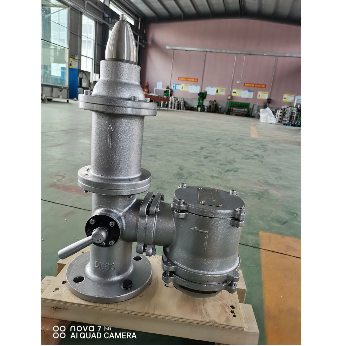
A kind of fire-fighting temperature reduction valve in order to oil tank, gas tank belongs to cooling, fire-fighting automatic control equipment field.
Existing large-scale oil storage tank, gas holder are increasingly high when ambient temperature, and for example when summer, the hull-skin temperature of oil tank, gas tank is up to six, 70 degree, even higher, causes great danger to safety in production.Oil, gas stand under the situation that this high temperature takes place, and can only artificially give oil tank, gas tank cooling with high pressure water.The open defect of this method is; Operator are difficult to the temperature rise situation of oil tank, gas tank, the situation in temperature field are grasped, and therefore also are difficult to implement cooling more accurately, cause or lower the temperature untimely having serious consequences; Blindly water, cause the waste of great water quality source.
Technological scheme of the present invention realizes like this: the present invention is made up of valve body and temperature controlling head.One columnar water outlet is arranged in the valve body, and the upper end of water outlet is equipped with the diaphragm type piston, and the relief hole on the piston cooperates with the piston column of spool bottom, has a small through hole to be communicated with the water intake of valve body on the piston; Piston column passes through fill-in pad, the magnetic post is pressed in forms spool in the valve core housing; The upper end of valve body links together through bolt and valve gap, and the center hole in the valve gap is equipped with valve core housing, and links together through welding and valve core housing; Spool is inserted in the valve core housing, and can in valve core housing, move up and down; The outside of valve core housing is with cushion pad, and the top of cushion pad is with the magnet ring cover, and the magnet ring cover is installed in magnetic ring component in the magnet ring cover through screw thread by upper and lower magnet ring lid, and the magnet ring cover can slide up and down outside valve core housing; The middle and upper part of magnet ring cover is equipped with reset spring, and the top of reset spring withstands on the internal upper part that connects cover, and the bottom that connects cover is connected with valve gap through screw thread; The upper magnetic ring lid passes and connects cover top, passes memory alloy again, is connected with fixing bolt, and fixing bolt is " T " shape structure, and last end-stopping plate withstands the upper end portion of memory alloy; The top cylindrical that connects cover is connected with the valve mounting cup through screw thread; The mounting plate that is connected with oil tank, gas tank surface is arranged at the top of valve mounting cup; Bolt hole is arranged on the mounting plate,, can valve be fixed on the surface of oil tank, gas tank through bolt; Circular heat transfer hole is arranged in the middle of the mounting plate, and the temperature on oil tank, gas tank surface can pass to this device through it; Described magnet ring, magnetic column assembly are formed by connecting the magnet same polarity more than two, have the magnetic gap sheet to separate between the magnet.
The invention has the beneficial effects as follows, but filled up the oil tank that does not have the self-powering type automatic on-off at present, the blank of gas tank cooling fire valve; Adopt the diaphragm-type servo unit structure, can improve water flow; Temperature controlling head and valve body can split, and realize the exchange of temperature control head.
Among the figure, 1 valve body, 2 pistons, 3 spools,, 4 soldering points; 5 magnetic posts, 6 magnet rings, 7 connect cover, 8 memory alloys, 9 fixing bolts, 10 heat transfer holes; 11 valve mounting cups, 12 reset springs, 13 upper magnetic rings lid, ring cowling under 14 magnetic, 15 cushion pads; 16 valve gaps, 17 valve core housings, 18 fill-in pads, 19 piston columns, water (flow) direction is seen arrow among the figure.
Accompanying drawing is the principle assumption diagram of present embodiment.The present invention is made up of valve body (1) and temperature controlling head.One columnar water outlet is arranged in the valve body (1), and the upper end of water outlet is equipped with piston (2), and the relief hole on the piston (2) cooperates with the piston column (19) of spool (3) bottom, and piston (2) is gone up and had a small through hole to be communicated with the water intake of valve body (1); Piston column (19) is pressed in composition spool (3) in the valve core housing (16) through fill-in pad (17) with magnetic post (5); The upper end of valve body (1) links together through bolt and valve gap (16), and the center hole in the valve gap (16) is equipped with valve core housing (17), and links together through welding (seeing soldering point (4)) and valve core housing (17); Spool (3) is inserted in the valve core housing (17), and can in valve core housing, move up and down; The outside of valve core housing (17) is with cushion pad (15); The top of cushion pad (15) is with the magnet ring cover; The magnet ring cover is installed in magnet ring (6) assembly in the magnet ring cover through screw thread by upper and lower magnet ring lid (13), (14), and the magnet ring cover can slide up and down outside valve core housing (17), and the middle and upper part of magnet ring cover is equipped with reset spring (12); The top of reset spring (12) withstands on the internal upper part that connects cover (7), and the bottom that connects cover (7) is connected with valve gap through screw thread; Upper magnetic ring lid (13) passes and connects cover (7) top, passes memory alloy (8) again, is connected with fixing bolt (9), and fixing bolt (9) is " T " shape structure, and last end-stopping plate withstands the upper end portion of memory alloy (8); The top cylindrical that connects cover (7) is connected with valve mounting cup (11) through screw thread; The mounting plate that is connected with oil tank, gas tank surface is arranged at the top of valve mounting cup (11); Bolt hole is arranged on the mounting plate,, can valve be fixed on the surface of oil tank, gas tank through bolt; Circular heat transfer hole (10) is arranged in the middle of the mounting plate, and the temperature on oil tank, gas tank surface can pass to apparatus of the present invention through it; Magnet ring (6), magnetic post (5) assembly are formed by connecting the magnet same polarity more than two, have the magnetic gap sheet to separate between the magnet.
Principle of the present invention is like this work, be installed on the surface of oil tank, gas tank through bolt when valve after (generally being mounted in abhiseca portion), the water intake with valve is connected with water pipeline again, water outlet can connect various mouth sprays or pipeline according to actual conditions; Memory alloy in valve (8) detects the oil tank surface temperature through heat transfer hole (10) and raises; And when surpassing the setting temperature deformation values of memory alloy (8); Memory alloy (8) deformation of expanding immediately, the mechanical thrust of generation promote fixing bolt (9) and move up, and fixing bolt (9) spur the upper magnetic ring that is attached thereto again and covers (13) and move up; Upper magnetic ring lid (13) promptly drives magnet ring (6), magnet ring lid (14) moves up down, compresses reset spring (12) simultaneously; When magnet ring (6) upwards slides outside valve core housing (17), through the magnetic post (5) in the magnetic strap movable valve plug cover (17), promptly drive spool and move up, when spool moves up; Force the piston column (19) of spool underpart, leave the relief hole of shutoff on piston (2), piston column (19) leaves the moment of piston (2) relief hole; The hydraulic pressure of piston (2) top is released, and the hydraulic pressure of the water intake on the valve body (1) backs down piston (2), also is valve open; Cooling water sprays through spraying head through water outlet again.When the surface temperature of oil tank or gas tank drops to the deformation temperature of memory alloy (8) when following gradually; Memory alloy (8) rapidly recovers to be retracted to original remember condition, under the effect of the elastic restoring force of reset spring (12), forces magnetic ring component to move down immediately; The magnetic post (5), the piston column (19) that drive in the spool move down; Piston column (19) blocks the relief hole on the piston (2) again, and under the effect of import hydraulic pressure, valve is closed rapidly.
1. an oil tank, gas tank fire control cooling valve are made up of valve body, temperature controlling head, it is characterized in that having in the valve body a columnar water outlet, and the upper end of water outlet is equipped with the diaphragm type piston; Relief hole on the piston cooperates with the piston column of spool bottom, has a small through hole to be communicated with the water intake of valve body on the piston; Piston column is pressed in the magnetic post through fill-in pad forms spool in the valve core housing; The valve body upper end is connected with valve gap through bolt, and the center hole in the valve gap links together through welding and valve core housing; Spool is inserted in the valve core housing, can in valve core housing, move up and down; The outside of valve core housing is with the magnet ring cover; The magnet ring cover is installed in magnetic ring component in the magnet ring cover through screw thread by upper and lower magnet ring lid; The magnet ring cover can slide up and down outside valve core housing; The middle and upper part of magnet ring cover is equipped with reset spring, and the top of reset spring withstands on the internal upper part that connects cover, and the bottom that connects cover is connected with valve gap through screw thread; The upper magnetic ring lid passes and connects cover top, passes memory alloy again, is connected with fixing bolt, and fixing bolt is " T " shape structure, and last end-stopping plate withstands the upper end portion of memory alloy.
2. a kind of oil tank according to claim 1, gas tank fire control cooling valve; It is characterized in that the top cylindrical that connects cover is connected with the valve mounting cup through screw thread, the mounting plate that is connected with oil tank, gas tank surface is arranged at the top of valve mounting cup, and bolt hole is arranged on the mounting plate; Pass through bolt; Can valve be fixed on the surface of oil tank, gas tank, circular heat transfer hole is arranged in the middle of the mounting plate, the temperature on oil tank, gas tank surface can pass to described oil tank, gas tank fire control cooling valve through said heat transfer hole.
When the valve is closed and the middle cavity is emptied through the discharge valve, the upstream and downstream seats will independently block. Another function of the discharge device is that the valve seat can be checked if there is a leakage during the test. In addition, the deposits inside the body can be washed through the discharge device.the discharge device is designed to reduce damage to the seat by impurities in the medium.
The trunnion pipeline ball valve adopts the trunnion ball structure and floating valve seat, so as to achieve lower torque under operating pressure. It uses self- lubricating PTFE and metal sliding bearing to reduce the friction coefficient to the lowest in conjunction with the high intensity and high fineness stem
The ball valves with the diameter more than or equal to 6"(DN150) are all designed with sealant injection device on stem and seat. When the seat ring or stem O ring is damaged due to accident, the corresponding sealant can be injected by the sealant injection device to avoid medium leakage on seat ring and stem. If necessary,the auxiliary sealing system can be used for washing and lubricating the seat to maintain its cleanliness.
In case of fire during the use of valve, the seat ring, stem O ring and middle flange O ring made of PTFE,rubber of other non-metal materials will be decomposed or damaged under high temperature.Under pressure of the medium, the ball valve will push the seat retainer rapidly towards the ball to make the metal seal ring contact the ball and form the auxiliary metal to metal sealing structure,which can effectively control valve leakage.The fireproof structure design of trunnion pipeline ball valve conforms to requirements in API 607,API 6FA,BS 6755 and other standards.
(Automatic Pressure Relief in Middle Cavity of Valve) Generally,the single sealing structure is used.That is,there is only the upstream sealing. As the independent spring loaded upstream and downstream sealing seats are used, the over-pressure inside valve cavity can overcome the pre- tightening effect of the spring,so as to make the seat released from the ball and realize automatic pressure relief towards the downstream part.The upstream side: When the seat moves axially along the valve,the pressure “P” exerted on the upstream part (inlet) produces a reverse force on A1, As A2 is higher than A1, A2-A1=B1,the force on B1 will push the seat to the ball and realize tight sealing of the upstream part
The downstream side: Once the pressure “Pb” inside the valve Cavity increases, the force exerted on A3 is higher than that on A4. As A3-A4=B2, the pressure differential on B2 will overcome the spring force to make the seat released from the ball and realize pressure relief of valve cavity to the downstream part afterwards,the seat and ball will be sealed again under the spring action.
The trunnion pipeline ball valve can be designed with the double Sealing structure before and after the ball for some special service conditions and user requirements. It has double piston effect. Under normal condition,the valve generally adopts primary sealing.When the primary seat sealing us damaged and causes leakage,the secondary seat can play the function of sealing and enhance the sealing reliability. the seat adopts the combined structure.The primary seal is metal to metal seal.The secondary seal is fluorine rubber O ring that can ensure the ball valve can reach the bubble level sealing. When the pressure differential is very low,the sealing seat will press the ball through the spring action to realize primary sealing. When the pressure differential rises,the sealing force of seat and body will increase accordingly so as to tightly seal the seat and ball and ensure good sealing performance.
When the pressure differential is lower or there is no pressure differential, the floating seat will move axially along the valve under the spring action and pish the seat towards the ball to keep tight sealing. When the of valve seat is higher than the force exerted on the area A1,A2- A1=B1.Therefore,the force in B1 will push the seat towards the Ball and realize tight sealing of the upstream part.
When the pressure differential is lower or there is no pressure differential,the floating seat will move axially along the valve under the spring action and push the seat towards the ball to keep tight sealing. When the valve cavity pressure P increases,the force exerted on the area A4 of valve seat in higher than the force exerted on the area A3,A4- A3=B1.Therefore,the force on B1 will push the seat towards the ball and realize tight sealing of the upstream part.
As the ball valve is designed with the advanced primary and secondary sealing that has double piston effect,and the middle cavity cannot realize automatic pressure relief, the safety relief valve must be installed on the body in order to prevent the danger of over-pressure damage inside the valve cavity that may occur due to thermal expansion of medium.The connection of the safety relief valve is generally NPT 1/2. Another point to be noted is that the medium of the safety relief valve is directly discharged into the atmosphere. In case direct discharging into the atmosphere is not allowed, we suggest that the ball valve with a special structure of automatic pressure relief towards upper stream should be used.Refer to the following for details. Please indicate it in the order if you do not need the safety relief valve or if you would like to use the ball valve with the special structure of automatic pressure relief towards upper stream.
As the ball valve is designed with the advanced primary and secondary sealing that has double piston effect,and the middle cavity cannot realize automatic pressure relief, he ball valve ith the special structure is recommended to meet the requirements of automatic pressure relief and ensure no pollution to the environment.In the structure,the upper stream adopts primary sealing and the lower stream adopts primary and secondary sealing When the ball valve is closed,the pressure in the valve cavity can realize automatic pressure relief to the upper stream,so as to avoid the danger caused by cavity pressure.When the primary seat is damaged and leaks,the secondary seat can also play the function of sealing.But special attention shall be paid to the flow direction of the ball valve.During the installation.Note the upstream and downstream directions.Refer to the following drawings for sealing principle of the valve with the special structure
The stem adopts the blow-out proof structure.The stem is designed with the footstep at its bottom so that with the positioning of upper end cover and screw,the stem will not be blown out by the medium even in case of abnormal pressure rise in the valve cavity.
As for the embedded valve,the extension stem can be supplied if ground operation is required.The extension stem is composed of stem, sealant injection valve,and drainage valve that can be extended to the top for the convenience of operation. Users should indicate the extension stem requirements and length when placing orders. For ball valve driven through electric,pneumatic and pneumatic – hydraulic actuators,the extension stem length should be from the center of pipeline to top flange.

Brass safety Valve Accessories are one of the most important safety accessories for air conditioners, heat pumps, boilers, pressure vessels, pipes and other pressure equipment, which is used to control the pressure does not exceed the specified value and plays an important role in protecting personal safety and equipment operation.
Our Rietti Oil Tank Shut off Valve China Pneumatic Solenoid Valve Manufacturer Wholesale OEM Custom PPR Stop Valves Straight Through Type Safety Shut off Valve have stable and reliable quality, stable quality and perfect after-sales service system, which make us deeply loved by consumers. We will continue to serve our customers wholeheartedly with super first-class product quality and service quality. After years of development, the company has now established a complete pre-sale, in-sale and after-sales service system, all for the satisfaction of customers.
Because of different of drive source, SSV can dividedinto Hydraulic safety valve and pneumatic valve ; With thermal and high voltage explosion-proof device ; Actuators and prepare two parts of the valve, standard interface, easy replacement and maintenance .
This valve is used for power plant boilers, pressure containers, pressure and temperature reducing device and other facilities. It serves to prevent the pressure exceeding the highest allowable pres-sure value and ensure the safety of the device when working.
(1)The pressure of the disc is balanced through the lever and heavy hammer and the valve is ensured seal by moving the for ton of heavy hammer and changing the weight of heavy hammer to reach the required set pressure.
(3)At the top of valve is equipped an electromagnet to open and another to close the valve. The actions of the mechanism and the electric appliance are separate and will not affect each other.
(2)Impulse safety valve shall be installed vertically and the lever shall be kept level. The clearance from the lever to both sides of guide fork shall be even.
(4)A long distance between the leading pipe of the impulse safety valve and the inlet pipe of the main safety valve shall be kept. And the distance between the electric contact pressure meter and the inlet pipe of the main safety valve shall be no less than 5 times of the diameter of the inlet pipe, for feat that the validity of the mater and the impulse safety valve may be affected by the steam releasing process of the main safety valve.
This valve is used for power plant boilers, pressure containers, pressure and temperature reducing device and other facilities. It serves to present the pressure exceeding the highest allowable pres-sure value and ensure the safety of the device when working.
1,When the medium pressure rises to the set pressure, the in-pulse safety valve opens, and the medium in the impulse pipe enters into the piston chamber of the main safety valve from impulse pipe, forcing the piston to descend, and then the valve automatically open-s; when the impulse safety valve closes, the disc will slash automatically close.
2,The main safety valve shall be fastened upon the gallows, which sustains the back-seat force produced in the steam discharging process of the main safety valve.
3,The exhaust pipe shall contain a special gallows to prevent the force of its weight directly applying on the main safety valve. The connecting Lange At the lowest point of the exhaust pipe, water drainage shall be taken into consideration to avoid producing water hammer while discharging set between the main safety valve and exhaust pipe shall eliminate any extra stress.

FK-5-1-12/Novec 1230 is an odorless, colorless, liquefied compressed gas. It is stored as a liquid and dispensed into the hazard as a colorless, electrically non-conductive vapor that is clear and does not obscure vision. It leaves no residue and has acceptable toxicity for use in occupied spaces at design concentration. FK-5-1-12/Novec 1230 extinguishes a fire by a combination of chemical and physical mechanisms.
FK-5-1-12/Novec 1230 provides excellent fire protection in a wide range of applications from sensitive electrical equipment to industrial applications using flammable liquids. FK-5-1-12/Novec 1230 agent is used in total flooding fire suppression systems.
When the control mode selection key on the automatic fire alarm and fire extinguishing controller is set to the "auto"position, the fire extinguishing system is under automatic control. When a fire occurs in the protection area, the temperature and smoke detectors will send out a fire signal through the automatic fire alarm and extinguishing control After the logic analysis of the device, it sends out a combined sound and light alarm signal, and sends out a linkage command at the same time to close the linkage device. After a delay, a fire extinguishing command is issued, the starting valve is opened to release the starting gas, and the starting gas is opened through the control gas pipeline valves and container valves release the fire extinguishing agent and implement fire extinguishing.
We also have Cabinet Type FK-5-1-12 / HFC-227ea total Flooding Fire System, FK-5-1-12/ HFC-227ea fire extinguishing system Cabinet Type FK-5-1-12/ HFC-227ea Fire Extinguisher

Certification: TS licensing A1, A2, B1, B2, API-6D, CE, ISO9001, ISO14001, OHSAS18001, TUV issued by the API 6FA gate valve, API607 ball valve fireproof test
Neway Valve is one of the leading manufacturers of butterfly valves in China. It has a world-class valve plant that covers an extensive valve program to meet the needs of clients.
Neway butterfly valves are available in a number of series including T Series for concentric butterfly valves, TB Series for double offset butterfly valves, and TC Series for triple offset butterfly valves. These valves are used largely in chemical, nuclear, offshore, power, oil and gas, mining, and air separation industry.
Chaoda Group Wenzhou E-business Co., Ltd is an entirely owned branch of the Chaoda Valves Group Co., Ltd to market and sell valves, forging, casting, flanging, gas meter, etc. The company has earned special titles such as “Zhejiang Famous Product,” “Zhejiang Famous Brand,” and “Zhejiang Exporting Famous Brand.”
Chaoda houses a variety of cryogenic valves that are suitable for many different industries. They feature cryogenic globe, butterfly, check, trunnion ball, floating ball, check, gate, and other valves.
Chaoda forged steel cryogenic lift check valve is immersed in liquid nitrogen (-196 degree C) for 2 to 6 hours, then returned to normal temperature during production. This cycle is repeated twice to ensure the valve’s cryogenic abilities are top-notch. The valve can be made of carbon steel, stainless steel, alloy steel, and duplex stainless steel. It can be operated manually, by gear, electrically, or pneumatically. The valve can be used with oil, chemicals, natural gas, petrochemicals, coal chemicals, and more.
Beijing Valve General Factory Co., Ltd, or BVMC,was founded in 1953. With more than six decades of experience in the industry, the company has earned the position of vice chairman of National Valve Industry Association.
Beijing Valve General Factory has more than 60 years of experience in valve design and manufacturing. The company is actively involved in many national projects and also exports valves to more than 70 countries and regions around the world.
Their cryogenic ball valve can be used in temperatures ranging from -196 to 121 degrees C. The valve can be used with LNG and liquid nitrogen and is fire-safe and anti-static. The valve stem is extended and has extra packing ensuring any anti-flow. You can operate the valve with a handwheel, worm wheel, electric actuator or pneumatic actuator.

Only approved containers and portable tanks shall be used for storage and handling of flammable liquids. Approved safety cans or Department of Transportation approved containers shall be used for the handling and use of flammable liquids in quantities of 5 gallons or less, except that this shall not apply to those flammable liquid materials which are highly viscid (extremely hard to pour), which may be used and handled in original shipping containers. For quantities of one gallon or less, the original container may be used, for storage, use and handling of flammable liquids.
Acceptable wooden storage cabinets shall be constructed in the following manner, or equivalent: The bottom, sides, and top shall be constructed of an exterior grade of plywood at least 1 inch in thickness, which shall not break down or delaminate under standard fire test conditions. All joints shall be rabbeted and shall be fastened in two directions with flathead wood screws. When more than one door is used, there shall be a rabbeted overlap of not less than 1 inch. Steel hinges shall be mounted in such a manner as to not lose their holding capacity due to loosening or burning out of the screws when subjected to fire. Such cabinets shall be painted inside and out with fire retardant paint.
Inside storage rooms shall be constructed to meet the required fire-resistive rating for their use. Such construction shall comply with the test specifications set forth in Standard Methods of Fire Test of Building Construction and Material, NFPA 251-1969.
Where an automatic extinguishing system is provided, the system shall be designed and installed in an approved manner. Openings to other rooms or buildings shall be provided with noncombustible liquid-tight raised sills or ramps at least 4 inches in height, or the floor in the storage area shall be at least 4 inches below the surrounding floor. Openings shall be provided with approved self-closing fire doors. The room shall be liquid-tight where the walls join the floor. A permissible alternate to the sill or ramp is an open-grated trench, inside of the room, which drains to a safe location. Where other portions of the building or other buildings are exposed, windows shall be protected as set forth in the Standard for Fire Doors and Windows, NFPA No. 80-1970, for Class E or F openings. Wood of at least 1-inch nominal thickness may be used for shelving, racks, dunnage, scuffboards, floor overlay, and similar installations.
The storage area shall be graded in a manner to divert possible spills away from buildings or other exposures, or shall be surrounded by a curb or earth dike at least 12 inches high. When curbs or dikes are used, provisions shall be made for draining off accumulations of ground or rain water, or spills of flammable liquids. Drains shall terminate at a safe location and shall be accessible to operation under fire conditions.
Portable tanks shall not be nearer than 20 feet from any building. Two or more portable tanks, grouped together, having a combined capacity in excess of 2,200 gallons, shall be separated by a 5-foot-clear area. Individual portable tanks exceeding 1,100 gallons shall be separated by a 5-foot-clear area.
Portable tanks, not exceeding 660 gallons, shall be provided with emergency venting and other devices, as required by chapters III and IV of NFPA 30-1969, The Flammable and Combustible Liquids Code.
Portable tanks, in excess of 660 gallons, shall have emergency venting and other devices, as required by chapters II and III of The Flammable and Combustible Liquids Code, NFPA 30-1969.
At least one portable fire extinguisher, having a rating of not less than 20-B units, shall be located outside of, but not more than 10 feet from, the door opening into any room used for storage of more than 60 gallons of flammable liquids.
At least one portable fire extinguisher having a rating of not less than 20-B units shall be located not less than 25 feet, nor more than 75 feet, from any flammable liquid storage area located outside.
At least one portable fire extinguisher having a rating of not less than 20-B:C units shall be provided on all tank trucks or other vehicles used for transporting and/or dispensing flammable liquids.
Areas in which flammable liquids are transferred at one time, in quantities greater than 5 gallons from one tank or container to another tank or container, shall be separated from other operations by 25-feet distance or by construction having a fire resistance of at least 1 hour. Drainage or other means shall be provided to control spills. Adequate natural or mechanical ventilation shall be provided to maintain the concentration of flammable vapor at or below 10 percent of the lower flammable limit.
Flammable liquids shall be drawn from or transferred into vessels, containers, or tanks within a building or outside only through a closed piping system, from safety cans, by means of a device drawing through the top, or from a container, or portable tanks, by gravity or pump, through an approved self-closing valve. Transferring by means of air pressure on the container or portable tanks is prohibited.
The tank trucks shall comply with the requirements covered in the Standard for Tank Vehicles for Flammable and Combustible Liquids, NFPA No. 385-1966.
Each service or fueling area shall be provided with at least one fire extinguisher having a rating of not less than 20-B:C located so that an extinguisher will be within 75 feet of each pump, dispenser, underground fill pipe opening, and lubrication or service area.
Tanks may be built of materials other than steel for installation underground or if required by the properties of the liquid stored. Tanks located above ground or inside buildings shall be of noncombustible construction.
Tanks built of materials other than steel shall be designed to specifications embodying principles recognized as good engineering design for the material used.
Unlined concrete tanks may be used for storing flammable liquids having a gravity of 40 deg. API or heavier. Concrete tanks with special lining may be used for other services provided the design is in accordance with sound engineering practice.
Special engineering consideration shall be required if the specific gravity of the liquid to be stored exceeds that of water or if the tanks are designed to contain flammable liquids at a liquid temperature below 0 deg. F.
Metal tanks shall be welded, riveted, and caulked, brazed, or bolted, or constructed by use of a combination of these methods. Filler metal used in brazing shall be nonferrous metal or an alloy having a melting point above 1000 deg. F. and below that of the metal joined.
Underwriters" Laboratories, Inc., Subjects No. 142, Standard for Steel Aboveground Tanks for Flammable and Combustible Liquids, 1968; No. 58, Standard for Steel Underground Tanks for Flammable and Combustible Liquids, Fifth Edition, December 1961; or No. 80, Standard for Steel Inside tanks for Oil-Burner Fuel, September 1963.
American Petroleum Institute Standards No. 12A, Specification for Oil Storage Tanks with Riveted Shells, Seventh Edition, September 1951, or No. 650, Welded Steel Tanks for Oil Storage, Third Edition, 1966.
American Petroleum Institute Standards No. 12B, Specification for Bolted Production Tanks, Eleventh Edition, May 1958, and Supplement 1, March 1962; No. 12D, Specification for Large Welded Production Tanks, Seventh Edition, August 1957; or No. 12F, Specification for Small Welded Production Tanks, Fifth Edition, March 1961. Tanks built in accordance with these standards shall be used only as production tanks for storage of crude petroleum in oil-producing areas.
American Petroleum Institute Standard No. 620. Recommended Rules for the Design and Construction of Large, Welded, Low-Pressure Storage Tanks, Third Edition, 1966.
Atmospheric tanks built according to Underwriters" Laboratories, Inc., requirements in paragraph (i)(1)(iii)(A) of this section and shall be limited to 2.5 p.s.i.g. under emergency venting conditions.
Pressure vessels shall be built in accordance with the Code for Unfired Pressure Vessels, Section VIII of the ASME Boiler and Pressure Vessel Code 1968.
"Provisions for internal corrosion." When tanks are not designed in accordance with the American Petroleum Institute, American Society of Mechanical Engineers, or the Underwriters" Laboratories, Inc."s, standards, or if corrosion is anticipated beyond that provided for in the design formulas used, additional metal thickness or suitable protective coatings or linings shall be provided to compensate for the corrosion loss expected during the design life of the tank.
Except as provided in paragraph (i)(2)(ii)(C) of this section, the distance between any two adjacent tanks shall not be less than one-sixth the sum of their diameters. When the diameter of one tank is less than one-half the diameter of the adjacent tank, the distance between the two tanks shall not be less than one-half the diameter of the smaller tank.
Where crude petroleum in conjunction with production facilities are located in noncongested areas and have capacities not exceeding 126,000 gallons (3,000 barrels), the distance between such tanks shall not be less than 3 feet (0.912 m).
When tanks are compacted in three or more rows or in an irregular pattern, greater spacing or other means shall be provided so that inside tanks are accessible for firefighting purposes.
The minimum separation between a liquefied petroleum gas container and a flammable liquid storage tank shall be 20 feet (6.08 m), except in the case of flammable liquid tanks operating at pressures exceeding 2.5 p.s.i.g. or equipped with emergency venting which will permit pressures to exceed 2.5 p.s.i.g. in which case the provisions of paragraphs (i)(2)(ii)(A) and (B) of this section shall apply. Suitable means shall be taken to prevent the accumulation of flammable liquids under adjacent liquefied petroleum gas containers such as by diversion curbs or grading. When flammable liquid storage tanks are within a diked area, the liquefied petroleum gas containers shall be outside the diked area and at least 10 feet (3.04 m) away from the centerline of the wall of the diked area. The foregoing provisions shall not apply when liquefied petroleum gas containers of 125 gallons (473.125 L) or less capacity are installed adjacent to fuel oil supply tanks of 550 gallons (2,081.75 L) or less capacity.
Atmospheric storage tanks shall be adequately vented to prevent the development of vacuum or pressure sufficient to distort the roof of a cone roof tank or exceeding the design pressure in the case of other atmospheric tanks, as a result of filling or emptying, and atmospheric temperature changes.
Low-pressure tanks and pressure vessels shall be adequately vented to prevent development of pressure or vacuum, as a result of filling or emptying and atmospheric temperature changes, from exceeding the design pressure of the tank or vessel. Protection shall also be provided to prevent overpressure from any pump discharging into the tank or vessel when the pump discharge pressure can exceed the design pressure of the tank or vessel.
If any tank or pressure vessel has more than one fill or withdrawal connection and simultaneous filling or withdrawal can be made, the vent size shall be based on the maximum anticipated simultaneous flow.
Unless the vent is designed to limit the internal pressure 2.5 p.s.i. or less, the outlet of vents and vent drains shall be arranged to discharge in such a manner as to prevent localized overheating of any part of the tank in the event vapors from such vents are ignited.
Tanks and pressure vessels storing Category 1 flammable liquids shall be equipped with venting devices that shall be normally closed except when venting to pressure or vacuum conditions. Tanks and pressure vessels storing Category 2 flammable liquids, or Category 3 flammable liquids with a flashpoint below 100 ºF (37.8 ºC), shall be equipped with venting devices that shall be normally closed except when venting under pressure or vacuum conditions, or with approved flame arresters.
Exemption: Tanks of 3,000 bbls (barrels) (84 m(3)) capacity or less containing crude petroleum in crude-producing areas; and, outside aboveground atmospheric tanks under 1,000 gallons (3,785 L) capacity containing other than Category 1 flammable liquids may have open vents. (See paragraph (i)(2)(vi)(B) of this section.)
Flame arresters or venting devices required in paragraph (i)(2)(iv)(F) of this section may be omitted for Category 2 flammable liquids or Category 3 flammable liquids with a flashpoint below 100 ºF (37.8 ºC) where conditions are such that their use may, in case of obstruction, result in tank damage.
In a vertical tank the construction referred to in paragraph (i)(2)(v)(A) of this section may take the form of a floating roof, lifter roof, a weak room-to-shell seam, or other approved pressure relieving construction. The weak roof-to-shell seam shall be constructed to fail preferential to any other seam.
Where entire dependence for emergency relief is placed upon pressure relieving devices, the total venting capacity of both normal and emergency vents shall be enough to prevent rupture of the shell or bottom of the tank if vertical, or of the shell or heads if horizontal. If unstable liquids are stored, the effects of heat or gas resulting from polymerization, decomposition, condensation, or self-reactivity shall be taken into account. The total capacity of both normal and emergency venting devices shall be not less than that derived from Table F-10 except as provided in paragraph (i)(2)(v)(E) or (F) of this section. Such device may be a self-closing manhole cover, or one using long bolts that permit the cover to lift under internal pressure, or an additional or larger relief valve or valves. The wetted area of the tank shall be calculated on the basis of 55 percent of the total exposed area of a sphere or spheroid, 75 percent of the total exposed area of a horizontal tank and the first 30 feet (9.12 m) above grade of the exposed shell are of a vertical tank.
For tanks and storage vessels designed for pressure over 1 p.s.i.g., the total rate of venting shall be determined in accordance with Table F-10, except that when the exposed wetted area of the surface is greater than 2,800 square feet (257.6 m(2)), the total rate of venting shall be calculated by the following formula:
The required airflow rate of paragraph (i)(2)(v)(C) or (E) of this section may be multiplied by the appropriate factor listed in the following schedule when protection is provided as indicated. Only one factor may be used for any one tank.
The outlet of all vents and vent drains on tanks equipped with emergency venting to permit pressures exceeding 2.5 p.s.i.g. shall be arranged to discharge in such a way as to prevent localized overheating of any part of the tank, in the event vapors from such vents are ignited.
Each commercial tank venting device shall have stamped on it the opening pressure, the pressure at which the valve reaches the full open position, and the flow capacity at the latter pressure, expressed in cubic feet (meters) per hour of air at 60 deg. F. (15.55 deg C) and at a pressure of 14.7 p.s.i.a.
The flow capacity of tank venting devices 12 inches (30.48 cm) and smaller in nominal pipe size shall be determined by actual test of each type and size of vent. These flow tests may be conducted by the manufacturer if certified by a qualified impartial observer, or may be conducted by an outside agency. The flow capacity of tank venting devices larger than 12 inches (30.48 cm) nominal pipe size, including manhole covers with long bolts or equivalent, may be calculated provided that the opening pressure is actually measured, the rating pressure and corresponding free orifice area are stated, the word "calculated" appears on the nameplate, and the computation is based on a flow coefficient of 0.5 applied to the rated orifice area.
Where vent pipe outlets for tanks storing Category 1 or 2 flammable liquids, or Category 3 flammable liquids with a flashpoint below 100 ºF (37.8 ºC), are adjacent to buildings or public ways, they shall be located so that the vapors are released at a safe point outside of buildings and not less than 12 feet (3.658 m) above the adjacent ground level. In order to aid their dispersion, vapors shall be discharged upward or horizontally away from closely adjacent walls. Vent outlets shall be located so that flammable vapors will not be trapped by eaves or other obstructions and shall be at least 5 feet (1.52 m) from building openings.
When tank vent piping is manifolded, pipe sizes shall be such as to discharge, within the pressure limitations of the system, the vapors they may be required to handle when manifolded tanks are subject to the same fire exposure.
"Drainage and diked areas." The area surrounding a tank or a group of tanks shall be provided with drainage as in paragraph (i)(2)(vii)(B) of this section, or shall be diked as provided in (i)(2)(vii)(C) of this section, to prevent accidental discharge of liquid from endangering adjoining property or reaching waterways.
The drainage system shall terminate in vacant land or other area or in an impounding basin having a capacity not smaller than that of the largest tank served. This termination area and the route of the drainage system shall be so located that, if the flammable liquids in the drainage system are ignited, the fire will not seriously expose tanks or adjoining property.
"Diked areas." Where protection of adjoining property or waterways is accomplished by retaining the liquid around the tank by means of a dike, the volume of the diked area shall comply with the following requirements:
Except as provided in paragraph (1)(2)(vii)(C)(2) of this section, the volumetric capacity of the diked area shall not be less than the greatest amount of liquid that can be released from the largest tank within the diked area, assuming a full tank. The capacity of the diked area enclosing more than one tank shall be calculated by deducting the volume of the tanks other than the largest tank below the height of the dike.
For a tank or group of tanks with fixed roofs containing crude petroleum with boilover characteristics, the volumetric capacity of the diked area shall be not less than the capacity of the largest tank served by the enclosure, assuming a full tank. The capacity of the diked enclosure shall be calculated by deducting the volume below the height of the dike of all tanks within the enclosure.
For Category 2 flammable liquids or Category 3 flammable liquids with a flashpoint below 100 ºF (37.8 ºC), other than crude oils, gasolines, and asphalts, the fill pipe shall be so designed and installed as to minimize the possibility of generating static electricity. A fill pipe entering the top of a tank shall terminate within 6 inches (15.24 cm) of the bottom of the tank and shall be installed to avoid excessive vibration.
Location. Evacuation for underground storage tanks shall be made with due care to avoid undermining of foundations of existing structures. Underground tanks or tanks under buildings shall be so located with respect to existing building foundations and supports that the loads carried by the latter cannot be transmitted to the tank. The distance from any part of a tank storing Category 1 or 2 flammable liquids, or Category 3 flammable liquids with a flashpoint below 100 ºF (37.8 ºC), to the nearest wall of any basement or pit shall be not less than 1 foot (0.304 m), and to any property line that may be built upon, not less than 3 feet (0.912 m). The distance from any part of a tank storing Category 3 flammable liquids with a flashpoint at or above 100 ºF (37.8 ºC) or Category 4 flammable liquids to the nearest wall of any basement, pit or property line shall be not less than 1 foot (0.304 m).
"Depth and cover." Underground tanks shall be set on firm foundations and surrounded with at least 6 inches (15.24 cm) of noncorrosive, inert materials such as clean sand, earth, or gravel well tamped in place. The tank shall be placed in the hole with care since dropping or rolling the tank into the hole can break a weld, puncture or damage the tank, or scrape off the protective coating of coated tanks. Tanks shall be covered with a minimum of 2 feet(0.608 m) of earth, or shall be covered with not less than 1 foot (0.304 m) of earth, on top of which shall be placed a slab of reinforced concrete not less than 4 inches (10.16 cm) thick. When underground tanks are, or are likely to be, subject to traffic, they shall be protected against damage from vehicles passing over them by at least 3 feet (0.912 m) of earth cover, or 18 inches (45.72 cm) of well-tamped earth, plus 6 inches (15.24 cm) of reinforced concrete or 8 inches (20.32 cm) of asphaltic concrete. When asphaltic or reinforced concrete paving is used as part of the protection, it shall extend at least 1 foot (0.304 m) horizontally beyond the outline of the tank in all directions.
Location and arrangement of vents for Category 1 or 2 flammable liquids, or Category 3 flammable liquids with a flashpoint below 100 ºF (37.8 ºC). Vent pipes from tanks storing Category 1 or 2 flammable liquids, or Category 3 flammable liquids with a flashpoint below 100 ºF (37.8 ºC), shall be so located that the discharge point is outside of buildings, higher than the fill pipe opening, and not less than 12 feet (3.658 m) above the adjacent ground level. Vent pipes shall discharge only upward in order to disperse vapors. Vent pipes 2 inches (5.08 cm) or less in nominal inside diameter shall not be obstructed by devices that will cause excessive back pressure. Vent pipe outlets shall be so located that flammable vapors will not enter building openings, or be trapped under eaves or other obstructions. If the vent pipe is less than 10 feet (3.04 m) in length, or greater than 2 inches (5.08 cm) in nominal inside diameter, the outlet shall be provided with a vacuum and pressure relief device or there shall be an approved flame arrester located in the vent line at the outlet or within the approved distance from the outlet.
Size of vents. Each tank shall be vented through piping adequate in size to prevent blow-back of vapor or liquid at the fill opening while the tank is being filled. Vent pipes shall be not less than 1 1/4 inch (3.175 cm) nominal inside diameter.
Location and arrangement of vents for Category 3 flammable liquids with a flashpoint at or above 100 ºF (37.8 ºC) or Category 4 flammable liquids. Vent pipes from tanks storing Category 3 flammable liquids with a flashpoint at or above 100 ºF (37.8 ºC) or Category 4 flammable liquids shall terminate outside of the building and higher than the fill pipe opening. Vent outlets shall be above normal snow level. They may be fitted with return bends, coarse screens or other devices to minimize ingress of foreign material.
Vent piping shall be constructed in accordance with paragraph (3)(iv)(C) of this section. Vent pipes shall be so laid as to drain toward the tank without sags or traps in which liquid can collect. They shall be located so that they will not be subjected to physical damage. The tank end of the vent pipe shall enter the tank through the top.
When tank vent piping is manifolded, pipe sizes shall be such as to discharge, within the pressure limitations of the system, the vapors they may be required to handle when manifolded tanks are filled simultaneously.
Openings for manual gaging, if independent of the fill pipe, shall be provided with a liquid-tight cap or cover. If inside a building, each such opening shall be protected against liquid overflow and possible vapor release by means of a spring loaded check valve or other approved device.
For Category 2 flammable liquids, or Category 3 flammable liquids with a flashpoint below 100 ºF (37.8 ºC), other than crude oils, gasolines, and asphalts, the fill pipe shall be so designed and installed as to minimize the possibility of generating static electricity by terminating within 6 inches (15.24 cm) of the bottom of the tank.
"Vents." Vents for tanks inside of buildings shall be as provided in paragraphs (i)(2)(iv), (v), (vi)(B), and (3)(iv) of this section, except that emergency venting by the use of weak roof seams on tanks shall not be permitted. Vents shall discharge vapors outside the buildings.
Each connection to a tank inside of buildings through which liquid can normally flow shall be provided with an internal or external valve located as close as practical to the shell of the tank. Such valves, when external, and their connections to the tank shall be of steel except when the chemical characteristics of the liquid stored are incompatible with steel. When materials other than steel are necessary, they shall be suitable for the pressures, structural stresses, and temperatures involved, including fire exposures.
Flammable liquid tanks located inside of buildings, except in one-story buildings designed and protected for flammable liquid storage, shall be provided with an automatic-closing heat-actuated valve on each withdrawal connection below the liquid level, except for connections used for emergency disposal, to prevent continued flow in the event of fire in the vicinity of the tank. This function may be incorporated in the valve required in paragraph (i)(4)(iv)(B) of this section, and if a separate valve, shall be located adjacent to the valve required in paragraph (i)(4)(iv)(B) of this section.
Openings for manual gaging, if independent of the fill pipe (see paragraph (i)(4)(iv)(F) of this section), shall be provided with a vaportight cap or cover. Each such opening shall be protected against liquid overflow and possible vapor release by means of a spring loaded check valve or other approved device.
For Category 2 flammable liquids, or Category 3 flammable liquids with a flashpoint below 100 ºF (37.8 ºC), other than crude oils, gasolines, and asphalts, the fill pipe shall be so designed and installed as to minimize the possibility of generating static electricity by terminating within 6 inches (15.24 cm) of the bottom of the tank.
"General." Tank supports shall be installed on firm foundations. Tank supports shall be of concrete, masonry, or protected steel. Single wood timber supports (not cribbing) laid horizontally may be used for outside aboveground tanks if not more than 12 inches (30.48 cm) high at their lowest point.
"Fire resistance." Steel supports or exposed piling shall be protected by materials having a fire resistance rating of not less than 2 hours, except that steel saddles need not be protected if less than 12 inches (30.48 cm) high at their lowest point. Water spray protection or its equivalent may be used in lieu of fire-resistive materials to protect supports.
"Foundations." Tanks shall rest on the ground or on foundations made of concrete, masonry, piling, or steel. Tank foundations shall be designed to minimize the possibility of uneven settling of the tank and to minimize corrosion in any part of the tank resting on the foundation.
"Flood areas." Where a tank is located in an area that may be subjected to flooding, the applicable precautions outlined in this subdivision shall be observed.
No aboveground vertical storage tank containing a flammable liquid shall be located so that the allowable liquid level within the tank is below the established maximum flood stage, unless the tank is provided with a guiding structure such as described in paragraphs (i)(5)(vi)(M), (N), and (O) of this section.
Independent water supply facilities shall be provided at locations where there is no ample and dependable public water supply available for loading partially empty tanks with water.
In addition to the preceding requirements, each tank so located that more than 70 percent, but less than 100 percent, of its allowable liquid storage capacity will be submerged at the established maximum flood stage, shall be safeguarded by one of the following methods: Tank shall be raised, or its height shall be increased, until its top extends above the maximum flood stage a distance equivalent to 30 percent or more of its allowable liquid storage capacity: "Provided, however," That the submerged part of the tank shall not exceed two and one-half times the diameter. Or, as an alternative to the foregoing, adequate noncombustible structural guides, designed to permit the tank to float vertically without loss of product, shall be provided.
Each horizontal tank so located that more than 70 percent of its storage capacity will be submerged at the established flood stage, shall be anchored, attached to a foundation of concrete or of steel and concrete, of sufficient weight to provide adequate load for the tank when filled with flammable liquid and submerged by flood waters to the established flood stage, or adequately secured by other means.
At locations where there is no ample and dependable water supply, or where filling of underground tanks with liquids is impracticable because of the character of their contents, their use, or for other reasons, each tank shall be safeguarded against movement when empty and submerged by high ground water or flood waters by anchoring, weighting with concrete or other approved solid loading material, or securing by other means. Each such tank shall be so constructed and installed that it will safety resist external pressures due to high ground water or flood waters.
At locations where there is an ample and dependable water supply available, underground tanks containing flammable liquids, so installed that more than 70 percent of their storage capacity will be submerged at the maximum flood stage, shall be so anchored, weighted, or secured by other means, as to prevent movement by such tanks when filled with flammable liquids, and submerged by flood waters to the established flood stage.
Pipe connections below the allowable liquid level in a tank shall be provided with valves or cocks located as closely as practicable to the tank shell. Such valves and their connections to tanks shall be of steel or other material suitable for use with the liquid being stored. Cast iron shall not be permitted.
At locations where an independent water supply is required, it shall be entirely independent of public power and water supply. Independent source of water shall be available when flood waters reach a level not less than 10 feet (3.04 m) below the bottom of the lowest tank on a property.
The self-contained power and pumping unit shall be so located or so designed that pumping into tanks may be carried on continuously throughout the rise in flood waters from a level 10 feet (3.04 m) below the lowest tank to the level of the potential flood stage.
Capacity of the pumping unit shall be such that the rate of rise of water in all tanks shall be equivalent to the established potential average rate of rise of flood waters at any stage.
Structural guides for holding floating tanks above their foundations shall be so designed that there will be no resistance to the free rise of a tank, and shall be constructed of noncombustible material.
The strength of the structure shall be adequate to resist lateral movement of a tank subject to a horizontal force in any direction equivalent to not less than 25 pounds per square foot (1.05 kg m(2)) acting on the projected vertical cross-sectional area of the tank.
Where tanks are situated on exposed points or bends in a shoreline where swift currents in flood waters will be present, the structures shall be designed to withstand a unit force of not less than 50 pounds per square foot (2.1 kg m(2)).
The filling of a tank to be protected by water loading shall be started as soon as flood waters reach a dangerous flood stage. The rate of filling shall be at least equal to the rate of rise of the floodwaters (or the established average potential rate of rise).
Where structural guides are provided for the protection of floating tanks, all rigid connections between tanks and pipelines shall be disconnected and blanked off or blinded before the floodwaters reach the bottom of the tank, unless control valves and their connections to the tank are of a type designed to prevent breakage between the valve and the tank shell.
That station operators and other employees depended upon to carry out such instructions are thoroughly informed as to the location and operation of such valves and other equipment necessary to effect these requirements.
"General." All tanks, whether shop built or field erected, shall be strength tested before they are placed in service in accordance with the applicable paragraphs of the code under which they were built. The American Society of Mechanical Engineers (ASME) code stamp, American Petroleum Institute (API) monogram, or the label of the Underwriters" Laboratories, Inc., on a tank shall be evidence of compliance with this strength test. Tanks not marked in accordance with the above codes shall be strength tested before they are placed in service in accordance with good engineering principles and reference shall be made to the sections on testing in the codes listed in paragraphs (i)(1)(iii)(A), (iv)(B), or (v)(B) of this section.
"Strength." Wh


 8613371530291