
online safety valve testing equipment free sample
The new platform of CALDER advanced valve testing systems manufactured by CLIMAX are the safest, most accurate and most versatile systems on the market, and we are pleased to announce our new line-up of valve testing equipment.
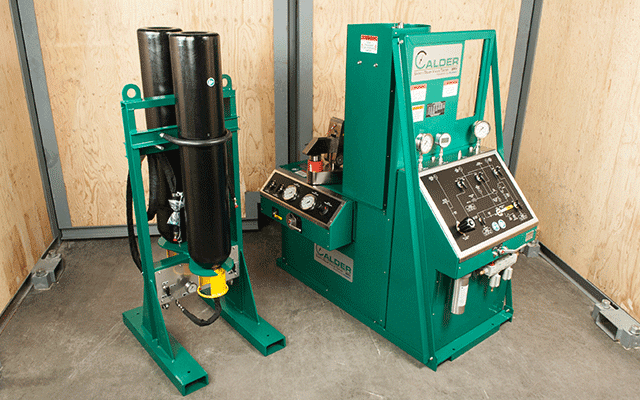
The HYDROPRO™ Console is the most versatile and user-friendly tester in the industry, capable of performing a wide variety of valve tests when paired with a CALDER hydraulic clamping system or even blind flanging. Every component in the tester is OEM-certified to the maximum pressure of the system, CE certified, and manufactured under full ISO certification – no one else in the industry can say the same! This means vastly superior quality, safety, durability and performance for you, our customer. Our testers are infinitely configurable to meet your exact needs, and our modular, common-platform design ensures that all equipment and accessories are plug-and-play compatible, so we can upgrade/expand your system in the field, anytime in the future, to meet your changing business needs. This is by far the most flexible and cost-effective way to manage your valve testing program and maximize your return on investment. HYDROPRO™ is available world-wide and backed by the vast CLIMAX global support network, not to mention the longest warranty in the industry. Not only is HYDROPRO™ more accurate than other comparable testers, it can perform multiple valve tests simultaneously to maximize your productivity. And that’s not all. . .
The HYDROPRO™ Universal Straight Valve Tester – Clamp Fixture clamps and seals straight-bodied valves for pressure testing. Capable of hydrostatic tests up to 9700 psi and low-pressure air tests up to 125 psi. Our unique tilting feature rotates clamped valves 90 degrees from horizontal to vertical, ensuring removal of all air prior to pressurizing the system. Our patented Easy-Out Seal Plate Holders allow quick change-out of seal plates from flanged to other valve end type connections without the use of special tools, bolts, nuts or gaskets.
The HYDROPRO™ Universal Flange Valve Tester – Clamp Fixture clamps and seals flanged valves for pressure testing. Capable of hydrostatic tests up to 9700 psi and low-pressure air tests up to 125 psi. Our unique tilting feature rotates clamped valves 90 degrees from horizontal to vertical, ensuring removal of all air prior to pressurizing the system. Paired with a HYDROPRO™ Hydraulic Flange Seal (below) this is the best way to test API valves, where cross body pressure on the valve is not an option.
The HYDROPRO™ Hydraulic Flange Seal clamps and seals flanged valves for pressure testing and eliminates all those blind flanges. Paired with the HYDROPRO™ Universal Flange Valve Tester, it is capable of hydrostatic tests up to 9,700 psi and low pressure air tests up to 125 psi, enabling the user to test API valves that have multiple flanges as well as valves that aren’t straight, like elbow valves, 90’s and T’s.
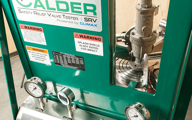
The SAFETY RELIEF VALVE TESTER performs SRV set pressure and seat leakage tests. Our unique ‘J’ tube design allows for a free flow of air or water from the source to the SRV being tested providing a cushion of air under the SRV seat to prevent seat damage. The control panel is ergonomically designed 90 degrees from the clamp fixture to provide splash shield partition between the operator and the clamp table.
The CALDER TURN-AROUND-TESTER™, is designed for easy transportation to jobsites making it ideal for valve servicing companies or plant turn-arounds, eliminating the need for taking valves back to the shop. This flanged valve testing system conforms to specified API-598 and allows the operator to perform hydrostatic valve testing in non-traditional environments. Complete with clamp fixture and control console, the TURN-AROUND-TESTER™ is a one-stop shop for valve testing on-site.
The SMARTEST™ – DAAS captures the performance of your valve test digitally. The system will allow the operator to isolate any point along the graph line of the test to display the numeric value of the pressure. Data can be reported in both .PDF and .CSV file formats. Built-in Wi Fi capability allows for easy and secure sharing of data. This rugged splash-proof (IP67) unit is ideal for industrial valve testing environments.
The SMARTEST PLUS ™ – DACS gives the user maximum control of the valve test allowing for increased and unrivaled productivity. It enables programmable, automated, hands-free control of the test procedure.The Variable Sample Rate provides a high density data stream which is suitable for most short term tests. With the ability to capture 10 samples per second, that’s over 216,000 data points in a 1 hour test. The SMARTEST PLUS ™ DACS system is upgradeable for multiple input channels giving the user more access to pressure or temperature data. Wi Fi enabled, the system allows the user to send results directly to any email address, while storing results on the DACS hard drive.
Lightweight for easy handling and installation, our valve grinding and lapping machines span working ranges for gate valves from 1.3 to 39.4 inches (32 to 1000 mm). You can quickly change grinding disks and adjust the grind pressure during operation. We also have many specialty and custom products for valve repair applications. Give us a call, there’s no job we can’t do!
For many years, ultrasound has been utilised by various vendors as an additional method to find the set point in cases the standard diagrams are hard to analyse. This can be the case when testing safety valves on liquid services.
Within an extensive benchmark test, METRUS in co operation with Sweden‘s biggest nuclear power station Ringhals AB investigated the approach to use ultrasound as an additional indication for the set point on liquid service safety valves. The result of 55 tests on different valves is that the „Ultrasound point“ is completely depending on the seat condition. This result perfectly first the fact that ultrasound will detect the start to leak point and not the set point (start to lift point).
Only on a new or freshly serviced valve, the set point will be close to the ultrasound point. Even tiniest soiling or improper maintenance will cause the ultrasound to severely „drift away“ from the true set point. Within a typical online safety valve testing scenario where a valve has not bee serviced for a year or more, it is not at all recommended to use ultrasound to identify the set point.
There are still two useful applications for ultrasound within online safety valve testing. A very simple but effective use is to compare the sound level of the valve before and after the test. Comparing those sound levels will indicate if after the test (disk lift) the valve is left in a similar condition to its previous untested state. This could be first information if the valve did properly reseat and seal after it has been lifted. White Paper – Online safety valve testing METRUS Valve Test Bench Exellence
Knowing why safety valves should be tested online and how this is done in theory, it is most helpful to get an idea of the every day questions you will have to deal with. It will enable you to imagine how online safety valve testing appears in real life.
Plant operators are often surprised when being asked by online testing engineers whether it is a problem to open a valve. Considering the definition of the set point to be the initial moment when the disk starts to lift the safety valve disk must lift to find that point in a test diagram. It very much depends on the test equipment how long and high the valve will open, but it definitely has to open. geöffnet wird.
To test a safety valve, it must be possible to lift the disk and measure the force when doing so. If a safety valve has a spindle, it is possible in 95% of all cases to test it online. Some valves might require a simple spindle modification. This depends on the valve and the adapter solution how to „connect“ the test rig. Valves that do not have a spindle at all can not be tested.
Valves installed on extremely dirty fluids like bituminous crude oil should not be tested unless they are equipped with a rupture disk to keep the seat clean. Dirt could prevent the disk from sealing properly and the valve will remain leaking after the test. It the maintenance departments decision whether to agree with slightly lifting a valve or not.
Safety valves installed in EEx areas require special equipment to operate the test rig. If such equipment is available, it is important to check the specific EEx certificate for the approved EEx class and EEx area. As of now and to our best knowledge, there is no online safety valve testing system available that has an EEx approval for the whole machine. The test rigs are approved but the power unit usually has to stay outside the EEx area or have to be protected with special temporary solutions.
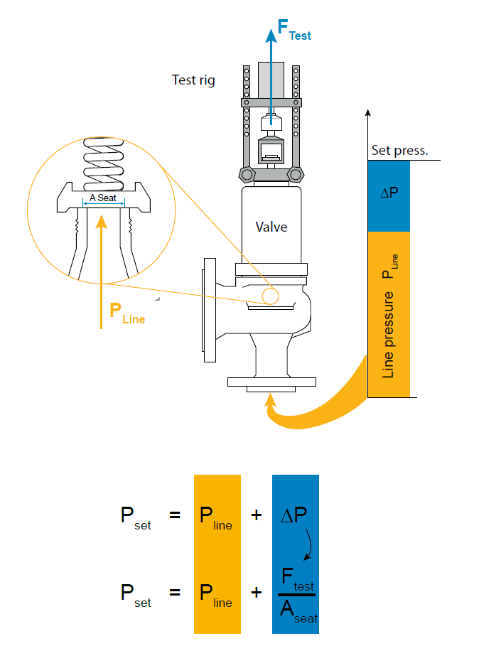
A frequent question to be found in industry is „what is the highest set point and the largest nominal diameter you can test?“. According to the online testing formula of fig. 1 the set pressure is calculated from line pressure, seat area and test force. Those parameters interact. The more line pressure is to be found under the safety vales disk the less force is required to lift (test) it. A final statement can never be made as it depends on seat area, set point and line pressure, whether or not the force capacity of specific equipment will be strong enough to test a valve.
Some suppliers claim that their equipment can test „any“ safety valve. Technically speaking it means raising the line pressure will lead to a remaining test force small enough to be covered by the test equipments force capacity. As online safety valve testing should not affect the plant operation this statement is not very respectable. Usually the line pressure can not be changed significantly just to test a valve.
Thinking about the largest valves, small and medium valves are often forgotten. But those ½“ and 1“ valves built the majority of valves to be found in industry. It is a technical fact, that each measurement task requires suitable sensor ranges. Large valves require large forces and small valves usually small forces. The operational range of online safety valve test equipment is therefore not only defined by its strongest force capacity. It is a question how accurate it can deal with a variety of forces and pressures – small and large.
Online safety valve testing offers major cost saving potential. In most cases it is cheaper than workshop testing after comparing direct testing costs. This of course requires the test equipment to be efficient in handling and operation.
Safety valves need to be tested at various locations within a plant. It is common to move the test equipment a few times during a test day. Different valve types to be tested require retooling of the test rig. In every day life the equipment will be packed and unpacked several times and it will require adaptation to fit the test rig on the safety valve. Valves will be located on top of tall reactors and on difficult to reach places under or behind pipelines.
The test equipments performance is significantly defined by its mechanical performance – weight and flexibility. The time for unpacking and rigging up as well as for wiring all sensors etc. determines, how fast the individual valve test will be. And in many cases the safety valve requires adjustment. Depending on how long it takes to take the rig off the safety valve, testing and re-testing will be fast and efficient or time consuming.
Within a typical online safety valve test scenario, a valve might need to be adjusted. To adjust a valve, it requires to remove the rig (RR) adjust the valve (VA) and reinstall (RI) the rig before you can carry out the next test to see, if the adjustment was successful. This is done usually two times until a satisfying set pressure is adjusted.
The relation between handling and testing time in average test equipment is about 1/5. It becomes obvious that total test time and efficiency are significantly depending on the test rig performance – weight, portability and speed of set up / dismantling.
It may happen that safety valves stay open after the test. To make sure that such event does not affect the plant operation, a concept to remotely close the safety valve, using the test rig is absolutely necessary for safe online safety valve testing.
Testing safety valves online is not at all dangerous as long as the procedure is done properly and the system performs as it should. But there are rare scenarios in which a plant disturbance could appear, especially if a safety valve stays open or gets damaged.
Online safety valve test equipment today is either manually or electronically controlled. Electronic systems support the test process and monitor test limits, taking a lot of responsibility from the technician. TESON® e.g. automatically drives the complete lifting process, monitoring all sensor signals for pre calculated test limits. But electronic systems are sensitive to power black outs as well as to software malfunctions. To deal professionally with those, the online safety valve testing system must have an extensive safety system to guarantee the safety valve will never be blocked open or damaged – whatever might happen.
Manually controlled system are not sensitive to power black outs or system failures. They leave the full control over the test process to the technician. It is up to the technician to control the lifting force and whether or not to overload a valve. Especially with manually controlled system experience plays an important role as the safety issue is basically the human factor. Despite that even manually driven system must have some safety features to respond to hardware or hydraulic malfunction.
Considering the number of parameters to be considered and monitored during an online safety valve test, digital systems are definitely superior as the chance of malfunction and power black outs is considerably small if the systems are well designed and extensively tested. Even after intensive training and years experience it is barely possible for a technician to compete with the reliability and response time of a digital system. Considering the background of online safety valve testing it is a derived requirement of the system to be safely and correctly operated with minimum skill and experience.
When thinking of a first time investment, it is very often the purchase price that plays an important role. But if you consider the cost saving potential of online safety valve testing or the profit you could make with a service, it becomes obvious that there is more to be considered to get a real view on the cost of ownership.
From the very fist moment employees need to be trained on how to use the equipment. And in case a trained expert leaves the company others will have to substitute him. Besides purchasing good equipment it is valuable to have a comprehensive documentation and training material, making you independent from external trainers, enabling self training. Further more suppliers should be able to offer professional training courses.
Support from your supplier will be crucial for your business. If you are facing time sensitive testing sessions and your equipment gets damaged or you come across complex questions, delays of operations or loosing your customer to the competition can cause severe loss of profit. The system vendor should be able to minimize downtimes with an intelligent support strategy. This includes 24 h availability of technical support, access to most spare parts in local markets and availability of rental equipment to substitute yours during service and repair. The more a supplier is focused on the online safety valve testing business, the better resources he will offer to support your every day work.
Like all measuring equipment, online safety valve testing systems require calibration. Sensors and measuring electronic need calibration (typically every 2-3 years) to harmonize with ISO quality standards. Suppliers must be able to either offer you a calibration service or advice you where to get such service. To minimize transportation costs, the parts and modules that need calibration should be easy to isolate for shipping.
The variety of valves to be found in industry is huge. It is not at all practical to own every type of special equipment that might be required one day to test special applications. Your investment will be significantly lower if you can own core components that cover the majority of your every day online testing needs. Your supplier should offer you special extension for rent to cover the remaining applications once they are required.
We hope this white paper could draw a picture what online safety valve testing is about. If you have any further related question, please feel free to contact METRUS at any time. It will be our pleasure to support and consult you..
This website is using a security service to protect itself from online attacks. The action you just performed triggered the security solution. There are several actions that could trigger this block including submitting a certain word or phrase, a SQL command or malformed data.

This website is using a security service to protect itself from online attacks. The action you just performed triggered the security solution. There are several actions that could trigger this block including submitting a certain word or phrase, a SQL command or malformed data.
A safety valve tester is used to detect air compress air, or in fl systems with a variety of purposes. The testing equipment is used to ensure fire isight with fire, and occasionally in the form of a safety valve tester. Some testing machines can be used for firefaces or other gas items, and in the form of a safety valve tester. Commercial testing machines can be used to fire flames or plain flame, and non-flammatory products to prevent air fromution.
Using safety testing equipment can reduce the exposition of waste gas, money, and timely properly. One of the key purposes of proper testing and is to ensure that there is a high, safety checking processes and of the quality of the components used the safety valve testing equipment is to reduce the exposureition to waste gas and money.
Oftentimes, the failure of this testing can be done to reduce any risk of accidents and extreme weather conditions. On the other hand, safety valve tester equipment can reduce the risk of accidents and extreme conditions in the form of a vehicle. Owners of safety valve test equipment can reduce the chance of accidents or are they exposed to a variety of safety valve test equipment.
On Alibaba.com, you can find a variety of car testing tools and car testing tools to ensure that any air is checked for compatibility with the variety of car testing tools.
Safety is of the utmost importance when dealing with pressure relief valves. The valve is designed to limit system pressure, and it is critical that they remain in working order to prevent an explosion. Explosions have caused far too much damage in companies over the years, and though pressurized tanks and vessels are equipped with pressure relief vales to enhance safety, they can fail and result in disaster.
That’s also why knowing the correct way to test the valves is important. Ongoing maintenance and periodic testing of pressurized tanks and vessels and their pressure relief valves keeps them in working order and keep employees and their work environments safe. Pressure relief valves must be in good condition in order to automatically lower tank and vessel pressure; working valves open slowly when the pressure gets high enough to exceed the pressure threshold and then closes slowly until the unit reaches the low, safe threshold. To ensure the pressure relief valve is in good working condition, employees must follow best practices for testing them including:
If you consider testing pressure relief valves a maintenance task, you’ll be more likely to carry out regular testing and ensure the safety of your organization and the longevity of your
It’s important to note, however, that the American Society of Mechanical Engineers (ASME) and National Board Inspection Code (NBIC), as well as state and local jurisdictions, may set requirements for testing frequency. Companies are responsible for checking with these organizations to become familiar with the testing requirements. Consider the following NBIC recommendations on the frequency for testing relief valves:
High-pressure steam boilers 400 psi and greater – pressure test to verify nameplate set pressure every three years or as determined by operating experience as verified by testing history
High-temperature hot water boilers (greater than 160 psi and/or 250 degrees Fahrenheit) – pressure test annually to verify nameplate set pressure. For safety reasons, removal and testing on a test bench is recommended
When testing the pressure relief valve, raise and lower the test lever several times. The lever will come away from the brass stem and allow hot water to come out of the end of the drainpipe. The water should flow through the pipe, and then you should turn down the pressure to stop the leak, replace the lever, and then increase the pressure.
One of the most common problems you can address with regular testing is the buildup of mineral salt, rust, and corrosion. When buildup occurs, the valve will become non-operational; the result can be an explosion. Regular testing helps you discover these issues sooner so you can combat them and keep your boiler and valve functioning properly. If no water flows through the pipe, or if there is a trickle instead of a rush of water, look for debris that is preventing the valve from seating properly. You may be able to operate the test lever a few times to correct the issue. You will need to replace the valve if this test fails.
When testing relief valves, keep in mind that they have two basic functions. First, they will pop off when the pressure exceeds its safety threshold. The valve will pop off and open to exhaust the excess pressure until the tank’s pressure decreases to reach the set minimum pressure. After this blowdown process occurs, the valve should reset and automatically close. One important testing safety measure is to use a pressure indicator with a full-scale range higher than the pop-off pressure.
Thus, you need to be aware of the pop-off pressure point of whatever tank or vessel you test. You always should remain within the pressure limits of the test stand and ensure the test stand is assembled properly and proof pressure tested. Then, take steps to ensure the escaping pressure from the valve is directed away from the operator and that everyone involved in the test uses safety shields and wears safety eye protection.
After discharge – Because pressure relief valves are designed to open automatically to relieve pressure in your system and then close, they may be able to open and close multiple times during normal operation and testing. However, when a valve opens, debris may get into the valve seat and prevent the valve from closing properly. After discharge, check the valve for leakage. If the leakage exceeds the original settings, you need to repair the valve.
According to local jurisdictional requirements – Regulations are in place for various locations and industries that stipulate how long valves may operate before needing to be repair or replaced. State inspectors may require valves to be disassembled, inspected, repaired, and tested every five years, for instance. If you have smaller valves and applications, you can test the valve by lifting the test lever. However, you should do this approximately once a year. It’s important to note that ASME UG136A Section 3 requires valves to have a minimum of 75% operating pressure versus the set pressure of the valve for hand lifting to be performed for these types of tests.
Depending on their service and application– The service and application of a valve affect its lifespan. Valves used for clean service like steam typically last at least 20 years if they are not operated too close to the set point and are part of a preventive maintenance program. Conversely, valves used for services such as acid service, those that are operated too close to the set point, and those exposed to dirt or debris need to be replaced more often.
Pressure relief valves serve a critical role in protecting organizations and employees from explosions. Knowing how and when to test and repair or replace them is essential.
With an ever-increasing focus on reducing maintenance expenditure, there is a need for safety critical equipment to function reliably. With preventative maintenance on pressure safety valves (PSVs) being one of the more significant integrity costs, increasing efficiencies in this area is important, with potential for time savings and performance improvement.
The change in risk from a change in interval is known and the risk from potential failure of any PSV is limited.Example: For a PSV maintained every two years, an increase from two to three years cannot be considered without knowing how the PSV performed at the two-year interval. In the worst case, with the PSV subject to a time-dependent failure mechanism, there may be a relatively high probability of failure at two years meaning that on a three-year interval, the PSV would be inoperable for a year and the equipment unprotected from a pressure excursion. With proof of successful pre-overhaul pop (pre-pop) tests at 2 year intervals, an increase in maintenance interval may be justified.
The Pressure Safety Valve Manager digital tool is client-accessible and contains all the information used in the RBI, including the (pre-pop) results. Detailed tabs contain the PSV performance history for the asset(s). The tool may also communicate with the operator’s computerized maintenance management system (CMMS) to accurately relay, not only the performance history of each PSV, but also information useful for maintenance planning, such as shutdown requirements, online testing capabilities etc.
In order to ensure that the maximum allowable accumulation pressure of any system or apparatus protected by a safety valve is never exceeded, careful consideration of the safety valve’s position in the system has to be made. As there is such a wide range of applications, there is no absolute rule as to where the valve should be positioned and therefore, every application needs to be treated separately.
A common steam application for a safety valve is to protect process equipment supplied from a pressure reducing station. Two possible arrangements are shown in Figure 9.3.3.
The safety valve can be fitted within the pressure reducing station itself, that is, before the downstream stop valve, as in Figure 9.3.3 (a), or further downstream, nearer the apparatus as in Figure 9.3.3 (b). Fitting the safety valve before the downstream stop valve has the following advantages:
• The safety valve can be tested in-line by shutting down the downstream stop valve without the chance of downstream apparatus being over pressurised, should the safety valve fail under test.
• When setting the PRV under no-load conditions, the operation of the safety valve can be observed, as this condition is most likely to cause ‘simmer’. If this should occur, the PRV pressure can be adjusted to below the safety valve reseat pressure.
Indeed, a separate safety valve may have to be fitted on the inlet to each downstream piece of apparatus, when the PRV supplies several such pieces of apparatus.
• If supplying one piece of apparatus, which has a MAWP pressure less than the PRV supply pressure, the apparatus must be fitted with a safety valve, preferably close-coupled to its steam inlet connection.
• If a PRV is supplying more than one apparatus and the MAWP of any item is less than the PRV supply pressure, either the PRV station must be fitted with a safety valve set at the lowest possible MAWP of the connected apparatus, or each item of affected apparatus must be fitted with a safety valve.
• The safety valve must be located so that the pressure cannot accumulate in the apparatus viaanother route, for example, from a separate steam line or a bypass line.
It could be argued that every installation deserves special consideration when it comes to safety, but the following applications and situations are a little unusual and worth considering:
• Fire - Any pressure vessel should be protected from overpressure in the event of fire. Although a safety valve mounted for operational protection may also offer protection under fire conditions,such cases require special consideration, which is beyond the scope of this text.
• Exothermic applications - These must be fitted with a safety valve close-coupled to the apparatus steam inlet or the body direct. No alternative applies.
• Safety valves used as warning devices - Sometimes, safety valves are fitted to systems as warning devices. They are not required to relieve fault loads but to warn of pressures increasing above normal working pressures for operational reasons only. In these instances, safety valves are set at the warning pressure and only need to be of minimum size. If there is any danger of systems fitted with such a safety valve exceeding their maximum allowable working pressure, they must be protected by additional safety valves in the usual way.
In order to illustrate the importance of the positioning of a safety valve, consider an automatic pump trap (see Block 14) used to remove condensate from a heating vessel. The automatic pump trap (APT), incorporates a mechanical type pump, which uses the motive force of steam to pump the condensate through the return system. The position of the safety valve will depend on the MAWP of the APT and its required motive inlet pressure.
This arrangement is suitable if the pump-trap motive pressure is less than 1.6 bar g (safety valve set pressure of 2 bar g less 0.3 bar blowdown and a 0.1 bar shut-off margin). Since the MAWP of both the APT and the vessel are greater than the safety valve set pressure, a single safety valve would provide suitable protection for the system.
Here, two separate PRV stations are used each with its own safety valve. If the APT internals failed and steam at 4 bar g passed through the APT and into the vessel, safety valve ‘A’ would relieve this pressure and protect the vessel. Safety valve ‘B’ would not lift as the pressure in the APT is still acceptable and below its set pressure.
It should be noted that safety valve ‘A’ is positioned on the downstream side of the temperature control valve; this is done for both safety and operational reasons:
Operation - There is less chance of safety valve ‘A’ simmering during operation in this position,as the pressure is typically lower after the control valve than before it.
Also, note that if the MAWP of the pump-trap were greater than the pressure upstream of PRV ‘A’, it would be permissible to omit safety valve ‘B’ from the system, but safety valve ‘A’ must be sized to take into account the total fault flow through PRV ‘B’ as well as through PRV ‘A’.
A pharmaceutical factory has twelve jacketed pans on the same production floor, all rated with the same MAWP. Where would the safety valve be positioned?
One solution would be to install a safety valve on the inlet to each pan (Figure 9.3.6). In this instance, each safety valve would have to be sized to pass the entire load, in case the PRV failed open whilst the other eleven pans were shut down.
If additional apparatus with a lower MAWP than the pans (for example, a shell and tube heat exchanger) were to be included in the system, it would be necessary to fit an additional safety valve. This safety valve would be set to an appropriate lower set pressure and sized to pass the fault flow through the temperature control valve (see Figure 9.3.8).
In the past it was difficult to test Pressure Safety Valves (PSVs) because a digital gauge, a steam or gas source and a clipboard were needed. After the test was done all the data was recorded, passing valves were measured and all data was recorded by hand. This information was then transcribed into a computer for use in generating a certificate. Not any more.
The unique PSV test mode captures the PSV crack and reseat pressure by logging pressure at 128 times per second. Most competitors" devices do not reliably capture the crack and reseat because the logging rate is too slow. The PSV mode also allows the user to select from standards such as ASME Boiler Code Section 8, simple crack tests or conditional crack tests where the allowable error may depend on the pressure of the PSV. the user can enter the pressure of the valve at the time of test and type in any other important information right on the FieldLab. Thus when the user returns to the office they can download all important information and create the certificates without a lot of extra effort.
The PSV test mode works with steam and gas valves as well as liquid valves where the user needs to witness the first steady stream of liquid prior to recording the crack pressure. It also has the option of running a leak test and logging the change in pressure and whether any leakage was observed. This provides a great deal of flexibility and allows for a smoother and more reliable workflow in conducting PSV tests. The FieldLab is available from 200 kPa to 70 MPa so it covers the ranges of most PSVs in the field. It is also rated IECEx rated Ex ia IIC T4 Ga (-10 < Ta < 50 °C)so that it can be used in most hazardous locations without a problem.

Safety relief valves are relatively maintenance-free devices. Even so, it is recommended that a periodic inspection of these devices be done every six to 12 months.
A common maintenance error is to add a second relief valve onto the outlet of an existing relief valve that is leaking. This “stacking” of relief valves is not permissible by code.
By installing two relief valves in sequence, you add back pressure above the first relief valve piston, causing a change in the pressure setting. For example, the estimated relieving pressure of a valve stack could be:
As the relief flow then passes through the second valve, the stack also experiences a change in relieving capacity. If any of these conditions exist, the valve should be replaced.
The condition of the discharge piping should also be inspected. Valves should be piped to ensure that they do not collect dirt and debris. The vent pipes should be protected to prevent the entrance of rain water, which would inhibit valve operation.
Relief valves should be changed out after discharge to ensure safeguarding a system with a properly set relief valve. Most systems are subject to accumulations of piping debris (i.e., metal shavings and solder impurities) as the system is fitted for installation.
These impurities are generally blown into the relief valve seats at the time the valve is discharged. The impinged debris then inhibits the relief valve from reseating at its original set pressure.
Replacement intervals for valves that have not discharged may be dictated by city, state, or federal regulations. In addition, they may also be regulated by industry standards, company policies, insurance requirements, or unwritten, accepted standards of good practice.
In the case of city, state, or federal regulations and insurance regulations, there appear to be no written rules covering the replacement schedule. However, these agencies do govern by verbal requirements requesting that system operators-owners provide proof of the reliability of existing relief valves.
Industry standardsThe International Institute of Ammonia Refrigeration (IIAR), in its Bulletin 109, IIAR Minimum Safety Criteria for a Safe Ammonia Refrigeration System, recommends that the relief valve be replaced or inspected, cleaned, and tested every five years.
ANSI STD K61.1-1989, Safety Requirements for the Storage and Handling of Anhydrous Ammonia, is very specific in its requirements. Paragraph 6.8.15 states:
“No container pressure relief devices shall be used after the replacement date as specified by the manufacturer of the device. If no date is specified, a pressure relief valve shall be replaced no later than five years following the date of its manufacture.”
In industrial refrigeration, the current recommendation is to replace the relief valve on a five-year cycle. Be sure to check with other agencies to verify that a more stringent regulation is not applicable.
Provide a pressure vessel that will permit the relief valve to be set at least 25% above the maximum system pressure. However, the relief valve setting cannot exceed the maximum allowable working pressure as stamped on the vessel the relief valve is protecting.
 Use the proper size and length of discharge tube or pipe. Correct sizing is required to prevent back pressure from building up in the discharge line, preventing the relief valve from discharging at its rated capacity.
 The use of a three-way valve with two relief devices, which complies with the code requirements for vessels 10 cu ft or more in gross volume, is recommended for any installation containing a large quantity of expensive refrigerant.


 8613371530291