
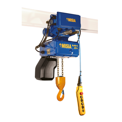
misia wire rope hoists price
Produced to ISO standards and complying with machinery directives they have the CE mark too so you can be assured of quality when purchasing a Misia wire rope hoist.
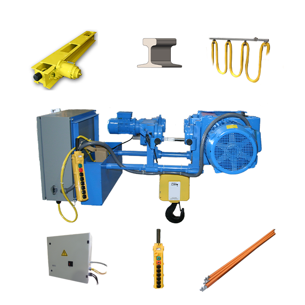
Misia hoists are completely configurable to the customers requirements with many component variations and special features available. Take a look at the full range of wire rope hoists to find you ideal industrial lifting hoist. Lifting Gear Direct is happy to supply the latest XM range of Misia hoists at great prices.

With more than 100’000 units sold and over 30 years experience –Misia has met the high standards expected from a leading wire rope hoist manufacturer. A proven engineered design – dedicated to low maintenance costs, Misia’s high level of reliability and performance whilst remaining cost effective, are all complemented by the impressive fem (ISO) ratings.
Our Misia wire rope hoists can be integrated for use in plants, machinery, or as lifting solutions with electronic controls that are optimized for crane applications, our Misia wire rope hoists cover a wide range of functions efficiently & safely lifting loads from 800Kg weighing up to 50 tonnes.
With more than 100’000 units sold and over 30 years experience – Misia has met the high standards expected from a leading wire rope hoist manufacturer. A proven engineered design – dedicated to low maintenance costs, Misia’s high level of reliability and performance whilst remaining cost effective, are all complemented by the impressive fem (ISO) ratings.
Unlike many of our competitors, Hoist Sales UK carry an extensive stock of Misia hoist units ex our Midlands works. This makes Misia the ideal choice for a replacement hoist unit in a breakdown situation or when a complete Misia crane installation is required within a short timescale.
Misia spare parts and components are also available ex stock at Hoist Sales UK Midlands depot, ensuring that your equipment is operational with the minimum of down time.
Misia"s versatility and reliability, even in the most aggressive environments, make it the ideal hoist for many applications including steelworks, fabrication shops, foundries, galvanizing plants, paper works, dockyards, ports, glassworks etc.
Misia Paranchi have been manufacturing hoists for 30 years from factories in Italy. Now more than 50,000 wire rope hoists are safely operating worldwide. With a solid construction and high quality planetary gear reducers Misia hoists can claim to be amoungst the strongest machines with a good reputation for performance, endurance and competitive prices. All self-braking lift motors pass quality control inspection with both cylindrical and conical versions guaranteeing high performance for intensive use. The "XM" series hoists lift 1 to 50 tons with hook height up to 96mt Misia hoists are equipped with dynamometric pin overload devices and match prescribed industry requirements. Misia"s hoist and trolleys can be equipped with variable frequency drive and a precise control panel, whose fully European components ensure safe installation and high reliability. Misia"s flexible range of both trolley and hoists can provide various layouts to suit the customers requirements. With an experienced team at Misia we can also support you for extended projects such as "crane kits", that may include end-carriages, festoons and bus-bas feeding lines.
When a high degree of accuracy is required to pick or place a load, precise lifting is required and this only facilitated through true vertical lift. Here we have developed a main 5t with an auxiliary 3,2t, both true vertical lift 4/2 hoists lifting height 14m, on a birail trolley with gauge 1707mm. Solution to be placed at 3700 meters above sea level. Other items supplied: control panel for 6 movements, with special AJQ radio remote control with potentiometer, festoon feeding line and busbar line.
At Mizia Hoists, we rise to the occasion with our extensive inventory of high handling rate, cost-effective industrial lifting equipment. We customize our lift solutions for your business needs, from wire rope hoists, electric chain hoists, to our selection of crane components.
Our state-of-the-art equipment is low maintenance even under the most challenging conditions. It can be used as basic hoist units integrated into the worksite, components for a crane set, or other crane applications. Able to lift up to 50 tonnes, our reliable European-made hoists and cranes will get the job done.
See for yourself by browsing through our website or by calling us to get an estimate for a new install. You can also email us with general inquiries about repairing your existing hoists and cranes.

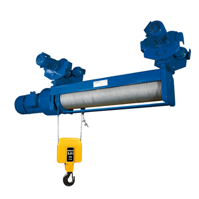
The design of Misia wire rope hoist units is complemented by the use of quality components. All gearboxes are of planetary gear type, 2 or 3 stages and lubricated for life. Motors can be supplied either with cylindrical type with disc brake or tapered rotor conical motors, depending on application or customer preference. The rope guide is manufactured using high quality materials and bearings. Ropes are of high endurance class and galvanized. Monorail low headroom trolleys utilize our twin drive live axel design with planetary geared motors and gearboxes fitted directly onto the drive shaft of the trolley wheels eliminating the need of external gears.
LOW VOLTAGE CONTROL PANEL - As standard MH hoists are complete with integrated low voltage control panel 48V designed, built and wired according to EN 60204-32. The control board is protected inside the hoist aluminium body and sealed with a shock resistant plastic cover complete with rubber gasket to grant IP55 protection. Schneider electromagnetic contactor (low consumption coil) version are used as standard.
Components can be individually engineered to suit different requirements. All our products and components are designed, engineered and manufactured in Europe, in compliance with the European standards (CE mark). MISIA components follow latest innovations in the field of crane building using 35-years experience and know-how of worldwide partners.
2 INDEX MISIA THE COMPANY 2 QUALITY AND CERTIFICATIONS 4 MISIA WIRE ROPE HOISTS XM SERIES 6 Standard configurations 8 Components 10 Performances and technical data 16 Lifting motors 20 Hook blocks 21 STANDARD HOISTS XM Series 22 2 and 4 rope falls 22 5 Supported 5C1 Suspended STANDARD TROLLEY HOISTS XM Series 24 Type 3 monorail standard headroom 24 2 and 4 rope falls Type 83 monorail low headroom 26 2 and 4 rope falls Type 53 - Type 53C1 double beam trolley crab with hoist supported or suspended 28 2 and 4 rope falls EXAMPLES OF APPLICATIONS 30 STATICAL VALUES (dan) 32 2 rope falls 32 4 rope falls 34 SPECIAL APPLICATIONS AVAILABLE 36 1
3 THE COMPANY Misia has manufactured an extensive range of hoists for more than 25 years. Over wire rope units have been sold worldwide and are operational in every sector of industry. 2
4 MISIA The XM series range consists of 7 sizes with capacities between 1000 Kg and Kg. The hoist units are available in different configurations: Low headroom monorail, standard headroom monorail, foot mounted (fixed or suspended), double rail crab units (supported or inverted). With these configurations, this standard range allows the XM series to meet any requirements or application: capacity, hook travel, travel and hoisting speed, load spectrum based on the FEM classification (FEM section IX). All MISIA hoists comply with the Machine Directive 98/37/EEC. 3
5 QUALITY AND CERTIFICATIONS The commercial documentation, together with the technical instruction manuals for the installation, use and maintenance of electric rope hoists, which accompany the sale of every machine, have been drawn up in accordance with unified standards UNI EN 292 parts 1 and 2. The XM series electric rope hoists are produced in accordance with the Machine Directive 89/392/EEC, with the Italian law DPR 459 dated July 24th, 1996 and the Directive 98/37/EEC. The components of the hoist comply with the requirements of the Directive and CE Mark confirms the conformity of the whole equipment. MISIA produces and sells the electric rope hoists under a registered quality control system approved to UNI EN ISO 9002, with issue from the Certification Company BVQI of following international certificates: SINCERT - ITALY. 4
6 MISIA CE MARK The leadership and reliability of MISIA as an electric rope hoist manufacturer are confirmed and guaranteed by our taking on the responsibilities resulting from the CE mark. Before being made available for sale and CE marked, each hoist has all its parts and/or components thoroughly inspected and tested. In addition to the CE declaration of conformity, all the machines have an internal test certificate and are guaranteed for 2 YEARS FROM DELIVERY. 5
7 MISIA WIRE ROPE HOISTS XM SERIES THE RANGE Manufacture of the standard version of XM series wire rope hoists accounts for over 90% of the company s production. This confirms the flexibility of the MISIA product in adapting to many industrial lifting applications without subjecting the user to a bespoke product. The production of the new XM series includes 7 construction sizes for capacities between 1000 Kg and Kg, 2 or 4 rope falls, lifting speeds ranging from 2,5 m/min to 12 m/min, feet mountings allowing supported or suspended fixing (for foot mounted or double rail crab units). A wide range of travelling trolleys are also available in either double or monorail version, with the option of low or standard headroom. 6
9 MISIA WIRE ROPE HOISTS XM SERIES Standard configurations TYPE 5 Foot mounted hoist without trolley. The XM series of Misia wire rope hoist are available in the followings configurations: TYPE 3 Hoist fitted with standard headroom trolley. S2 version (2 rope falls) Lifting capacity from 1000 Kg to Kg either supported or suspended. S4 version (4 rope falls) Lifting capacity from 2000 Kg to Kg either supported or suspended. 8
11 MISIA WIRE ROPE HOISTS XM SERIES Components Hoist gearbox The 2 or 3 stage planetary gearbox reduces the speed of the electric motor to the required rpm of the drum. Each individual planetary gear is manufactured using heat-treated high quality steel. Self braking cylindrical lifting motor The three-phase asynchronous electric motor with cylindrical rotor and disc brake is available in both single or dual speed option. The single polarity motor allows inverter control to be fitted offering further speed control to suit the application requirements. 10
13 Rope guide The rope guide consists of two parts: the guide ring and pressure spring. The pressure spring ensures that the rope sits correctly into the drum groove whilst the guide ring always maintains the rope in the correct position preventing the rope from coming off the drum groove. The guide is a robust steel design fitted with high quality bearings. Movement of the guide across the drum activates the up/down limit switch. Load limiter All XM series hoists with 2 and 4 rope falls are equipped with a load limiter with 2 reaction thresholds. The load limiter consists of an electric-mechanical system with pre-set springs acting on two microswitches located in the auxiliary circuit. These microswitches stop all movements, exception made for the lowering of the load. The first threshold activates a WARNING, the 2nd stops the function. 12
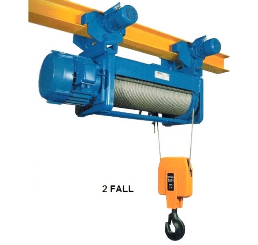
14 MISIA Low headroom trolleys The low headroom trolley consists of two electric trolley motors fitted onto planetary gearboxes. The trolley is of a live axel design with the gearboxes fitting directly onto the drive shaft of the wheels removing the need of external gears. Standard headroom trolleys The standard headroom monorail design enables the hoist to operate directly under and parallel with the crane or runway beam. The hoist is suspended via drive trolley. 13
15 MISIA WIRE ROPE HOISTS XM SERIES Performance Selection of the FEM group is determined by two parameters: a) running time; b) duty. L1 Light duty L2 Medium duty L3 Heavy duty L4 Very heavy duty Hoist seldom lifting the maximum load and mostly light loads. Hoist lifting maximummedium and light loads at an even ratio. Hoists frequently lifting the maximum load and normally medium loads. Hoists regularly lifting loads near the maximum capacity. Comparison FEM-ISO Groups Duty class Running time T L1 - Light duty L2 - Medium duty L3 - Heavy duty L4 - Very heavy duty FEMGroup 1A m 2 m FEM sez. IX 1BM 1Am 2m 3m 4m 5m ISO M3 M4 M5 M6 M7 M8 14
17 MISIA WIRE ROPE HOISTS XM SERIES Characteristics XM 312 N S4 H7 A(A1) /5 a Series Hoist size The design of Misia wire rope hoist units is complemented by the use of quality components. All gearboxes are of planetary gear type, 2 or 3 stages and lubricated for life. Motors can be supplied either with cylindrical type with disc brake or tapered rotor conical motors, depending on application or customer preference. The rope guide is manufactured using high quality materials and bearings. Ropes are of high endurance class and galvanized. Monorail low headroom trolleys utilize our twin drive live axel design with planetary geared motors and gearboxes fitted directly onto the drive shaft of the trolley wheels eliminating the need of external gears. ABBREVIATION OF THE XM RANGE OF MISIA WIRE ROPE HOIST 16 Versions: S2-2 Rope falls S4-4 Rope falls N Normal lifting speed (single) V Fast lifting speed (single) Height of lift Second lifting speed (wherever requested) Type: 5 foot mounted supported 5C1 foot mounted suspended 3 standard headroom monorail trolley 83 low headroom monorail trolley 53 double rail crab trolley with supported hoist 53C1 double rail crab trolley with suspended hoist Second lifting speed (wherever requested) A - cylindrical motor (A1) - conical motor
18 MISIA Technical data Capacity FEM Hoist Rope Hook travel Lifting speed (m/min.) Group type falls (m) 1 speed 2 speed XM Cylindrical motor Conical motor (Kg) H H H H N V N/A V/A N/A1 V/A m 308 2/ /2,6 12/4 8/1,3 12/ m 308 2/ /2,6 12/4 8/1,3 12/ m 308 4/ /1,3 6/2 4/0,7 6/ m 312 2/ /2,6 12/4 8/1,3 12/ m 308 4/ /1,3 6/2 4/0,7 6/ m 312 2/ /2,6 12/4 8/1,3 12/ m 308 4/ /1,3 6/2 4/0,7 6/ m 316 2/ /2,6 12/4 8/1, m 525 2/ /2,6 12/4 8/1,3 12/ m 312 4/ /1,3 6/2 4/0,7 6/ m 525 2/ /2,6 12/4 8/1,3 12/ m 312 4/ /1,3 6/2 4/0,7 6/ m 525 2/ /2,6 12/4 8/1,3 12/ m 316 4/ /1,3 6/2 4/0, m 525 4/ /1,3 6/2 4/0,7 6/ m 740 2/ /2,6-8/ m 525 4/ /1,3 6/2 4/0,7 6/ m 740 2/ /2,6-8/ m 525 4/ /1,3 6/2 4/0,7 6/ m 950 2/ /1, m 740 4/1 7 9, ,5 4-4/1,3-4/ Am 963 2/ /1, Am 740 4/1 7 9, ,5 4-4/1,3-4/ m 950 4/ /0, Am 963 4/ , ,5/0,6 - The lifting and travel speeds refer to a frequency of 50Hz. Hoists travel speed (m/min.) Type 1 speed 2 speed 3 - monorail standard headroom 18 18/ monorail low headroom / double rail /6,5-16/5,3-12/4-10/3,3 For double beam trolley with kg capacity, the max. available speed is 16 or 16/5,3 m/min. 17
19 MISIA WIRE ROPE HOISTS XM SERIES Lifting and trolley motors PERFORMANCES AND CHARACTERISTICS Standard voltages: V V a 50 Hz - For single pole motors, Δ/Y or Y/Δ changeover is always possible. - For twine pole motors specify the exact supply voltage. - The drawings shown in the charts refer to 400V 50Hz. Standard protection class: Motors IP54- Brake IP23. Special Voltages: On demand, special voltages are available. 18
20 MISIA Technical data of the lifting motors with cylindrical rotor (No. of starts/h=240 - I.R. 40% - Aux. speed I.R. 15%) 1 speed 2 speeds XM hoist N V N/A V/A kw A kw A kw A kw A 308 2,5 7,5 4,0 9,5 2,5/0,8 6,0/5,5 4,0/1,33 9,5/ ,0 9,5 5,8 12,5 4,0/1,33 9,5/7,0 5,8/1,9 15/ ,0 12,5 8,0 17 5,0/1,70 13/10 8,0/2,6-18/13, ,0 17,0 12,0 32 8/2,6 18/13,5 12/4-15/ , /4 24/ Technical data of the lifting motors with conical rotor (No. of starts/h=240 - I.R. 40% - Aux. speed I.R. 15%) XM hoist N V N/A1 V/A1 kw A kw A kw A kw A 308 2,5 7,8 4,0 13,1 2,9/0,48 8,1/4,8 4/0,70 10/8, ,0 13,1 5,8 16,5 4/0,70 10/8,0 5,8/1,0 14,5/7, ,8 16,5 8,0 19,2 5,8/1,0 14,5/7, ,0 19,2 12,0 30,0 8/1,3 16/14,3 12/2,0 34/ ,5 38, /3 32/ ,5 38, /3 32/ ,5 38, /3 32/ Technical data of the monorail trolley motors type 3 (No. of starts/h=120 - I.R. 40% - Aux. speed I.R. 15%) Max. capacity 1 speed 2 speeds (kg) kw A kw A ,37 1,7 0,37/0,12 1,7/1, ,55 1,9 0,55/0,18 1,9/1,7 Technical data of the monorail trolley motors type 83 (No. of starts/h=120 - I.R. 40% - Aux. speed I.R. 15%) Max. capacity 1 speed 2 speeds (kg) kw A kw A Up to x 0,18 2x 0,75 2x 0,18/0,045 2x 0,75/0,75 Up to x 0,24 2x 0,85 2x 0,24/0,060 2x 0,85/1,10 Up to x 0,30 2x 1,20 2x 0,30/0,060 2x 1,20/1,20 Up to x 0,60 2x 1,80 2x 0,50/0,130 2x 1,80/1,00 Technical data of the monorail trolley motors type 53 (No. of starts/h=120 - I.R. 40% - Aux. speed I.R. 15%) Max. capacity 1 speed 2 speeds (kg) kw A kw A Up to ,25 0,85 0,25/0,08 0,90/0,95 Up to ,37 1,30 0,37/0,12 1,40/1,40 Up to ,55 1,70 0,55/0,18 1,80/1,90 Up to ,75 2,00 0,75/0,25 2,10/2,50 Up to ,10 3,40 1,10/0,37 3,50/3,50 Up to ,50 3,90 1,50/0,55 3,80/3,80 The Amps of the above chart refer to 400 V - 50 Hz. 19
21 MISIA WIRE ROPE HOISTS XM SERIES Lifting motors Lifting motors - Dimensions Hoist Capacities Cylindrical motors Conical motors XM (t) N V NA VA N V N...A1 V...A1 S2 (2/1) S4(4/1) L D L D L D L D L1 D1 L1 D1 L1 D1 L1 D ,6 2-2,5-3, , ,2 6, , , ,3-8 12, , Self braking motor cylindrical rotor Self braking motor conical rotor 20
22 MISIA WIRE ROPE HOISTS XM SERIES Hook blocks MISIA Hook blocks - Dimensions Hoist Hook blocks S2(2/1) Hook blocks S4(4/1) Rope Capacity Hook Weight Capacity Hook Weight XM diam. (t) H2 H3 C1 B1 n (kg) (t) H H1 A B C n (kg) , ,5-3, , , , , , ,6 25 6, , ,5 35 6, , , , S2 (2/1) S4 (4/1) Hooks DIN
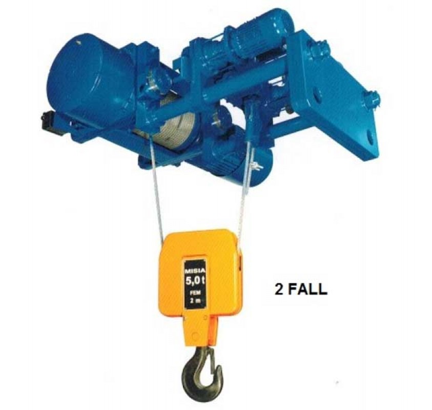
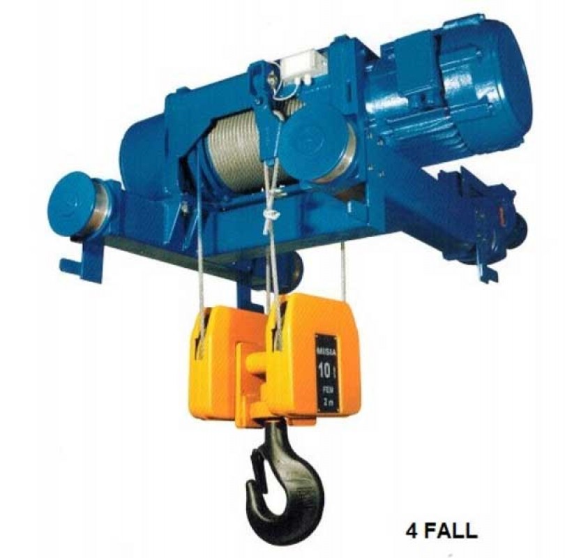
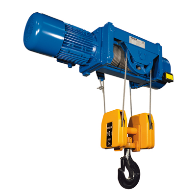
23 STANDARD HOISTS XM SERIES S2 two rope falls (2/1) S4 4 rope falls (4/1) 5 Supported 5C1 Suspended Capacities from 1 t to 10 t XM 308 XM 312 XM 316 XM 525 Capacities from 6,3 t to 25 t XM 740 XM 950 XM
24 MISIA S2 WITH 2 ROPE FALLS (2/1) Hoist Capacity Hook C H a b k s m n f g h1 i h2 l p q r e d1 Weight XM travel t m mm mm mm mm mm mm mm mm mm mm mm mm mm mm mm mm mm mm mm kg , , , , , , , , , , , , , , , , , , , , , , , S4 WITH 4 ROPE FALLS (4/1) Hoist Capacity Hook C H a b k s m n f g h1 i h2 l p q r e d Weight XM travel t m mm mm mm mm mm mm mm mm mm mm mm mm mm mm mm mm mm mm mm kg ,5-3, ,5-3, ,5-3, , , , , , , , ,5-16 9, , , , , , , , , , * L dimensions of lifting motors and hook blocks, see pages Static values of reactions, see pages
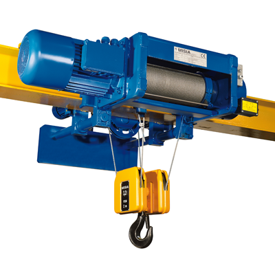
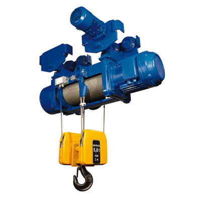
25 STANDARD TROLLEYS Series XM TYPE 3 MONORAIL STANDARD HEADROOM S2 two rope falls (2/1) S4 four rope falls (4/1) Capacities from 1 t to 10 t Larger capacities upon request 24
26 MISIA S2 WITH 2 ROPE FALLS (2/1) Hoist Capacity Hook C H a1 b1 g e d l x f1 f2 i2 h ic q r s Weight XM travel t m mm mm mm mm mm mm mm mm mm mm mm mm mm mm mm mm mm kg , , , , , , , , , , , , , , , , S4 WITH 4 ROPE FALLS (4/1) Hoist Capacity Hook C H a b g e d l x f1 f2 i2 h ic q r s Weight XM travel t m mm mm mm mm mm mm mm mm mm mm mm mm mm mm mm mm mm kg ,5-3, ,5-3, ,5-3, , , , , , , * L dimensions of lifting motors and hook blocks, see pages Static values of reactions, see pages MINIMUM NECESSARY WIDTH OF THE FLAT SIDE OF THE BEAM TO ALLOW THE WHEELS RUN Wheels diameter Min. width
27 STANDARD TROLLEYS Series XM TYPE 83 MONORAIL LOW HEADROOM S2 two rope falls (2/1) S4 four rope falls (4/1) Capacities from 1 t to 10 t Larger capacities upon request 26
28 MISIA S2 WITH 2 ROPE FALLS (2/1) Hoist Capacity Hook C (3) a b d e g h l n m y x t o ic q r s Weight XM travel t m mm mm mm mm mm mm mm mm mm mm mm mm mm mm mm mm mm mm kg , , , , , , , , , , , , , , , , S4 WITH 4 ROPE FALLS (4/1) Hoist Capacity Hook C (3) a b d e g h l n m y x t o ic q r s Weight XM travel t m mm mm mm mm mm mm mm mm mm mm mm mm mm mm mm mm mm mm kg ,5-3, ,5-3, ,5-3, , , , , , , Note: 1) For beam sizes wider than those shown, the C dimension (encumbrance of the hook) increases of 12 mm every 10 mm of wider beam size. 2) The dimension L shown is valid for beam size 300 mm; with different beam size it increases or decreases of half of the difference of the beam size. 3) The values shown are for maximum beam size 300 mm. * L dimensions of lifting motors and hook blocks, see pages Static values of reactions, see pages MINIMUM NECESSARY WIDTH OF THE FLAT SIDE OF THE BEAM TO ALLOW THE WHEELS RUN Wheels diameter Min. width
29 STANDARD TROLLEYS Series XM TYPE 53 - TYPE 53C1 DOUBLE BEAM TROLLEY CRAB WITH HOIST SUPPORTED OR SUSPENDED S2 two rope falls (2/1) S4 four rope falls (4/1) Capacities from 1,6 t to 10 t XM 308 XM 312 XM 316 XM 525 Capacities from 6,3 t to 25 t XM 740 XM 950 XM
30 MISIA S2 WITH 2 ROPE FALLS (2/1) Hoist Capacity Hook Sc C1 H1 C2 H2 d e f g a1 b1 s Pr q r x Weight XM travel t m mm mm mm mm mm mm mm mm mm mm mm mm mm mm mm mm kg 308 1, , , , , , , , , , , , , , , , , , , S4 WITH 4 ROPE FALLS (4/1) Hoist Capacity Hook Sc C1 H1 C2 H2 d e f g a b s Pr q r x Weight XM travel t m mm mm mm mm mm mm mm mm mm mm mm mm mm mm mm mm kg ,5-3, ,5-3, ,5-3, , , , , , , , ,5-16 9, , , , * L dimensions of lifting motors and hook blocks, see pages Static values of reactions, see pages
33 STANDARD HOISTS Series XM S2 (two rope falls) Statical values (dan) SUPPORTED OR SUSPENDED FIG. 5-5C1 XM 308 XM 312 XM 316 XM 525 Hoist Capacity Hook travels XM H10 H14 H20 H26 R1 R2 R3 R4 R1 R2 R3 R4 R1 R2 R3 R4 R1 R2 R3 R4 kg m m m m m m m m m m m m m m m m XM 740 XM 950 XM 963 Hoist Capacity Hook travels XM H14 H19 H26 H33 R1 R2 R3 R4 R1 R2 R3 R4 R1 R2 R3 R4 R1 R2 R3 R4 kg m m m m m m m m m m m m m m m m Hoist Capacity Hook travels XM H20 H32 H48 R1 R2 R3 R4 R1 R2 R3 R4 R1 R2 R3 R4 kg m m m m m m m m m m m m MONORAIL STANDARD HEADROOM FIG. 3 Gearbox side Motor side Load on the single wheel = R1 R2 4 4 Hoist Capacity Hook travels XM H10 H14 H20 H26 R1 R2 R1 R2 R1 R2 R1 R2 kg m m m m m m m m
34 MISIA MONORAIL LOW HEADROOM FIG. 83 Motor side Gearbox side Load on the single wheel = R1 R2 2 2 Hoist Capacity Hook travels XM H10 H14 H20 H26 R1 R2 R1 R2 R1 R2 R1 R2 kg m m m m m m m m DOUBLE BEAM TROLLEY CRAB FIG C1 XM 308 XM 312 XM 316 XM 525 Hoist Capacity Hook travels XM H14 H20 H26 R1 R2 R1 R2 R1 R2 kg m m m m m m XM 740 XM 950 XM 963 Hoist Capacity Hook travels XM H14 H19 H26 H33 R1 R2 R1 R2 R1 R2 R1 R2 kg m m m m m m m m Hoist Capacity Hook travels XM H20 H32 H48 R1 R2 R1 R2 R1 R2 kg m m m m m m
35 STANDARD HOISTS Series XM S4 (four rope falls) Statical values (dan) SUPPORTED OR SUSPENDED FIG. 5-5C1 XM 308 XM 312 XM 316 XM 525 Hoist Capacity Hook travels XM H7 H10 H13 R1 R2 R3 R4 R1 R2 R3 R4 R1 R2 R3 R4 kg m m m m m m m m m m m m XM 740 XM 950 XM 963 Hoist Capacity Hook travels XM H7 H9,5 H13 H16,5 R1 R2 R3 R4 R1 R2 R3 R4 R1 R2 R3 R4 R1 R2 R3 R4 kg m m m m m m m m m m m m m m m m Hoist Capacity Hook travels XM H10 H16 H24 R1 R2 R3 R4 R1 R2 R3 R4 R1 R2 R3 R4 kg m m m m m m m m m m m m MONORAIL STANDARD HEADROOM FIG. 3 Gearbox side Motor side Load on the single wheel = R1 R2 4 4 Hoist Capacity Hook travels XM H7 H10 H13 R1 R2 R1 R2 R1 R2 kg m m m m m m
36 MISIA MONORAIL LOW HEADROOM FIG. 83 Motor side Gearbox side Load on the single wheel = R1 R2 2 2 Hoist Capacity Hook travels XM H7 H10 H13 R1 R2 R1 R2 R1 R2 kg m m m m m m DOUBLE BEAM TROLLEY CRAB FIG C1 XM 308 XM 312 XM 316 XM 525 Hoist Capacity Hook travels XM H7 H10 H13 R1 R2 R1 R2 R1 R2 kg m m m m m m XM 740 XM 950 XM 963 Hoist Capacity Hook travels XM H14 H19 H26 H33 R1 R2 R1 R2 R1 R2 R1 R2 kg m m m m m m m m Hoist Capacity Hook travels XM H20 H32 H48 R1 R2 R1 R2 R1 R2 kg m m m m m m
37 MISIA WIRE HOIST Series XM SPECIAL APPLICATIONS AVAILABLE Lifting heights exceeding those of the standard range S2 two rope falls (2/1) Hoist units with a requirement for extra lifting height can be manufactured in foot mounted, standard monorail, low headroom monorail or double beam trolley versions. Capacities ranging from 1000 kg up to 4000 kg with a lifting height between metres. Capacities ranging from 5000 kg up to 6300 kg with a lifting height between metres. The following configurations are also available: Fig. 43 Articulated standard headroom monorail hoist units to negotiate radius. Lifting capacity up to 4000 kg (minimum radius 1500 mm) Lifting capacity up to kg (minimum radius 2500 mm) Fig. 83B Single rope fall (S1) standard headroom monorail hoist units. Lifting capacities ranging from 800 kg up to 2500 kg with a lifting height between 41 up to 80 metres. Lifting capacities ranging from 3200 kg up to 6300 kg with a lifting height between 49 up to 96 metres. N.B. For the fig. 83B configuration it is necessary to supply a special current reading overload limiter in the electric panel. 36
38 MISIA SPECIAL HOIST WITH SINGLE OUTLET FROM THE DRUM SINGLE HOIST WITH 6-8 ROPE FALLS: With overload limiter type OL Hoist Motor Capacity N of rope falls XM N t 740 NSR6 25 6/1 740 NSR8 32 8/1 950 NSR6 30 6/1 950 NSR8 40 8/1 963 NSR8 50 8/1 SR6 SR8 SR6-SR8 TWIN HOISTS WITH 4+4 ROPE FALLS With pin load cell Hoist Motor Capacity N of rope falls XM N t 2x740 NSR4 32 4/1+4/1 2x950 NSR4 40 4/1+4/1 2x963 NSR4 50 4/1+4/1 37
39 HOISTS XM Series SPECIAL APPLICATIONS AVAILABLE Hoists with double outlet from the drum WITH SINGLE-SIDED DOUBLE ROPE OUTPUT TYPE D1 DOUBLE ROPE OUTPUT WITH 2/1 ROPE FALLS Capacities from 0,4+0,4 t to 3,2+3,2 t TYPE D2 DOUBLE ROPE OUTPUT WITH 4/2 ROPE FALLS Capacities from 1 t to 12,5 t 38
40 MISIA WITH OPPOSITE DOUBLE ROPE OUTPUT TYPE DC1 OPPOSITE DOUBLE ROPE OUTPUT WITH 2/1+1 ROPE FALLS Capacities from 0,4+0,4 t to 3,2+3,2 t TYPE DC2 OPPOSITE DOUBLE ROPE OUTPUT WITH 2/2+2 ROPE FALLS Capacities from 0,8+0,8 t to 6,3+6,3 t 39
41 All rights reserved, especially the rights of reproduction, diffusion, processing and translation. The data and instructions contained in this catalogue are informative and do not bind the responsibility of MISIA PARANCHI Srl for any inaccuracies. MISIA PARANCHI Srl reserves the right to introduce any changes to the products that should be necessary or convenient. MISIA PARANCHI srl reserves the right to introduce without prior advice any modifications for convenience to optimize the products. Descriptions and drawings are not binding, but illustrative
All of our hoists are manufactured to the highest standards for enhanced safety and long term reliability. We also install and maintain the hoists if required. Please see our advice notes for guidance in the selection of the right type and size of hoist to suit your particular requirements.
March Madness Sale up to 30% OFF LIST PRICE Yale YK & R&M Spacemaster Wire Rope Hoists! Limited Time Below Cost Pricing on 2 Powerhouse Wire Rope Hoists—Tons of Features, the Most Purchased & the Lowest Headroom Wire Rope Hoists in the USA!https://bit.ly/2UaT0Td
www.misia.com Manual for installation, INDEX operation and maintenance of the wire rope hoists XM Series
2. DESCRIPTION OF THE HOIST/TROLLEY Page 6 2.1 Hoist configuration 6 2.2 Performance and technical features of the hoists with cylindrical/conical motors 8 2.3 Movement trolley features 10 2.4 Versions and standard use 11 2.5 Technical information 12 2.6 Choice of hoist based on FEM units 13
3. INSTALLATION INSTRUCTIONS Page 14 3.1 Installation preparations 14 3.2 Package 14 3.3 Transport and movement 15 3.4 Parts assembly 16 3.5 Mounting trolley Type 3 and 83 16 3.6 Mounting double rail trolley 18 3.7 Block mounting 18 3.8 Electrical equipment 19 3.9 Electrical connections for hoists supplied without equipment 19 3.9.1 Connections with conical hoist motors at 1 or 2 speeds 20 3.9.2 Connections with cylindrical hoist motors with inverter 23 3.9.3 Connections with cylindrical hoist motors at 1 or 2 speeds 24 3.9.4 Connections with travel motors at 1 or 2 speeds 26 3.9.5 Hoist and travel motors absorption 28 3.10 Start-up 29 3.11 Function tests and adjustments 30 3.12 Load testing 32
The manual also contains the following documents:CE conformity declaration or manufacturer declaration; 1.2 IMPORTANT INFORMATIONTest report of the machine, where applicable;Wiring diagrams, where applicable. Before starting any procedure, the relevant section(s) of this instructions manual for theRecipients of this manual activity to perform must be read.This manual has been prepared for: The guarantee of problem-free and of fullThe plant manager, workshop manager or site correspondence of the performances with the manager; planned use strictly depends on the properThe installation technicians; application of all instructions contained in thisThe operator; manual.The maintenance technicians. Reference legislative frameworkThe manual must be left in the safekeeping of a duly The electric wire hoists XM Series and the relevantauthorised person, in an appropriate place where it is movement trolleys comply with the Essential Safetyalways available in best conditions for reference. Requirements pursuant to Annex I of MachineryIn the event of loss or damage, ask for a copy directly Directive 2006/42/EC and are therefore provided withto MISIA PARANCHI srl indicating the code of this a CE Declaration of Conformity pursuant toAnnexmanual. IIA and the CE Mark pursuant toAnnex III of the same Directive.How to use this manual Furthermore, the electric wire hoists XM Series and theThe instructions are accompanied by symbols relevant electric trolleys comply with the Low Voltagefacilitating reading and specifying the various type of Directive 2006/95/EC and the Electromagneticinformation supplied. Compatibility Directive 2004/108/EC.
MISIA manufactures and distributes electric wire hoists Plate types:under the company quality system in compliance with Identification plate for the hoist/trolleythe standards: UNI EN ISO 9001, with the following Hoist and travel motors plateinternational certificates released by the BV test Blocks platecompany: ACCREDIA - Italy. ILE SIM
Any changes, adaptations, etc. to the machine sold in1.3 LIABILITY the future do not oblige the manufacturer to intervene on the previously supplied equipment, nor should the The instructions in this manual do not substitute, manual or the equipment be considered lacking or but only summarise the obligations stated by inadequate. the actual safety and injury prevention laws and regulations. Any integrations to the manual sent by the manufacturer to users must be saved with theWith reference to the content of this instructions relevant manual.manual, MISIA declines any liability in the followingcases:Use non-compliant with national safety and injury prevention laws and regulations:Defective layout of the structures on which the hoist is intended to operate;Failure to read or comply with the instructions in this manual;Faults in the main power supply;Unauthorised changes to the hoist;Use by untrained staff.
2.1 HOIST CONFIGURATION d) with double rail trolley andThe electric hoists were designed and tested according supported orto the FEM calculation rules for lifting equipment. suspendedAccording to the intended operation, the electric hoists hoist.can be:
Lifting mechanism The lifting mechanism is composed of the following assemblies: 1. planetary gear; 2. hoist body; 3. rope drum; 4.coupling; 5. rope guide; 6.block; 7. self-braking electric motor.b) with standard, monorail trolley. Type 3 Hoists 308525
Hoisting motor, self-braking and conical Load limiterThree-phase asynchronous 1 or 2 speed electric motor All the hoists in the "XM" Series with 2 and 4 rope fallswith cone rotor and integrated cone brake driven by a are systematically equipped with a load limiter.coil spring. The brake is released due to axial sliding of The load limiters intervene on the auxiliary circuitthe rotor after power is switched on. by signalling the maximum nominal load and, in the event of overcharging, stops the ascent operation andHoisting and travel motor, self-braking movement.and cylindrical A Electronic device with dynamometric pin withThree-phase asynchronous, 1 or 2 speed electric relevant pre-calibrated board, with two interventionmotor with cylindrical rotor, with a DC brake. The thresholds;single polarity motor can be inverter driven to obtain BElectromechanical device with pre-calibratedthe slow speed required as well as the acceleration or spring, with two intervention thresholds.deceleration ramps. Electrical systemCoupling The hoist trolley, where required, can be provided with itThe torque of the motor is transmitted to the shaft of own electrical system which includes: electromagneticthe gearbox by a toothed coupling connected to the switches to control all hoist movement, as well thegearbox shaft. protection fuses against short circuit. The control circuits are low voltage (48/110 volts). A terminal boxPlanetary gear with numbered terminals ensures simplicity and safetyThe two or three stage planetary gear reduces the in the wiring for all external functions.rotation speed of the electric motor to the number ofrotations necessary for the drum.All gears on the gearbox are in heat treated high qualitysteel.
DrumThe drum is driven centrally by the hollow outputshaft on the gearbox. The shaft on the gearbox andthe guide plate on the second stage are supportedon roller bearings on which the drum is installed. Forhoists Type 740-750-950-963-980-1100-1125 thegearbox is located inside the drum.The profile of the rope grooves on the drum aremanufactured in compliance with DIN standards.
Rope guideThe rope guide is essentially composed of two parts: aguide ring and a pressure ring that properly guide therope on the drum grooves. The guide ring maintainsthe rope in position during uncoiling, preventing itcoming off the groove and, when the load swings, isguided by a fixed bar and runs on a roller bearing.
Block with hookThe structure of the block with the 2 or 4 rope fallsallows distribution of the tensile force generated fromthe ropes load. The side covers of the block coveringthe pulleys are strong and shock resistant.
Cylindrical motors Capacity Group Hoist Rope falls Hook stroke Lifting speed/Motor power H H H H N V NA VA kg FEM XM No. m m m m m/min kW * m/min kW * m/min kW m/min kW 1000 3m 308 2/1 10 14 20 26 8 2,5 12 2,5 8/2,6 2,5/0,83 12/4 2,5/0,83 1250 3m 308 2/1 10 14 20 26 8 2,5 12 4 8/2,6 2,5/0,83 12/4 4/1,3 1600 2m 308 2/1 10 14 20 26 8 2,5 12 4 8/2,6 2,5/0,83 12/4 4/1,3 3m 308 4/1 7 10 13 4 2,5 6 2,5 4/1,3 2,5/0,83 6/2 2,5/0,83 2000 3m 312 2/1 10 14 20 26 8 4 12 5 8/2,6 4/1,3 12/4 5/1,6 3m 308 4/1 7 10 13 4 2,5 6 4 4/1,3 2,5/0,83 6/2 4/1,3 2500 2m 312 2/1 10 14 20 26 8 4 12 5,8 8/2,6 4/1,3 12/4 5,8/1,9 2m 308 4/1 7 10 13 4 2,5 6 4 4/1,3 2,5/0,83 6/2 4/1,3 3200 2m 316 2/1 10 14 20 26 8 5 12 7 8/2,6 5/1,6 12/4 7/2,3 3m 312 4/1 7 10 13 4 4 6 5 4/1,3 4/1,3 6/2 5/1,6 4000 3m 525 2/1 10 14 20 26 8 8 12 12 8/2,6 8/2,6 12/4 12/4 2m 312 4/1 7 10 13 4 4 6 5,8 4/1,3 4/1,3 6/2 5,8/1,9 5000 3m 316 4/1 7 10 13 4 4 6 5,8 4/1,3 4/1,3 6/2 5,8/1,9 2m 525 2/1 10 14 20 26 8 8 12 12 8/2,6 8/2,6 12/4 12/4 2m 316 4/1 7 10 13 4 5 6 7 4/1,3 5/1,6 6/2 7/2,3 6300 2m 740 2/1 13 18 25 32 8 12 8/2,6 12/4 3m 525 4/1 7 10 13 4 8 6 12 4/1,3 8/2,6 6/2 12/4 8000 2m 740 2/1 13 18 25 32 8 12 8/2,6 12/4 3m 750 2/1 13 18 25 32 8 12 8/2,6 12/4 2m 525 4/1 7 10 13 4 8 6 12 4/1,3 8/2,6 6/2 12/4 10000 2m 750 2/1 13 18 25 32 8 15 8/2,6 15/5 3m 950 2/1 20 32 48 7,5 16 7,5/2,5 16/5,3 9/3 18/6 3m 740 4/1 6,5 9 12,5 16 4 12 4/1,3 12/4 12500 2m 963 2/1 20 32 48 5 12 7,5 18 7,5/2,5 18/6 2m 740 4/1 6,5 9 12,5 16 4 12 4/1,3 12/4 3m 750 4/1 6,5 9 12,5 16 4 12 4/1,3 12/4 16000 3m 950 4/1 10 16 24 4,5 16 6 20 4,5/1,5 16/5,3 6/2 20/6,5 1Am 980 2/1 20 32 48 5 16 7,5 24 2m 750 4/1 6,5 9 12,5 16 4 15 4/1,3 15/5 20000 3m 950 4/1 10 16 24 4,5 18 6 24 3,8/1,3 16/5,3 4,5/1,5 18/6 2m 1100 2/1 20 24 30 44 4,5 18 4,5/1,5 18/6 2m 963 4/1 10 16 24 2,5 12 3,7 18 3,8/1,3 18/6 25000 1Am 1125 2/1 20 24 30 44 4,6 24 4,5/1,5 22/7,3 32000 1Am 980 4/1 10 16 24 2,5 16 3,7 24 40000 2m 1100 4/1 10 12 15 22 2,3 18 2,3/0,6 18/6 50000 1Am 1125 4/1 10 12 15 22 2,3 24 2,3/0,6 22/7,3
Trolleys Trolley speed and motor power RopeCapacity Group Hoist Monorail Double rail falls Type: 3-43 Type: 83 Type: 53-53C1 kg FEM XM No. m/min kW * m/min kW m/min kW * m/min kW m/min kW * m/min kW m/min kW m/min kW 1000 3m 308 2/1 1250 3m 308 2/1 1600 2m 308 2/1 3m 308 4/1 2000 3m 312 2/1 3m 308 4/1 2500 2m 312 2/1 0,37 0,37/0,12 2m 308 4/1 20 2x0.24 20/5 2x0.24/0.06 3200 0,37 0,37/0,12 0,37 0,37/0,12 2m 316 2/1 3m 312 4/1 4000 3m 525 2/1 2m 312 4/1 5000 3m 316 4/1 18 18/6 2m 525 2/1 2m 316 4/1 6300 2m 740 2/1 3m 525 4/1 20 2x0.30 20/5 2x0.30/0.07 0,55 0,55/0,18 8000 1Am 740 2/1 16 16/5,3 20 20/6,5 2m 750 2/1 0,55 0,18/0,55 0,55 0,55/0,18 2m 525 4/1 20 2x0.30 20/5 2x0.30/0.07 10000 1Am 750 2/1 2m 950 2/1 2x0.37 2x0.37/0-12 2m 740 4/1 12500 1Am 963 2/1 1Am 740 4/1 0,75 0,75/0,25 1,1 1,1/0,37 2x0.55 2x0.55/0.18 2m 750 4/1 16000 3m 950 4/1 1Am 980 2/1 2m 750 4/1 20 2x0.75 20/6,5 2x0-75/0.25 20000 2m 950 4/1 2m 1100 2/1 1,1 1,1/0,37 1,5 1,5/0,55 1Am 963 4/1 25000 1Am 1125 2/1 32000 1Am 980 4/1 20 2x1.1 20/6,5 2x1.1/0.37 2x1.1 2x1.1/0.37 2x1.1 2x1.1/0.37 40000 2m 1100 4/1 2x1.5 2x1.5/0.55 2x1.5 2x1.5/0.55 50000 1Am 1125 4/1
S2 - 2 ROPE FALLS (2/1) S2 - 4 ROPE FALLS (4/1) D2 - 4 ROPE FALLS (4/2) CENTRAL FALL
Version: S2 - 2 rope falls 2/1 S4 - 4 rope falls 4/1 D2 - 4 rope falls 4/2 Type: 5 supported 5C1 suspended 3 standard monorail trolley 83 low headroom monorail trolley 53 double rail trolley with rested hoist N 1 speed normal lifting 53C1 double rail trolley with suspended hoist V 1 speed fast lifting
2.5 TECHNICAL INFORMATION Standard guards and insulation MISIA hoists are designed for use in an environment protected from atmospheric agents. Electrical parts areReference legislative framework supplied with the guards and insulation as indicated inThe design and construction of the electric rope hoists Tables 1, 2 and 3."XM" Series and the relevant movement trolleys tookinto consideration the following main standards and Conical motors Table 1technical regulation: Guard Class of EN ISO 12100:2010 Main fundamental Function Motor Brake insulation general design concepts. Lifting IP54 IP23 FEN ISO 13849-1:2008 Parts of the command system Movement IP54 IP23 F relating to safety. EN 12385-4:2008 Steel ropes - Safety Part 4 - Stranded ropes for general lifting use. Cylindrical motors Table 2 EN 13135-1:2010 Lifting devices Part 1 - Electrical and technical equipment. Guard Class of Function Motor Brake insulation EN 13135-2:2010 Lifting devices Lifting IP55 IP55 F Part 2 - Non-electrical and technical equipment. Movement IP55 IP55 F EN 12077-2:2008 Limiting and indication devices. EN 13001-1:2009 Lifting equipment - General criteria for the project Part 1 - Principles and main requirements. Electrical systems Table 3 EN 13001-2:201.1 Lifting equipment - Max insulation Part Guard General criteria for the project voltage Part 2 - Load actions. Electric box IP55 1,500 V EN 13001-3-1:2012 Lifting equipment - Cables CE 120/22 450/750 V General criteria for the project Connectors IP55 600 V Part 3-1 - Limit statuses. Keypad IP55 500 V EN 14492-2:2009 Lifting equipment - Limit switch IP54 500 V Part 2 - Motorised hoists. EN 60204-32:2008 Safety of electrical equipment Hoists for outdoor use, guards and insulation other on lifting machinery. than standard ones are available on request. EN 60529:1997 Level of casing protection (lP Codes). ISO 4301-1:1988 Lifting equipment - Classification - Part 1 - General information. ISO 4308-1:2003 Lifting equipment - Rope selection - Part 1 - General information. Noise The sound pressure level emitted when all the parts DIN 15400 Selection of lifting hooks - Mechanical and support properties. of the hoist are working is clearly under 85 dB(A) measured 1 m distance and 1.60 metres off the ground. DIN 15401 Selection of lifting single hooks. FEM 1.001/98 Calculation of lifting equipment. FEM 9.511/86 Classification of mechanisms. Electrical power supply Serial MISIA hoists are designed for three-phase FEM 9.661/86 Selection of drums, ropes and pulleys. AC power 230/400Volt / 50Hz 10% for one speed FEM 9.683/95 Choice of lifting motors or 400Volt / 50Hz 10% for two speed motors. and travel motors. FEM 9.755/93 Safe work periods. The design of the power supply line must be adequate FEM 9.761/93 Load limiters. for the power and absorption of the motor relevant FEM 9.941/95 Command symbols. to configuration of the machine planned in the sales quote (see table 6 on page 29).Operating conditionsThe MISIA standard hoists are manufactured to work Motors for special voltages and frequencies other thanin environmental conditions characterised by: standard supplies are available on request.min. temperature.-10C max +40Crelative humidity < 80%altitude max 1000 a.s.l.When operation of the hoist is planned in otherenvironmental conditions to those standard conditions,special versions are available on request.
% of the chosen duty class (see table). 00 100 100 00 100 100 00 100 100 00 100 100 %%tempo tempodidifunzionamento funzionamento %%tempo tempodidifunzionamento funzionamento %%tempo tempodidifunzionamento funzionamento %%tempo tempodidifunzionamento funzionamento Comparison between duty classes FEM section IX (standard hoists) E For hoists that rarely lift For hoists lifting FEM section I and ISO (special hoists) the maximum load and approximately the mainly reduced loads. same ratio maximum, FEM 9.511 FEM Sect. I-ISO medium and reduced 1C m M2 loads. 1B m M3 1A m M4 2m M5 3m M6 L3Heavy L4 Very Heavy 4m M7 100 100
Group Continuous Max. no. of consecutive running start-ups during FEM ISO time min. the running time 100 0 100 0 100 1B m M3o % tempo di funzionamento % tempo di funzionamento 15 10 1A m M4 2m M5 30 10 For hoists that For hoists that regularly 3m M6 frequently lift the lift loads near the maximum load and maximum value. normally medium loads.
Before starting installation, make sure the Check in the packaging-list, or the delivery technical data of the hoist and the parts to be note, the list of documents supplied with the prepared by the user comply with the content equipment (including the instruction, operation of the order confirmation, in order to ensure a and maintenance manual, the various certificates proper installation, especially: and the conformity declaration). The hoist can be delivered on: pallets, crate, closed case, Verify the suitability of the rail or the fixed according to the requirements of the customer support to hold the hoist, as well as the feeding when making the order. For "closed cases" line. respect the handling instructions as well as the indications and symbols marked thereon.
Provide suitable test weights for dynamic and Before handling the packaging, take note of the static load tests, with suitable sling and lifting weight of the load unit signed on the package equipment, as follows: and use proper tools.
To extract the hoist, hook the slings to the3.3 TRANSPORT AND MOVEMENT points provided, as shown in the illustrations. Using the ring bolts M shown in table A on In order to ensure careful and proper handling page 16. of the equipment, we recommend you entrust qualified carriers with the transport. No other goods can be laid on the equipment or its package. During transport the goods must be properly covered to provide waterproof protection against rain. In case of shipping, the package units must be kept in the hold protected against sprinkling water or humid winds.
To assemble hoists Type 5C1 (suspended type) always use the lock tab under the head of the SC bolt and bend as shown. For the bolt diameter SC see table A.
For any changes please contact the Technical Department of MISIA. h(coupling thickness)
In case of hoists with monorail trolley Type 3 and Type 83, the trolleys are delivered with a pre-set beam width. This value is indicated in the order confirmation Check for compliance and verify the space required on the catalogue.
Nut Low headroom trolleys are available with


 8613371530291