
nominal strength of wire rope factory
Wire rope is always manufactured larger—never smaller—than the nominal diameter when specified in inches. The allowable tolerances are shown in the table.
In standard practice, the nominal diameter is the minimum diameter. All tolerances are taken on the plus side when specified in inches. Wire rope is not termed oversize until its diameter exceeds the allowable maximum. For example, a 1" nominal diameter wire rope may vary between 1" and 1.05" in diameter.
The rope strength design factor is the ratio of the rated strength of the rope to its operating stress. If a particular rope has a rated strength of 100,000 lbs. and is working under an operating stress of 20,000 lbs., it has a rope strength design factor of 5. It is operating at one-fifth or 20% of its rated strength.
Many codes refer to this factor as the "safety factor" which is a misleading term since this ratio obviously does not include many facets of an operation which must be considered in determining safety.
Wire rope is an expendable item—a replacement part of a machine or installation. For economic and other reasons, some installations require ropes to operate at high stresses (low rope strength design factors). On some installations where high risk is involved, high rope strength design factors must be maintained. However, operating and safety codes exist for most applications and these codes give specific factors for usage. When a machine is working and large dynamic loadings (shock loadings) are imparted to the rope, the rope strength design factor will be reduced, which may result in over stressing of the rope. Reduced rope strength design factors frequently result in reduced service life of wire rope.

Wire rope is identified by its construction, or the number of strands per rope, and number of wires in each strand. For example, the construction 6x25 denotes a 6-strand rope, with each strand having 25 wires. Constructions having similar weights and breaking strengths are grouped into wire rope classifications, such as the 6x19 and 6x37 Classes.
The term brightrefers to a wire rope manufactured with no protective coating or finish other than lubricant. Some applications do require more corrosion protection than lubricant can provide. In these instances, a galvanized finish is provided. Contact Assembly Specialty for more information on galvanized wire rope.
Improved plow (IPS) steel is strong, tough, durable steel that combines great strength with high resistance to fatigue. Its minimum tensile strength varies from 223 to 258 ksi, depending upon wire diameter. Extra Improved Plow (EIP) steel has a minimum tensile strength that varies from245 to 284 ksi, depending upon wire diameter. Extra Extra Improved Plow (EEIP) steel, is a grade used where a high breaking strength is required. This grade typically provides a breaking strength a minimum of 10% higher than (EIP) and is found primarily as a standard grade for specialized wire rope and often is available for standard wire ropes upon request. Developed for the federal government, Royal Purple Plus is Wirerope Works’ highest strength grade available to Bethlehem Wire Rope customers. RoyalPurplePlusprovides a breaking strength 35% higher than Purple Plus, and is available in Wirerope Works’ Triple-Pac hoist rope. It is the grade of wire which determines the nominal breaking strength for each diameter and construction. Note the acceptance strength listed in the various tables for wire rope products is 2-1/2% below the nominal strengths listed. Other grades are available to meet specific requirements. Some grades are covered by wire rope standards while others may be specially tailored. Contact Assembly Specialty for more information.
Wire rope is a complex mechanical device that has many moving parts all working in tandem to help support and move an object or load. In the lifting and rigging industries, wire rope is attached to a crane or hoist and fitted with swivels, shackles or hooks to attach to a load and move it in a controlled matter. It can also be used to lift and lower elevators, or as a means of support for suspension bridges or towers.
Wire rope is a preferred lifting device for many reasons. Its unique design consists of multiple steel wires that form individual strands laid in a helical pattern around a core. This structure provides strength, flexibility, and the ability to handle bending stresses. Different configurations of the material, wire, and strand structure will provide different benefits for the specific lifting application, including:Strength
However, selecting the proper wire rope for your lifting application requires some careful thought. Our goal is to help you understand the components of a wire rope, the construction of wire rope, and the different types of wire rope and what they might be used for. This will allow you to select the best performing and longest-lasting wire rope for the job at hand.
From childhood, many of us have been conditioned to think of a machine as some device with gears, shafts, belts, cams, and assorted whirring parts. Yet, by the rules of physics, an ordinary pry bar is a simple machine, even though it has only one part.
A wire rope is, in reality, a very complicated machine. A typical 6 x 25 rope has 150 wires in its outer strands, all of which move independently and together in a very complicated pattern around the core as the rope bends. Clearances between wires and strands are balanced when a rope is designed so that proper bearing clearances will exist to permit internal movement and adjustment of wires and strands when the rope has to bend. These clearances will vary as bending occurs, but are of the same range as the clearances found in automobile engine bearings.
Understanding and accepting the “machine idea” gives a rope user a greater respect for rope, and enables them to obtain better performance and longer useful life from rope applications. Anyone who uses a rope can use it more efficiently and effectively when they fully understand the machine concept.
Wires are the smallest component of wire rope and they make up the individual strands in the rope. Wires can be made from a variety of metal materials including steel, iron, stainless steel, monel, and bronze. The wires can be manufactured in a variety of grades that relate to the strength, resistance to wear, fatigue resistance, corrosion resistance, and curve of the wire rope.
Strands of wire rope consist of two or more wires arranged and twisted in a specific arrangement. The individual strands are then laid in a helical pattern around the core of the rope.
The core of a wire rope runs through the center of the rope and supports the strands and helps to maintain their relative position under loading and bending stresses. Cores can be made from a number of different materials including natural or synthetic fibers and steel.
Lubrication is applied during the manufacturing process and penetrates all the way to the core. Wire rope lubrication has two primary benefits:Reduces friction as the individual wires and strands move over each other
The number of layers of wires, the number of wires per layer, and the size of the wires per layer all affect the strand pattern type. Wire rope can be constructed using one of the following patterns, or can be constructed using two or more of the patterns below.Single Layer – The most common example is a 7 wire strand with a single-wire center and six wires of the same diameter around it.
Filler Wire – Two layers of uniform-size wire around a center with the inner layer having half the number of wires as the outer layer. Small filler wires, equal to the number in the inner layer, are laid in valleys of the inner wire.
Seale – Two layers of wires around a center with the same number of wires in each layer. All wires in each layer are the same diameter. The large outer wires rest in the valleys between the smaller inner wires.
Warrington – Two layers of wires around a center with one diameter of wire in the inner layer, and two diameters of wire alternating large and small in the outer later. The larger outer-layer wires rest in the valleys, and the smaller ones on the crowns of the inner layer.
On a preformed wire rope, the strands and wires are formed during the manufacturing process to the helical shape that they will take in a finished wire rope.
Preformed rope can be advantageous in certain applications where it needs to spool more uniformly on a drum, needs greater flexibility, or requires more fatigue-resistance when bending.
Direction and type of lay refer to the way the wires are laid to form a strand (either right or left) and how the strands are laid around the core (regular lay, lang lay, or alternate lay).Regular Lay – The wires line up with the axis of the rope. The direction of the wire lay in the strand is opposite to the direction of the strand lay. Regular lay ropes are more resistant to crushing forces, are more naturally rotation-resistant, and also spool better in a drum than lang lay ropes.
Lang Lay– The wires form an angle with the axis of the rope. The wire lay and strand lay around the core in the same direction. Lang Lay ropes have a greater fatigue-resistance and are more resistant to abrasion.
A fiber core can be made of natural or synthetic polypropylene fibers. Fiber cores offer greater elasticity than a steel core but are more susceptible to crushing and not recommended for high heat environments.
A steel core can be an independent wire rope or an individual strand. Steel cores are best suited for applications where a fiber core may not provide adequate support, or in an operating environment where temperatures could exceed 180° F.
The classifications of wire rope provide the total number of strands, as well as a nominal or exact number of wires in each strand. These are general classifications and may or may not reflect the actual construction of the strands. However, all wire ropes of the same size and wire grade in each classification will have the SAME strength and weight ratings and usually the same pricing.
Besides the general classifications of wire rope, there are other types of wire rope that are special construction and designed for special lifting applications.
Some types of wire rope, especially lang lay wire rope, are more susceptible to rotation when under load. Rotation resistant wire rope is designed to resist twisting, spinning, or rotating and can be used in a single line or multi-part system.
Special care must be taken when handling, unreeling, and installing rotation resistant wire rope. Improper handling or spooling can introduce twist into the rope which can cause uncontrolled rotation.
Compacted strand wire rope is manufactured using strands that have been compacted, reducing the outer diameter of the entire strand, by means of passing through a die or rollers. This process occurs prior to closing of the rope.
This process flattens the surface of the outer wires in the strand, but also increases the density of the strand. This results in a smoother outer surface and increases the strength compared to comparable round wire rope (comparing same diameter and classification), while also helping to extend the surface life due to increased wear resistance.
A swaged wire rope differs from a compacted strand wire rope, in that a swaged wire rope’s diameter is compacted, or reduced, by a rotary swager machine after the wire rope has been closed. A swaged wire rope can be manufactured using round or compacted strands.
The advantages of a swaged wire rope are that they are more resistant to wear, have better crushing resistance, and high strength compared to a round strand wire rope of equal diameter and classification. However, a swaged wire rope may have less bending fatigue resistance.
A plastic coating can be applied to the exterior surface of a wire rope to provide protection against abrasion, wear, and other environmental factors that may cause corrosion. However, because you can’t see the individual strands and wires underneath the plastic coating, they can be difficult to inspect.
Plastic filled wire ropes are impregnated with a matrix of plastic where the internal spaces between the strands and wires are filled. Plastic filling helps to improve bending fatigue by reducing the wear internally and externally. Plastic filled wire ropes are used for demanding lifting applications.
This type of wire rope uses an Independent Wire Rope Core (IWRC) that is either filled with plastic or coated in plastic to reduce internal wear and increase bending fatigue life.
Remember, wire rope is a complex piece of mechanical machinery. There are a number of different specifications and properties that can affect the performance and service life of wire rope. Consider the following when specifying the best type of wire rope for your lifting application:Strength
When you select a piece of rope that is resistant to one property, you will most likely have a trade-off that affects another property. For example, a fiber core rope will be more flexible, but may have less crushing resistance. A rope with larger diameter wires will be more abrasion resistant, but will offer less fatigue resistance.
At Mazzella Companies, we offer all different kinds of wire rope from all of the leading manufacturers. We sell the highest-quality domestic and non-domestic rigging products because product quality and operating safety go hand-in-hand. We have one of the largest and most complete inventories of both domestic and non-domestic rigging and lifting products to suit your lifting needs.
If you’re looking for a standard or custom specified wire rope for your lifting project, contact a Lifting Specialist at a Mazzella Companies location near you.
We stock well over 2,000,000 feet of wire rope in our various locations … ready for immediate delivery! We provide wire rope assemblies, and manufacture bridge cables, crane cables, steel mill cables, and thousands of OEM assemblies.
Some of our calculators and applications let you save application data to your local computer. These applications will - due to browser restrictions - send data between your browser and our server. We don"t save this data.
Wire ropes are essential for safety purposes on construction sites and industrial workplaces. They are used to secure and transport extremely heavy pieces of equipment – so they must be strong enough to withstand substantial loads. This is why the wire rope safety factor is crucial.
You may have heard that it is always recommended to use wire ropes or slings with a higher breaking strength than the actual load. For instance, say that you need to move 50,000 lbs. with an overhead crane. You should generally use equipment with a working load limit that is rated for weight at least five times higher – or 250,000 lbs. in this case.
This recommendation is all thanks to the wire rope safety factor. This calculation is designed to help you determine important numbers, such as the minimum breaking strength and the working load limit of a wire rope.
The safety factor is a measurement of how strong of a force a wire rope can withstand before it breaks. It is commonly stated as a ratio, such as 5:1. This means that the wire rope can hold five times their Safe Work Load (SWL) before it will break.
So, if a 5:1 wire rope’s SWL is 10,000 lbs., the safety factor is 50,000 lbs. However, you would never want to place a load near 50,000 lbs. for wire rope safety reasons.
The safety factor rating of a wire rope is the calculation of the Minimum Break Strength (MBS) or the Minimum Breaking Load (MBL) compared to the highest absolute maximum load limit. It is crucial to use a wire rope with a high ratio to account for factors that could influence the weight of the load.
The Safe Working Load (SWL) is a measurement that is required by law to be clearly marked on all lifting devices – including hoists, lifting machines, and tackles. However, this is not visibly listed on wire ropes, so it is important to understand what this term means and how to calculate it.
The safe working load will change depending on the diameter of the wire rope and its weight per foot. Of course, the smaller the wire rope is, the lower its SWL will be. The SWL also changes depending on the safety factor ratio.
The margin of safety for wire ropes accounts for any unexpected extra loads to ensure the utmost safety for everyone involved. Every year there aredue to overhead crane accidents. Many of these deaths occur when a heavy load is dropped because the weight load limit was not properly calculated and the wire rope broke or slipped.
The margin of safety is a hazard control calculation that essentially accounts for worst-case scenarios. For instance, what if a strong gust of wind were to blow while a crane was lifting a load? Or what if the brakes slipped and the load dropped several feet unexpectedly? This is certainly a wire rope safety factor that must be considered.
Themargin of safety(also referred to as the factor of safety) measures the ultimate load or stress divided by theallowablestress. This helps to account for the applied tensile forces and stress thatcouldbe applied to the rope, causing it to inch closer to the breaking strength limit.
A proof test must be conducted on a wire rope or any other piece of rigging equipment before it is used for the first time.that a sample of a wire rope must be tested to ensure that it can safely hold one-fifth of the breaking load limit. The proof test ensures that the wire rope is not defective and can withstand the minimum weight load limit.
First, the wire rope and other lifting accessories (such as hooks or slings) are set up as needed for the particular task. Then weight or force is slowly added until it reaches the maximum allowable working load limit.
Some wire rope distributors will conduct proof loading tests before you purchase them. Be sure to investigate the criteria of these tests before purchasing, as some testing factors may need to be changed depending on your requirements.
When purchasing wire ropes for overhead lifting or other heavy-duty applications, understanding the safety dynamics and limits is critical. These terms can get confusing, but all of thesefactors serve an important purpose.
Our company has served as a wire rope distributor and industrial hardware supplier for many years. We know all there is to know about safety factors. We will help you find the exact wire ropes that will meet your requirements, no matter what project you have in mind.
Original equipment wire rope and replacement wire rope must be selected and installed in accordance with the requirements of this section. Selection of replacement wire rope must be in accordance with the recommendations of the wire rope manufacturer, the equipment manufacturer, or a qualified person.
Wire rope design criteria: Wire rope (other than rotation resistant rope) must comply with either Option (1) or Option (2) of this section, as follows:
Option (1). Wire rope must comply with section 5-1.7.1 of ASME B30.5-2004 (incorporated by reference, see § 1926.6) except that section"s paragraph (c) must not apply.
Option (2). Wire rope must be designed to have, in relation to the equipment"s rated capacity, a sufficient minimum breaking force and design factor so that compliance with the applicable inspection provisions in § 1926.1413 will be an effective means of preventing sudden rope failure.
Type I rotation resistant wire rope ("Type I"). Type I rotation resistant rope is stranded rope constructed to have little or no tendency to rotate or, if guided, transmits little or no torque. It has at least 15 outer strands and comprises an assembly of at least three layers of strands laid helically over a center in two operations. The direction of lay of the outer strands is opposite to that of the underlying layer.
Type II rotation resistant wire rope ("Type II"). Type II rotation resistant rope is stranded rope constructed to have significant resistance to rotation. It has at least 10 outer strands and comprises an assembly of two or more layers of strands laid helically over a center in two or three operations. The direction of lay of the outer strands is opposite to that of the underlying layer.
Type III rotation resistant wire rope ("Type III"). Type III rotation resistant rope is stranded rope constructed to have limited resistance to rotation. It has no more than nine outer strands, and comprises an assembly of two layers of strands laid helically over a center in two operations. The direction of lay of the outer strands is opposite to that of the underlying layer.
Type I must have an operating design factor of no less than 5, except where the wire rope manufacturer and the equipment manufacturer approves the design factor, in writing.
When Types II and III with an operating design factor of less than 5 are used (for non-duty cycle, non-repetitive lifts), the following requirements must be met for each lifting operation:
A qualified person must inspect the rope in accordance with § 1926.1413(a). The rope must be used only if the qualified person determines that there are no deficiencies constituting a hazard. In making this determination, more than one broken wire in any one rope lay must be considered a hazard.
Each lift made under § 1926.1414(e)(3) must be recorded in the monthly and annual inspection documents. Such prior uses must be considered by the qualified person in determining whether to use the rope again.
Rotation resistant ropes may be used as boom hoist reeving when load hoists are used as boom hoists for attachments such as luffing attachments or boom and mast attachment systems. Under these conditions, all of the following requirements must be met:
The requirements in ASME B30.5-2004 sections 5-1.3.2(a), (a)(2) through (a)(4), (b) and (d) (incorporated by reference, see § 1926.6) except that the minimum pitch diameter for sheaves used in multiple rope reeving is 18 times the nominal diameter of the rope used (instead of the value of 16 specified in section 5-1.3.2(d)).
The operating design factor for these ropes must be the total minimum breaking force of all parts of rope in the system divided by the load imposed on the rope system when supporting the static weights of the structure and the load within the equipment"s rated capacity.
Wire rope clips used in conjunction with wedge sockets must be attached to the unloaded dead end of the rope only, except that the use of devices specifically designed for dead-ending rope in a wedge socket is permitted.
Prior to cutting a wire rope, seizings must be placed on each side of the point to be cut. The length and number of seizings must be in accordance with the wire rope manufacturer"s instructions.
Lifting operations are performed in every area of the iron and steel plant. In these operations, safety is a critical factor, which requires reliable materials. Steel wire ropes are a key element of the lifting operations, since everything depends on their performance.
Steel wire rope is also known as steel cable. It is a type of rope which consists of several strands of steel wire laid (twisted) into a helix. It is a preferred lifting device for several reasons. Its unique design consists of multiple steel wires which form individual strands laid in a helical pattern around a core. This structure provides strength, flexibility, and the ability to handle bending stresses. Different configurations of the material, wire, and strand structure provide different benefits for the specific lifting applications. These benefits include strength, flexibility, abrasion resistance, crushing resistance, fatigue resistance, corrosion resistance, and rotation resistance.
Wires are the basic building blocks of a wire rope. They lay around a ‘centre’ in a specified pattern in one or more layers to form a strand. The strands are helically laid together around a centre, which is typically some type of core, to form a wire rope. The strands provide all the tensile strength to the wire rope. Properties like fatigue resistance and resistance to abrasion are directly affected by the design of strands. Selection of the proper wire rope for a lifting application needs some careful considerations.
Modern wire rope was invented by the German mining engineer Wilhelm Albert in the years between 1831 and 1834 for use in the mining operations. It was quickly accepted because it proved superior to metal chains and ropes made of hemp which were used earlier. Wilhelm Albert’s first ropes consisted of three strands with each strand having four wires. With the change in the needs, the designs of the wire ropes have also undergone major changes with respect to the core, overlay, and the weight requirement etc.
A wire rope is, in reality, a very complicated machine. It consists of a number of precise moving parts, designed and manufactured to bear a definite relation to one another. In fact, some wire ropes contain more moving parts than many complicated mechanisms. For example, a six strand wire rope laid around and independent wire rope core, each strand and core with 49 wires, contains a total of 343 individual wires. All these wires are to work together and move with respect to one another if the rope is to have the flexibility necessary for successful operation. The wires in a wire rope move independently and together in a very complicated pattern around the core as the rope bends. Clearances between wires and strands are balanced when a rope is designed so that proper bearing clearances exist to permit internal movement and adjustment of wires and strands when the rope has to bend. These clearances vary as bending occurs, but are of the same range as the clearances found in the automobile engine bearings.
The primary factor in wire rope performance is selecting a wire rope with the best combination of properties for the job. The service life of that rope can be greatly extended by following a planned program of installation, operation, maintenance, and inspection to avoid its failure. The appropriate time to replace a wire rope in service is frequently determined by counting the number of broken wires in the length of one rope lay.
The terms which help to define the construction and properties of the wire rope are length, size, pre-formed or non pre-formed, direction and type of lay, finish of wires, grade of rope, and type of core. The length of the wire rope is the total number of meters (cut to size) when wrapped around the spool and the size is the specified nominal diameter of the wire rope and is specified in millimeters.
There are three basic components which make up the design of a steel wire rope. These are (i) wires made from steel which form a singular strand, (ii) multi- wire strands laid around a core in a helical pattern, and (iii) the core.
Wires– Wires are the basic and smallest component of the wire rope and they make up the individual strands in the rope. Wires can be made from a variety of metal materials including steel, iron, stainless steel, Monel, and bronze but in the steel wire rope they are made from steel. The wires can be manufactured to predetermined physical properties and sizes and in a variety of grades which relate to the strength, resistance to wear, fatigue resistance, corrosion resistance, and curve of the wire. A pre-determined number of finished wires are helically laid together in a uniform geometric pattern to form a strand. The process is carried out with precision and exactness to form a strand of correct size and characteristics. The wires themselves can be coated but are most commonly available in a ‘bright’ or uncoated finish.
Strands – Strands of the wire rope consist of two or more wires arranged and twisted in a specific arrangement. The individual strands are then laid in a helical pattern around the core of the wire rope. Strands made of larger diameter wires are more resistant to abrasion, while strands made of smaller diameter wires are more flexible. Strands are designed with various combinations of wires and wire sizes to produce the desired resistance to fatigue and abrasion. Normally, a small number of large wires are more abrasion resistant and less fatigue resistant than a large number of small wires. The required numbers of suitably fabricated strands are laid symmetrical with a definite length of lay around a core to form the finished wire rope.
The core – The core of a wire rope is the foundation of a wire rope. It runs through the centre of the rope. Its primary function is to support the wire strands in the rope and to maintain them in their correct relative positions during the operating life of the wire rope. The core supports the strands and helps to maintain their relative position under loading and bending stresses. Cores can be made from a number of different materials including natural or synthetic fibres and steel but in the steel wire rope, the core is made from steel. Steel core provides more support than the fibre core. Steel cores resist crushing, are more resistant to heat, reduce the amount of stretch, and increase the strength of the wire rope.
Steel cores are normally of two types. The first type is wire strand core (WSC). This type of the core is used in case of small diameter ropes and in some rotation resistant wire ropes. The second type of steel core is independent wire rope core (IWRC). The IWRC can be made in a separate operation or during the closing operation of the wire rope. IWRC normally provides increased strength to the rope, greater resistance to crushing, and resistance to excessive heat. IWRC increases the strength of the wire rope by 7 %, increases its weight by 10 %, and decreases the flexibility slightly. These ropes are recommended for use on installations where severe loads are placed on ropes running over sheaves or wound on drums. The wire core can also have a plastic coating.
Cores made of compacted strands have the additional designation (K). An independent wire core made of compacted strands is hence called IWRC (K). A rope closed in a single operation and made out of compacted strands both in the core and the outer strands is called PWRC (K).
Wire ropes and their free rope end rotate to a greater or lesser extent around its longitudinal axis under the influence of tension. Wire ropes having a core lay direction opposite to the lay direction of the outer strands and 3-strand or 4-strand regular lay wire ropes rotate considerably less than wire ropes with the same lay direction of the wire core and the outer strands and wire ropes with fibre cores.
According to VDI 2358, a wire rope is semi rotation-resistant when ‘the wire rope which turns around its longitudinal axis when subjected to unguided load and / or hardly transmits a torque to the attachment at the end in the event of guided rope ends’. According to ISO 21669 and DIN EN 12385-3 ‘a rope is considered to be semi rotation resistant if it rotates at least once and at most four times around its axis at a length of 1,000 x d under a load of 20 % of the minimum breaking force. In terms of rotation angle, the defined limits are between 360 deg and 1,440 deg’.
According to the regulation of VDI 2358, a wire rope is rotation-resistant, when ‘the wire rope, which hardly turns around its longitudinal axis when subjected to unguided load and / or hardly transmits a torque to the attachment at the end in the event of guided rope ends’. According to ISO 21669 and DIN EN 12385-3 ‘a rope is considered to be rotation resistant if it rotates around its axis at most once at a length of 1,000 x d under a load of 20 % of the minimum breaking force. The rotation can be exhibited here in rope closing or rope opening sense. For the rotation angle, this implies between -360 deg and 360 deg’.
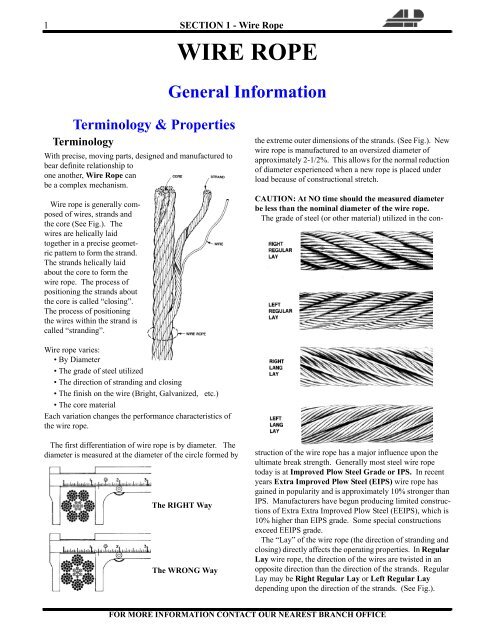
A distinction is made between the nominal rope diameter and the actual rope diameter. The nominal wire rope diameter is an agreed theoretical value for the diameter of the smallest circle enclosing the outer strands. The effective diameter of the wire rope, also called actual rope diameter, is the diameter of the smallest circle enclosing all outer strands, as measured on the rope itself. The tolerance range for the effective rope diameter is specified in related national and international standards. In order to define the correct effective rope diameter, the correct measuring device has to be used. The measurement is to be strictly done over the round ends (circumscribed circle of the rope). If the measurement is done in the strand valleys, the result is inaccurate. For ropes with an uneven number of outer strands, it is important that the measuring surface covers several strands. Fig 1 shows components of a wire rope and measurement of its diameter.
Wire ropes are identified by a nomenclature which is referenced to (i) the number of strands in the rope, (ii) the number (nominal or exact) and arrangement of wires in each strand and (iii) a descriptive word or letter indicating the type of construction i.e. the geometric arrangement of wires.
In the stranding process, initially straight wires are forced into a helical or double-helical form. Hence, the wires in a rope are always under tension, even in an unloaded rope. Such a rope is to be sealed very tightly left and right of the joint before cutting the rope since otherwise the free ends of the wires spring open.
By using a ‘pre-forming tool’, the wires and strands can be heavily plastically deformed during the stranding, so they are laying nearly without tension in the rope, the rope now is pre-formed. The rope producers consider such ropes to be ‘dead’. Pre-formed ropes can be cut much easier, also secured by seizings of course, than non pre-formed ropes.
The wire rope lay is the helix or spiral of the wires and strands. The word ‘lay’ has got three meanings in the rope design. The first two meanings are descriptive of the wire and strand position in the rope. The first meaning describes the direction in which strands rotate around in the wire rope i.e. right lay or left lay. If the strands rotate around the wire rope in a clock wise direction, the rope is said to be right lay. When the strands rotate in the counter-clockwise direction, the wire rope is left lay. The second meaning shows the relationship between the direction strands lay in the wire rope and the direction wire lay in the strands. The third meaning is a length measurement used in manufacturing and inspection. In the third meaning it is the linear length along the rope that a strand makes one complete spiral around the rope core. Lay length is measured in straight line parallel to the centre line of the rope, not by following the path of the strand.
Direction and type of lay refer to the way the wires are laid to form a strand (either right or left) and how the strands are laid around the core (regular lay, lang lay, or alternate lay). Fig 2 shows direction and types of wire rope lay.
Regular lay in the wire rope denotes that the wires are twisted in one direction, and the strand in opposite direction to form the rope. The wires in regular lay line up with the axis of the rope. The direction of the wire lay in the strand is opposite to the direction of the strand lay. Regular lay wire ropes are distinguished between right hand ordinary lay (RHOL) and left hand ordinary lay (LHOL). Due to the difference in direction between the wires and strand, regular lay ropes are less likely to untwist or kink. Regular lay roes are also less subject to failure from crushing and distortion because of shorter length of exposed outer wires. Regular lay ropes are naturally more rotation-resistant, and also spool better in a drum than lang lay ropes. The advantages of regular lay ropes are (i) better structural stability, (ii) higher number of broken wires is allowed, and (iii) identification of broken wires is easier.
Lang lay in the wire rope is the opposite. The wires form an angle with the axis of the rope. The wire lay and strand lay around the core in the same direction. The wires and strands appear to run at a diagonal to the centre line of the rope. Lang lay wire ropes are distinguished between left hand lang lay (LHLL) and right hand lang lay (RHLL). Due to the longer length of the exposed outer wires, lang lay ropes have greater flexibility. These ropes are more likely to twist, kink, and crush. Lang lay ropes have a greater fatigue-resistance and are more resistant to abrasion. The advantages of lang lay ropes are (i) better contact in the groove of the sheaves, (ii) superior resistance to wear, (iii) longer lifetime in case of high dead loads, and (iv) considerably better spooling behaviour on a multi-layer drum
As regards lay direction of a wire rope, a distinction is made between right hand and left hand lay ropes. The lay direction is left hand, when the strands (moving away from the beholder) are rotated counter-clockwise. The lay direction of a rope is right hand, when its strands (moving away from the beholder) are rotated clockwise. The lay direction of a rope is frequently given by a capital S for the left hand lay rope and by a capital Z for the right hand lay rope. Others frequently use abbreviations are RH for right hand lay ropes and LH for left hand lay ropes.
One strand is normally made up of seven to several tens of wires with similar, or differing, diameters in single or multi-layers. In the method where the wires are positioned to form more than two layers, there is the cross lay where the wires of each layer are in the same lay angle, and the parallel lay where one process is used to lay the wires so that the wires of each layer are of the same pitch. For strands of the same diameter, the more is the number of wires, the smaller is the diameter of each wire and the greater is the flexibility of the strand. However, conversely, the rope becomes inferior in its wear resistance nature and its shape deformation nature.
Cross lay – The cross lay is referred to as the point contact lay, as each wire is in contact with each other. The laying of the wires is carried out in such a way that the lay angle is almost equal for each layer of wire of the same diameter. The length of the wires in each layer is also to be the same and the wires of each layer are in contact with each other. Hence, the tension stress which works on the wire becomes uniform, but the bending stress due to the contact points is added and so the fatigue resistance is not as great.
Parallel lay – Parallel lay is also referred to as equal lay. It is also called one operation lay from the number of stranding processes and also as linear contact lay as each wire is in contact with each other. In the parallel lay, the wires of each layer are positioned in such a way that there is no space between them so that the upper layer wires fit neatly into the groove of the lower wires of the strand. For this, wires of differing diameters are positioned at the same time so that each wire layer has the same pitch and is in contact with each other. Hence, parallel lay rope differs from the cross lay rope, although the lay angle of each wire layer and the length of the wires are not uniform, as each wire is in contact with each other, it is superior in its fatigue resistance nature.
The fill factor of a rope is defined as the ratio of the metallic cross section of the rope (or a simplified calculation of the sum of the single wire cross sections) related to the nominal rope diameter. The fill factor specifies the amount of space the wires and strands take in the rope. The fill factors of the most common ropes are between 0.46 and 0.75. This means, that the amount of steel in the rope volume is around 46 % to 75 %. Wire ropes with a wire rope steel core have higher fill factors than ropes with a fibre core. The fill factor of the strand is the proportion of the metallic cross sections at the metal cross section area of the minimum circumscribed circle. Wire ropes which are made of compacted strands have higher fill factors than ropes of un-compacted strands. By compacting and rotary swaging of the rope itself the fill factor can further be increased.
The basic parallel lay are basically of five types namely (i) single layer type, (ii) Seale type, (iii) Warrington type, (iv) filler type with filler wire, and (v) combined pattern type. Fig 3 shows types of basic parallel lay wire rope.
The single layer type wire rope has the basic strand construction of having wires of the same size wound around a centre. The most common example of the single layer construction is a 7 wire strand. It has a single-wire centre with six wires of the same diameter around it.
The Seale type wire rope construction has two layers of wires around a centre with the same number of wires in each layer. All wires in each layer are of the same diameter. The strand is designed so that the large outer wires rest in the valleys between the smaller inner wires. In Seale type, the number of wires of each layer is shown as 1+n+n and the number of wires of the inner and outer layers is the same. The wires of the outer layer fit completely into the grooves of the inner layer wires. The outer layer wires of the Seale type rope is thicker when compared to other parallel lays and so it is superior, particular in its wear resistance and is mainly used for elevators.
The Warrington type wire rope construction has two layers of wires around a centre with one diameter of wire in the inner layer, and two diameters of wire alternating large and small in the outer layer. The larger outer-layer wires rest in the valleys, and the smaller ones on the crowns, of the inner layer. In the Warrington type, the number of wires of each layer is shown as 1+n+(n+n) and there are two types of wires for the outer layers, one being large and the other being small. The number of wires of the outer layer is double that of the inner layer and through a combination of the inner and outer layers the spaces between the wires are kept small. The Warrington type rope is not being used to a great extent these days.
The filler wire type wire rope construction has two layers of uniform-size wire around a centre with the inner layer having half the number of wires as the outer layer. Small filler wires, equal in number to the inner layer, are laid in valleys of the inner layer. In the filler type (with filler wire), the number of wires of each layer is shown as 1+n+(n)+2n and the number of wires of the outer layers is double that of the inner layer. The inner wires and the same number of thin filler wires are used to fill the spaces in the inner and outer layers. This filler type rope has a good balance between the flexibility, fatigue resistance, and wear resistance and has the widest range of use among parallel lay ropes.
The combined patterns type wire rope construction has strand which is formed in a single operation using two or more of the above constructions. As an example, the wire rope can have a Seale construction in its first two layers and a Warrington construction in the third layer, and a Seale construction in the outer layer. The combined pattern type of wire rope construction is very superior in its fatigue resistance nature. It also has high flexibility and is superior in its wear resistance and hence has a wide range of uses.
Flat type – In flat type wire rope, the strands are combined in such a way that the outer circumference of the rope is flat in shape. This rope has a smooth surface and hence the surface pressure due to coming into contact with the groove of the drum and the sheave is smaller than that of ordinary ropes. It is also superior in its wear resistance nature. In general, the triangular strand and the shell strand are used the most. The flat strand is also being used at certain places.
Lubrication is applied during the manufacturing process of the steel wire rope and penetrates all the way to the core. Wire rope lubrication has two primary benefits namely (i) it reduces friction as the individual wires and strands move over each other, and (ii) it provides corrosion protection and lubrication in the core, inside wires, and outside surface.
Lubrication of wire ropes is a difficult proposition, regardless of the construction and composition. Wire rope lubricants have two principal functions namely (i) to reduce friction as the individual wires move over each other, and (ii) to provide corrosion protection and lubrication in the core and inside wires and on the exterior surfaces.
There are two types of wire rope lubricants namely (i) penetrating and (ii) coating. Penetrating lubricants contain a petroleum solvent which carries the lubricant into the core of the wire rope then evaporates, leaving behind a heavy lubricating film to protect and lubricate each strand. Coating lubricants penetrate slightly, sealing the outside of the cable from moisture and reducing wear and fretting corrosion from contact with external bodies. Both types of wire rope lubricants are used. But because most wire ropes fail from the inside, it is important to make sure that the centre core receives sufficient lubricant.
A combination approach in which a penetrating lubricant is used to saturate the core, followed with a coating to seal and protect the outer surface, is normally recommended. Wire rope lubricants can be petrolatum, asphaltic, grease, petroleum oils or vegetable oil-based. Petrolatum compounds, with the proper additives, provide excellent corrosion and water resistance. In addition, petrolatum compounds are translucent, allowing the technician to perform visible inspection. Petrolatum lubricants can drip-off at higher temperatures but maintain their consistency well under cold temperature conditions. Asphaltic compounds normally dry to a very dark hardened surface, which makes inspection difficult. They adhere well for extended long-term storage but crack and become brittle in cold climates. Asphaltic compounds are of coating type.
Various types of greases are used for wire rope lubrication. These are the coating types which penetrate partially but normally do not saturate the rope core. Common grease thickeners include sodium, lithium, lithium complex, and aluminum complex soaps. Greases used for this application normally have a soft semi-fluid consistency. They coat and achieve partial penetration if applied with pressure lubricators. Petroleum and vegetable oils penetrate best and are the easiest to apply since proper additive design of these penetrating types gives them excellent wear and corrosion resistance. The fluid property of oil type lubricants helps to wash the rope to remove abrasive external contaminants.
Wire ropes are lubricated during the manufacturing process. In case of wire rope with a steel core, the lubricant (both oil and grease type) is pumped in a stream just ahead of the die which twists the wires into a strand. This allows complete coverage of all the wires.
After the cable is put into service, re-lubrication is required due to loss of the original lubricant from loading, bending, and stretching of the cable. Field re-lubrication is necessary to minimize corrosion, and to protect and preserve the rope core and wires, and thus extend the service life of the wire rope.
The term ‘bright’ refers to a wire rope manufactured with no protective coating or finish other than lubricant can provide. These wire ropes are normally manufactured from high carbon steel. The chemistry of the steel used and the practice employed in drawing the wire are varied to achieve the ultimate combination of tensile strength, fatigue resistance, and wear resistance in the finished wire rope.
Bright finish is suitable for most of the applications. Galvanized finish is done for corrosive environments. Galvanized finished wire ropes have improved corrosion resistance. These wire ropes are produced from the drawn wires which have been galvanized. Wire ropes are normally produced in three grades as given below.Improved plow steel (IPS) -This steel is strong, tough, durable steel which combines good strength with high resistance to fatigue. Its minimum tensile strength varies from 154 kg/sq mm to 178 kg/sq mm depending upon wire diameter.
Extra-extra improved plow steel (EEIP) – It is a grade where a high breaking strength is needed. This grade typically provides a breaking strength which is a minimum of 10 % higher than the EIP grade.
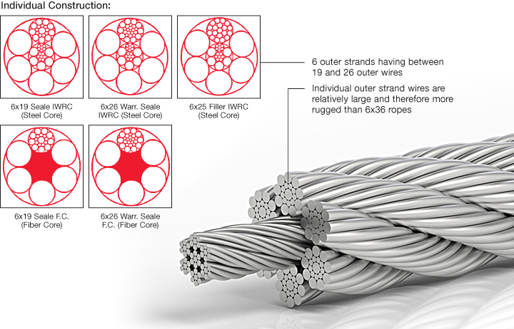
Breaking strength – The calculated breaking strength of a steel wire rope is defined as the metallic cross-section of a steel wire rope (the sum of the individual cross sections of all the wires making up the rope) multiplied by the nominal tensile strength of the steel wire rope. The minimum breaking strength of the steel wire rope is the calculated breaking strength of the rope multiplied by the spin factor. The actual breaking strength of a steel wire rope is the breaking strength of the rope as determined in a breaking test. A new steel wire rope is required to achieve an actual breaking strength equal to or higher than the minimum breaking strength.
The breaking strength of a steel wire rope can be increased by increasing the metallic area of the rope (e.g. by using strands with higher fill factors, by compacting the strands or by swaging the rope), by increasing the tensile strengths of the individual wires, or by increasing the spin factor of the rope. This can also be achieved by improving the contact conditions between the rope elements by using a plastic infill.
Bending fatigue resistance – The bending fatigue resistance of steel wire rope is defined as the number of bending cycles a rope can achieve in a bending fatigue test under defined parameters (e.g. running over sheaves with a defined diameter and a pre-determined line pull corresponding to the minimum braking load of the steel wire rope). The bending fatigue resistance of the steel wire rope increases with increasing D/d ratio (sheave diameter (D) / nominal rope diameter (d)), and by reducing the line pull.
The bending fatigue resistance of a steel wire rope can be increased by increasing the contact area between the steel wire rope and the sheave and by increasing the contact conditions between the rope elements, by adding a plastic layer between the IWRC, and the outer strands. Due to the larger contact area between the ropes and the sheaves and due to the increased flexibility, 8- strand wire ropes are more resistant to bending fatigue than 6- strand wire ropes of a similar design.
Flexibility – The flexibility of a wire rope is a measure of how easily the rope allows itself to bend around a given diameter. The flexibility of the wire rope is among other things dependent on the line pull. The flexibility of an unloaded rope can be measured by the sag of a rope under its own weight.
The flexibility of a steel wire rope typically increases with an increasing number of strands and wires in the rope. The flexibility is also influenced by the lay lengths of the strands, of the rope core and the rope, as well as by the gaps between wires and strands.
If a rope is not flexible enough, it is forced to bend around a sheave of a given diameter, which reduces the bending fatigue life of the rope. It also forced to bend around a drum of a given diameter. Spooling problems can be a consequence.
Efficiency factor – When running over a sheave, a wire rope has to be converted from a straight condition into a bent condition at the point when the rope runs onto the sheave and has to be converted again from the bent into the straight condition when it runs off the sheave. Also the bearing has to be turned. In doing so, the friction forces in the rope as well as the friction forces in the bearing have to be overcome. This leads to a change of the rope force.
One describes the relationship of the rope force on both sides of the sheave as the efficiency factor and accepts that this numerical value also takes into account the friction losses of the bearing. When measuring the efficiency factor of a wire rope, the loss of the line pull while the rope is running over the sheave is measured. An efficiency factor of 0.98, or alternatively a strength loss of 2 %, is normally assumed for wire ropes.
Wear resistance – Changes in line pull cause changes in the rope length. Rope sections lying on a sheave or on the first wraps of a drum can only adapt to the changing line pull by sliding over the groove surface of the sheave or the drum when the length change occurs. This relative motion causes abrasion (both in the grooves and on the special wire rope). Using less and hence larger outer wires can increase the wear resistance of the rope. The pressure between the sheave and the rope can be minimized due to the optimized contact areas and hence also the wear of the rope can be minimized. The wear resistance can also be influenced by the metallurgy of the outer strands.
Modulus of elasticity – The modulus of elasticity of a material is defined as the proportional factor between load and elongation. The modulus of elasticity is a material property. Besides the elastic properties of the wire material used, the modulus of elasticity of wire ropes is dependent on the rope geometry and the load history of the rope. Since this is not a material property, ISO 12076 recommends calling this factor as the ‘rope modulus’. Fig 4 shows the deformation behaviour of wire rope.
Fig 4(a) shows a load-elongation diagram of a wire. Here the modulus of elasticity can be determined as the gradient of the curve in the linear area. Fig 4(b) shows a load-elongation diagram of a strand. As the strand consists of several wires of different lengths and different lay lengths or different lay angles, here the shorter and less elastic elements get loaded first. For this reason the curve is not linear in the lower area. The graph only gets linear, when all the wires in the strand bear the load together.
Fig 4(c) shows the load-elongation diagram of a rope. Here also a non-linear correlation is found in the lower area between load and elongation. Here again the non-linearity can be explained by the overload of the shorter and the less elastic rope elements. The load-elongation diagram is linear in the area in which all elements share the load and plastically deform. As a result of settling effects, the modulus of elasticity of wire ropes increases over the life time. The biggest part of this change happens with the first loading of the rope. Later the modulus of elasticity varies only very slightly. For this reason a new wire rope is always to be loaded and relived multiple times before measuring the modulus of elasticity. The determination of the modulus of elasticity is described in ISO 12076.
Radial stability – The radial stability of a wire rope is a function of the rope geometry and the line pull. The radial stability of a steel wire rope typically reduces with an increasing number of rope elements. It also increases with the increase of the line pull. Ropes with insufficient radial stability are not suitable for multi-layer spooling.
Structural stability – It is necessary that a rope maintains its structure during its working life. Adding a plastic layer between the IWRC and the outer strands can increase the stability of the rope structure. The plastic fixes the position of the rope elements relative to each other.
Diameter reduction of a special wire rope – With increasing line pull, a special wire rope not only gets longer, but it also reduces in diameter. A great part of that diameter reduction is reversible which means that the rope diameter increases again after unloading. Part of the diameter reduction, however, is permanent. If the diameter reduction of a steel wire rope under load is too high, in multi-layer spooling the rope can pull into deeper layers of the drum. Hence, the diameter reduction of steel wire ropes is to be considered when designing ropes for multi-layer applications as shown in Fig 4(d).
Kinking – It results in the permanent rope deformation and localized wear. It is normally caused by allowing a loop to form in a slack line and then pulling the loop down to a tight permanent set.
Steel wire ropes are widely used in many applications such as crane, tower crane, surface and underground mining, excavation, logging of any type of terrain, tramway, elevator, oil and gas, drilling, marine and electrical constructions. They are used dynamically for lifting and hoisting in cranes and elevators, and for transmission of mechanical power. Wire rope is also used to transmit force in mechanisms, such as a Bowden cable or the control surfaces of an automobile or an airplane connected to levers and pedals. Wire ropes have to fulfill different requirements depending on where they are used. Some of the uses of the wire ropes are as follows.
Running ropes – They are also called stranded ropes. These wire ropes are bent over sheaves and drums. They are hence stressed mainly by bending and secondly by tension.
Stationary ropes – These ropes are stay ropes (spiral ropes, mostly full-locked) and have to carry tensile forces. These ropes are therefore mainly loaded by static and fluctuating tensile stresses. Ropes used for suspension are frequently called cable.
Track ropes – Track ropes (full locked ropes) have to act as rails for the rollers of cabins or other loads in aerial ropeways and cable cranes. In contrast to running ropes, track ropes do not take on the curvature of the rollers. Under the roller force, a so called free bending radius of the rope occurs. This radius increases (and the bending stresses decrease) with the tensile force and decreases with the roller force.
Wire rope slings – Wire (stranded ropes) are used to harness various kinds of goods. These slings are stressed by the tensile forces but first of all by bending stresses when bent over the more or less sharp edges of the goods.
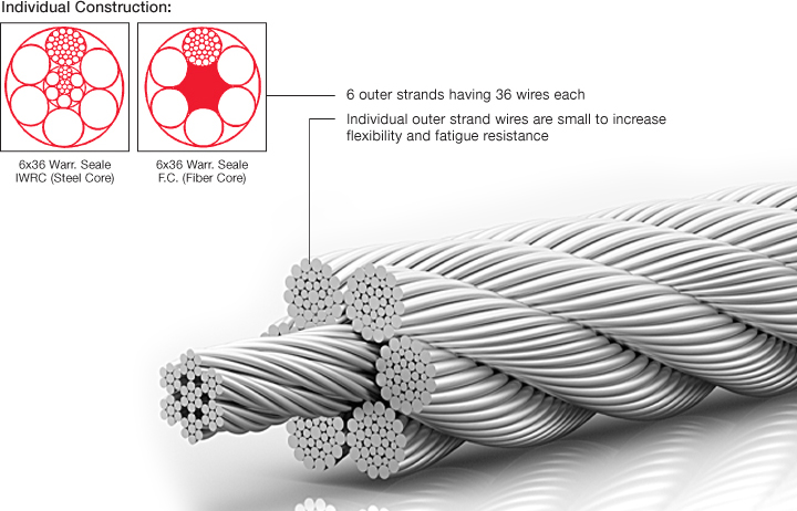
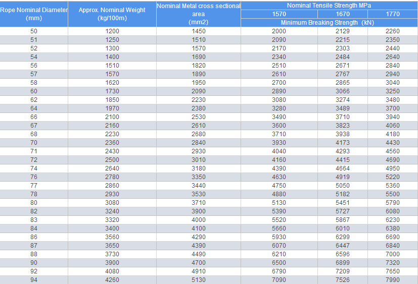
Galvanized wire rope is categorized by number of strands in its construction. We supply most of them but we concentrate on the two major categories of galvanized (and ungalvanized or bright) wire rope. These “classes” are referred to as 6x19 and 6x36. Within each category of galvanized wire rope there are different “constructions” illustrated in the tables below.
Wire rope, galvanized and ungalvanized is used for many kinds of projects and applications. No matter the application galvanized wire rope must be used properly to insure the safest working conditions. All of our galvanized wire rope is manufactured to meet or exceed Federal Specification RRW-410 and is mill certified.
All of these general purpose wire ropes are available in full reels, custom cut sizes or as part of a custom made wire rope sling. Contact us today for more information.
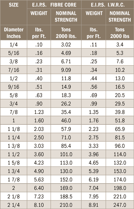
Galvanized wire rope also comes in different strength categories (IPS and EIPS) and different cores (FC or fiber core and IWRC or independent wire rope core). Relevant data for each is listed in the table below.
Wire rope classification is done by the number of strands as well as by the number of wires in each strand, e.g., 6 x 7, 6 x 19, 6 x 37, 8 x 19, 19 x 7, etc. However, these are nominal classifications that may or may not reflect the actual construction. For example, the 6 x 19 class includes constructions such as 6 x 21 filler wire, 6 x 25 filler wire, and 6 x 26 Warrington Seale. Despite the fact that none of the three constructions named have 19 wires, they are designated as being in the 6 x 19 classification.
Hence, a supplier receiving an order for 6 x 19 rope may assume this to be a class reference, and could possibly furnish any construction within this category. But, should the job require the special characteristics of a 6 x 25 filler wire, and a 6 x 19 Seale is supplied in its stead, a shorter service life may result.
To avoid such misunderstandings, the safest procedure is to order a specific construction. In the event that the specific construction is not known or is in doubt, the rope should be ordered by class along with a description of its end use.
Identification of wire rope in class groups facilitates selection on the basis of strength and weigh/foot since it is customary domestic industry practice that all ropes (from a given manufacturer) within a class have the same nominal strength and weigh/foot. As for other-functional-characteristics, these can be obtained by referencing the specific construction within the class.
Only three wire ropes under the 6 x 19 classification actually have 19 wires: 6 x 19 two-operation (2-op), 6 x 19 Seale (S), and 6 x 19 Warrington (W). All the rest have different wire counts. In the 6 x 37 class there is a greater variety of wire constructions. The commonly available constructions in the 6 x 37 class include: 6 x 31 Warrington Seale (WS), 6 x 36 WS, 6 x 41 Seale Filler Wire (SFW), 6 x 41 WS, 6 x 43 Filler Wire Seale (FWS), 6 x 46 WS, etc. – none of which contain exactly 37 wires.


 8613371530291