
nominal strength of wire rope brands
Wire rope is a complex mechanical device that has many moving parts all working in tandem to help support and move an object or load. In the lifting and rigging industries, wire rope is attached to a crane or hoist and fitted with swivels, shackles or hooks to attach to a load and move it in a controlled matter. It can also be used to lift and lower elevators, or as a means of support for suspension bridges or towers.
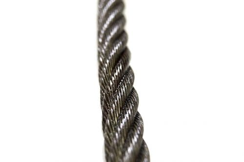
Wire rope is a preferred lifting device for many reasons. Its unique design consists of multiple steel wires that form individual strands laid in a helical pattern around a core. This structure provides strength, flexibility, and the ability to handle bending stresses. Different configurations of the material, wire, and strand structure will provide different benefits for the specific lifting application, including:Strength
However, selecting the proper wire rope for your lifting application requires some careful thought. Our goal is to help you understand the components of a wire rope, the construction of wire rope, and the different types of wire rope and what they might be used for. This will allow you to select the best performing and longest-lasting wire rope for the job at hand.
From childhood, many of us have been conditioned to think of a machine as some device with gears, shafts, belts, cams, and assorted whirring parts. Yet, by the rules of physics, an ordinary pry bar is a simple machine, even though it has only one part.
A wire rope is, in reality, a very complicated machine. A typical 6 x 25 rope has 150 wires in its outer strands, all of which move independently and together in a very complicated pattern around the core as the rope bends. Clearances between wires and strands are balanced when a rope is designed so that proper bearing clearances will exist to permit internal movement and adjustment of wires and strands when the rope has to bend. These clearances will vary as bending occurs, but are of the same range as the clearances found in automobile engine bearings.
Understanding and accepting the “machine idea” gives a rope user a greater respect for rope, and enables them to obtain better performance and longer useful life from rope applications. Anyone who uses a rope can use it more efficiently and effectively when they fully understand the machine concept.
Wires are the smallest component of wire rope and they make up the individual strands in the rope. Wires can be made from a variety of metal materials including steel, iron, stainless steel, monel, and bronze. The wires can be manufactured in a variety of grades that relate to the strength, resistance to wear, fatigue resistance, corrosion resistance, and curve of the wire rope.
Strands of wire rope consist of two or more wires arranged and twisted in a specific arrangement. The individual strands are then laid in a helical pattern around the core of the rope.
The core of a wire rope runs through the center of the rope and supports the strands and helps to maintain their relative position under loading and bending stresses. Cores can be made from a number of different materials including natural or synthetic fibers and steel.
Lubrication is applied during the manufacturing process and penetrates all the way to the core. Wire rope lubrication has two primary benefits:Reduces friction as the individual wires and strands move over each other
The number of layers of wires, the number of wires per layer, and the size of the wires per layer all affect the strand pattern type. Wire rope can be constructed using one of the following patterns, or can be constructed using two or more of the patterns below.Single Layer – The most common example is a 7 wire strand with a single-wire center and six wires of the same diameter around it.
Filler Wire – Two layers of uniform-size wire around a center with the inner layer having half the number of wires as the outer layer. Small filler wires, equal to the number in the inner layer, are laid in valleys of the inner wire.
Seale – Two layers of wires around a center with the same number of wires in each layer. All wires in each layer are the same diameter. The large outer wires rest in the valleys between the smaller inner wires.
Warrington – Two layers of wires around a center with one diameter of wire in the inner layer, and two diameters of wire alternating large and small in the outer later. The larger outer-layer wires rest in the valleys, and the smaller ones on the crowns of the inner layer.
On a preformed wire rope, the strands and wires are formed during the manufacturing process to the helical shape that they will take in a finished wire rope.
Preformed rope can be advantageous in certain applications where it needs to spool more uniformly on a drum, needs greater flexibility, or requires more fatigue-resistance when bending.
Direction and type of lay refer to the way the wires are laid to form a strand (either right or left) and how the strands are laid around the core (regular lay, lang lay, or alternate lay).Regular Lay – The wires line up with the axis of the rope. The direction of the wire lay in the strand is opposite to the direction of the strand lay. Regular lay ropes are more resistant to crushing forces, are more naturally rotation-resistant, and also spool better in a drum than lang lay ropes.
Lang Lay– The wires form an angle with the axis of the rope. The wire lay and strand lay around the core in the same direction. Lang Lay ropes have a greater fatigue-resistance and are more resistant to abrasion.
A fiber core can be made of natural or synthetic polypropylene fibers. Fiber cores offer greater elasticity than a steel core but are more susceptible to crushing and not recommended for high heat environments.
A steel core can be an independent wire rope or an individual strand. Steel cores are best suited for applications where a fiber core may not provide adequate support, or in an operating environment where temperatures could exceed 180° F.
The classifications of wire rope provide the total number of strands, as well as a nominal or exact number of wires in each strand. These are general classifications and may or may not reflect the actual construction of the strands. However, all wire ropes of the same size and wire grade in each classification will have the SAME strength and weight ratings and usually the same pricing.
Besides the general classifications of wire rope, there are other types of wire rope that are special construction and designed for special lifting applications.
Some types of wire rope, especially lang lay wire rope, are more susceptible to rotation when under load. Rotation resistant wire rope is designed to resist twisting, spinning, or rotating and can be used in a single line or multi-part system.
Special care must be taken when handling, unreeling, and installing rotation resistant wire rope. Improper handling or spooling can introduce twist into the rope which can cause uncontrolled rotation.
Compacted strand wire rope is manufactured using strands that have been compacted, reducing the outer diameter of the entire strand, by means of passing through a die or rollers. This process occurs prior to closing of the rope.
This process flattens the surface of the outer wires in the strand, but also increases the density of the strand. This results in a smoother outer surface and increases the strength compared to comparable round wire rope (comparing same diameter and classification), while also helping to extend the surface life due to increased wear resistance.
A swaged wire rope differs from a compacted strand wire rope, in that a swaged wire rope’s diameter is compacted, or reduced, by a rotary swager machine after the wire rope has been closed. A swaged wire rope can be manufactured using round or compacted strands.
The advantages of a swaged wire rope are that they are more resistant to wear, have better crushing resistance, and high strength compared to a round strand wire rope of equal diameter and classification. However, a swaged wire rope may have less bending fatigue resistance.
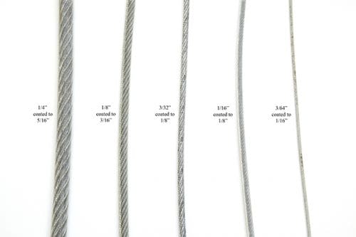
A plastic coating can be applied to the exterior surface of a wire rope to provide protection against abrasion, wear, and other environmental factors that may cause corrosion. However, because you can’t see the individual strands and wires underneath the plastic coating, they can be difficult to inspect.
Plastic filled wire ropes are impregnated with a matrix of plastic where the internal spaces between the strands and wires are filled. Plastic filling helps to improve bending fatigue by reducing the wear internally and externally. Plastic filled wire ropes are used for demanding lifting applications.
This type of wire rope uses an Independent Wire Rope Core (IWRC) that is either filled with plastic or coated in plastic to reduce internal wear and increase bending fatigue life.
Remember, wire rope is a complex piece of mechanical machinery. There are a number of different specifications and properties that can affect the performance and service life of wire rope. Consider the following when specifying the best type of wire rope for your lifting application:Strength
When you select a piece of rope that is resistant to one property, you will most likely have a trade-off that affects another property. For example, a fiber core rope will be more flexible, but may have less crushing resistance. A rope with larger diameter wires will be more abrasion resistant, but will offer less fatigue resistance.
At Mazzella Companies, we offer all different kinds of wire rope from all of the leading manufacturers. We sell the highest-quality domestic and non-domestic rigging products because product quality and operating safety go hand-in-hand. We have one of the largest and most complete inventories of both domestic and non-domestic rigging and lifting products to suit your lifting needs.
If you’re looking for a standard or custom specified wire rope for your lifting project, contact a Lifting Specialist at a Mazzella Companies location near you.
We stock well over 2,000,000 feet of wire rope in our various locations … ready for immediate delivery! We provide wire rope assemblies, and manufacture bridge cables, crane cables, steel mill cables, and thousands of OEM assemblies.
The 6 x 19 classification of wire ropes includes standard 6 strand, round strand ropes with 16 through 26 wires per strand. The 6 x 36 classification of wire ropes includes standard 6 strand, round strand ropes with 27 through 49 wires per strand. Although their operating characteristics vary, all have the same weight per foot and the same nominal strength, size for size.
While the 6 x 19 ropes give primary emphasis to abrasion resistance in varying degrees, the 6 x 36 ropes are important for their fatigue resistance. This fatigue resistance is made possible by the greater number of small wires per strand.
Although there are exceptions for special applications, the constructions in 6 x 36 classification are primarily designed to be the most efficient for each rope diameter. As the rope size increases, for instance, a large number of wires can be used to achieve required fatigue resistance, and still those wires will be large enough to offer adequate resistance to abrasion.
In this construction, each strand has nine outer wires over nine smaller inner wires over one large center wire. A comparison of cross-sections shows that these outside wires are larger than those of the 6 x 25FW or 6 x 26WS. Therefore, its resistance to abrasion is increased, but its fatigue resistance is decreased. This is a good rope to withstand abrasion or crushing on the drum.
To most wire rope users, 6 x 19 means 6 x 25 filler wire. It is the most common rope in the 6 x 19 classification. This rope has a good balance between both abrasion resistance and fatigue resistance in relation to other ropes.
This construction has better resistance to abrasion than a 6 x 25FW. It also features a compact construction with solid support for the wires; hence, it has a high resistance to crushing. Its number and relative size of the inner wires add to the stability of the strand and gives it a fatigue resistance comparable to a 6 x 25FW.
A standard 6 x 26WS construction provides the best rope for a wide range of applications. In general, we recommend the use of a 6 x 26WS in any application where a 6 x 25FW is used.
In most rope sizes, only one 6 x 36 classification rope is made. These constructions were selected to provide fatigue resistance without having wires that are too small.
The greater number of wires in the 6 x 36 classification makes these ropes more susceptible to crushing. This can be minimized, however, by specifying an Independent Wire Rope Core (IWRC) and by using well-designed sheaves, grooved drums and proper operating techniques.
Rotation-resistant ropes can frequently provide the best and most economical service in specific applications when you choose, handle and use them properly.
Contra-helically laid, rotation-resistant ropes are different from standard ropes because they"re designed to reduce rope torque. Modes of failure and wear for rotation-resistant ropes can differ from those for standard rope constructions. The very nature of these ropes requires special handling, selection and usage not encountered with standard constructions. They are susceptible to kinking, crushing and unbalancing in the form of "core pops" and "birdcages" Use extreme care to avoid operational practices that can possibly lead to these conditions.
Rotation-resistant ropes should not be used with swivels that allow rope rotation -- or in single part lifts where the load can rotate. Rotation will cause a reduction in strength, unequal loading in the rope and possible rope unbalance. If any significant change in diameter is found in a short length of a rotation-resistant rope, the rope needs to be replaced.
These ropes should be replaced when you see two randomly distributed crown wire breaks in six rope diameters -- or four randomly distributed crown wire breaks in 30 rope diameters.
Because rotation-resistant ropes are special, there are separate design, maintenance, inspection and removal criteria established for them by applicable industry regulations and standards.
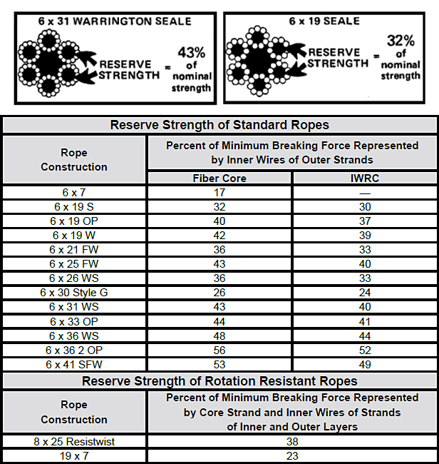
In an application where a single-part hoist rope is used to lift a free load -- or where rotation-resistant properties are essential for rope performance -- the 19 x 7 can be used. Its rotation-resistant characteristic is achieved by laying six strands around a core strand in one direction, then laying 12 strands around the first operation in the opposite direction. Thus, when the rope is in tension, opposing rotational forces are created between the inner and outer layers.
In addition, frequent and regular inspection for broken wires is critical when using this rope. Due to its design, the 19 x 7 construction has a relatively low reserve strength. This can result in short service life between the point in time when the broken wire removal criteria are met and when actual rope failure occurs.
In a multi-part wire rope system where the blocks have a tendency to twist -- or for a single-part hoist line that doesn"t require the degree of rotation-resistant properties found in a 19 x 7 rope -- the 8 x 25 Resistwist rope has found successful application. The rotation-resistant characteristic is achieved by laying the eight outer strands around an independent wire rope core so these strands are in the opposite direction to the lay of the core. Thus, when the rope is in tension, opposing rotational forces are created between the core and the outer strands.
Though not as rotation-resistant, the 8 x 25 Rotation Resistant rope is more stable than a 19 x 7 rope. It also has increased resistance to bending fatigue and crushing. This is achieved through the use of eight-strand construction with an independent wire rope core.
Like any application where an installation"s rope type is changed, the 8 x 25 Rotation Resistant rope should be substituted only after carefully comparing specifications and strength requirements.
Some of our calculators and applications let you save application data to your local computer. These applications will - due to browser restrictions - send data between your browser and our server. We don"t save this data.
Wire rope classification is done by the number of strands as well as by the number of wires in each strand, e.g., 6 x 7, 6 x 19, 6 x 37, 8 x 19, 19 x 7, etc. However, these are nominal classifications that may or may not reflect the actual construction. For example, the 6 x 19 class includes constructions such as 6 x 21 filler wire, 6 x 25 filler wire, and 6 x 26 Warrington Seale. Despite the fact that none of the three constructions named have 19 wires, they are designated as being in the 6 x 19 classification.
Hence, a supplier receiving an order for 6 x 19 rope may assume this to be a class reference, and could possibly furnish any construction within this category. But, should the job require the special characteristics of a 6 x 25 filler wire, and a 6 x 19 Seale is supplied in its stead, a shorter service life may result.
To avoid such misunderstandings, the safest procedure is to order a specific construction. In the event that the specific construction is not known or is in doubt, the rope should be ordered by class along with a description of its end use.
Identification of wire rope in class groups facilitates selection on the basis of strength and weigh/foot since it is customary domestic industry practice that all ropes (from a given manufacturer) within a class have the same nominal strength and weigh/foot. As for other-functional-characteristics, these can be obtained by referencing the specific construction within the class.
Only three wire ropes under the 6 x 19 classification actually have 19 wires: 6 x 19 two-operation (2-op), 6 x 19 Seale (S), and 6 x 19 Warrington (W). All the rest have different wire counts. In the 6 x 37 class there is a greater variety of wire constructions. The commonly available constructions in the 6 x 37 class include: 6 x 31 Warrington Seale (WS), 6 x 36 WS, 6 x 41 Seale Filler Wire (SFW), 6 x 41 WS, 6 x 43 Filler Wire Seale (FWS), 6 x 46 WS, etc. – none of which contain exactly 37 wires.

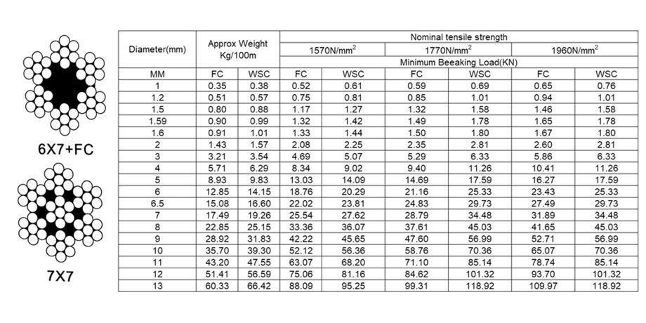
Wire rope strength is normally refered to as minimum breaking force or minimum breaking load. The minimum breaking load of any given rope diameter can be increased in two basic ways;
1. An increase in the tensile strength of the wire used to manufacture the rope will increase the minimum breaking load of the final rope. Typical tensile grades of wire used for crane rope manufacture are 1770N/mm2, 1960N/mm2 and 2160N/mm2.
2. Additionally it is possible to increase the steel fill factor of the wire rope. Fill factor means the ratio between the sum of the nominal cross sectional areas of all the wires in the rope and the circumscribed area of the rope based on its nominal diameter. More simply it measures the metallic cross sectional area of the rope.
It is possible to marginally increase the fill factor by varying the construction i.e. adding smaller filler wires. More effectively the individual strands of the rope can be compacted.
The resultant rope has a very high steel fill factor and consequently a relatively high minimum breaking load for any given diameter when compared with a conventional rope.
The high breaking load to diameter relationship offered by compacted ropes can allow crane manufacturers to optimise the design of crane components such as winding drums and sheaves whilst still complying with international crane design standards.
Lower stress levels which occur when crane operators replace a conventional rope with an identical diameter of high strength compacted rope can lead to more ‘comfortable’ operation and longer rope life. Diameter
Correct and consistent wire rope diameter is critical to performance on a modern crane, and a rope which is too large or too small, for the drum and sheaves in which it is operating can cause premature rope failure.
It is not only important to select a rope which has the correct nominal diameter according to the original equipment operating manual, but it is also important that the diameter of the rope is consistent throughout its entire length. Inconsistency in diameter, particularly short lengths where the rope is oversize, can cause premature localised wire breaks and short rope life.
Wire rope strength is normally refered to as minimum breaking force or minimum breaking load. The minimum breaking load of any given rope diameter can be increased in two basic ways;
Bend fatigue resistance is the ability of the wire rope to withstand repeated bending under constant or fluctuating loads. As the load increases in any reeving system so the rate of fatigue will increase. As bending radii decrease in a reeving system so the rate of fatigue will increase.
The compacted strand has very favourable internal and external contact conditions when compared with the point contact of round wires within a conventional strand.
The smooth surface of compacted rope offers a wider bearing surface to the sheave or drum groove. Increased fill factor, lowering internal stress levels, combined with improved internal and external contact conditions lead to longer rope life.
Laboratory fatigue testing indicates that it is possible to achieve up to two times normal rope life when comparing compacted rope with a conventional rope of equivalent construction.
Each wire rope construction will have an inherent torque characteristic where both ends of the rope are secured and an applied force will generate torque at the fixing points. Each wire rope construction will have an inherent turn characteristic where one end of the rope is free to rotate and an applied force will cause the free end of the rope to turn.
The torque or turn generated will depend upon the magnitude of the force applied and also upon the construction of the wire rope selected.In terms of resistance to rotation wire ropes can be divided into three basic catgories.
Single layer ropes have a much greater tendency to rotate under load than the two or three layer ropes which are often referred to as rotation resistant. Similarly the three layer rope will have less tendency to rotate when compared with the two layer rope.
Both the two layer and three layer ropes depend on torsional balance between the outer and inner layers to create rotational stability. With correct rope selection rotation should not cause a problem in service provided that the rope has been correctly balanced in design and manufacture.
Before selecting a rotation resistant rope, consideration should be given to a single layer construction. If the application/duty in question does not require the rope to resist rotation then it is possible that a single layer rope can represent a more robust and more effective solution.
Safety note – Single layer Langs lay ropes (where the direction of strand lay is the same as the direction of rope lay) have exceptionally bad rotational characteristics and must only be used in applications where both ends of the rope are securely fixed.
In multi-layer coiling situations where crushing of lower layers particularly at crossover point is unavoidable. Carl Stahl UK would recommend the use of compacted rope. The high steel fill factor, which is a feature of the compaction process, will offer greater resistance to crushing than an equivalent conventional rope.
Larger external wires can provide greater resistance to wear and abrasion therefore a 6×19 construction might be selected in preference to a 6×36 construction in a situation in which wear and abrasion rather than bend fatigue are the principle cause of rope deterioration.
The smooth surface of the compacted rope offers a wider bearing surface to the sheave or drum groove resulting in improved resistance to wear and abrasion.
Abrasive wear can occur between the rope and any ancillary equipment such as sheaves and the surface of the winding drum but probably the most significant cause of abrasive wear on cranes takes place between adjacent laps of rope where the rope moves on and off the winding drum.
Selection of a compacted rope with its smooth external surface and very good contact condition will minimise abrasive wear between the rope and ancillary equipment and also between adjacent laps of rope.
Laboratory bend fatigue tests show the significant effect which high performance manufacturing lubricant and in-service lubrication has on rope life. In-service lubrication with a suitable lubricant should be carried out wherever possible however the best opportunity to introduce lubricant into the rope is during manufacture.

Rope strength is a misunderstood metric. One boater will talk about tensile strength, while the other will talk about working load. Both of these are important measurements, and it’s worth learning how to measure and understand them. Each of these measurements has different uses, and here we’re going to give a brief overview of what’s what. Here’s all you need to know about rope strength.
Each type of line, natural fiber, synthetic and wire rope, have different breaking strengths and safe working loads. Natural breaking strength of manila line is the standard against which other lines are compared. Synthetic lines have been assigned “comparison factors” against which they are compared to manila line. The basic breaking strength factor for manila line is found by multiplying the square of the circumference of the line by 900 lbs.
When you purchase line you will buy it by its diameter. However, for purposes of the USCG license exams, all lines must be measured by circumference. To convert use the following formula.
As an example, if you had a piece of ½” manila line and wanted to find the breaking strength, you would first calculate the circumference. (.5 X 3.14 = 1.57) Then using the formula above:
To calculate the breaking strength of synthetic lines you need to add one more factor. As mentioned above, a comparison factor has been developed to compare the breaking strength of synthetics over manila. Since synthetics are stronger than manila an additional multiplication step is added to the formula above.
Using the example above, letÂ’s find the breaking strength of a piece of ½” nylon line. First, convert the diameter to the circumference as we did above and then write the formula including the extra comparison factor step.
Knots and splices will reduce the breaking strength of a line by as much as 50 to 60 percent. The weakest point in the line is the knot or slice. However, a splice is stronger than a knot.
Just being able to calculate breaking strength doesn’t give one a safety margin. The breaking strength formula was developed on the average breaking strength of a new line under laboratory conditions. Without straining the line until it parts, you don’t know if that particular piece of line was above average or below average. For more information, we have discussed the safe working load of ropes made of different materials in this article here.
It’s very important to understand the fundamental differences between the tensile strength of a rope, and a rope’s working load. Both terms refer to rope strength but they’re not the same measurement.
A rope’s tensile strength is the measure of a brand-new rope’s breaking point tested under strict laboratory-controlled conditions. These tests are done by incrementally increasing the load that a rope is expected to carry, until the rope breaks. Rather than adding weight to a line, the test is performed by wrapping the rope around two capstans that slowly turn the rope, adding increasing tension until the rope fails. This test will be repeated on numerous ropes, and an average will be taken. Note that all of these tests will use the ASTM test method D-6268.
The average number will be quoted as the rope’s tensile strength. However, a manufacturer may also test a rope’s minimum tensile strength. This number is often used instead. A rope’s minimum tensile strength is calculated in the same way, but it takes the average strength rating and reduces it by 20%.
A rope’s working load is a different measurement altogether. It’s determined by taking the tensile strength rating and dividing it accordingly, making a figure that’s more in-line with an appropriate maximum load, taking factors such as construction, weave, and rope longevity into the mix as well. A large number of variables will determine the maximum working load of a rope, including the age and condition of the rope too. It’s a complicated equation (as demonstrated above) and if math isn’t your strong point, it’s best left to professionals.
However, if you want to make an educated guess at the recommended working load of a rope, it usually falls between 15% and 25% of the line’s tensile strength rating. It’s a lotlower than you’d think. There are some exceptions, and different construction methods yield different results. For example, a Nylon rope braided with certain fibers may have a stronger working load than a rope twisted out of natural fibers.
For safety purposes, always refer to the information issued by your rope’s manufacturer, and pay close attention to the working load and don’t exceed it. Safety first! Always.
If you’re a regular sailor, climber, or arborist, or just have a keen interest in knot-tying, be warned! Every knot that you tie will reduce your rope’s overall tensile strength. Some knots aren’t particularly damaging, while others can be devastating. A good rule of thumb is to accept the fact that a tied knot will reduce your rope’s tensile strength by around 50%. That’s an extreme figure, sure, but when it comes to hauling critical loads, why take chances?
Knots are unavoidable: they’re useful, practical, and strong. Splices are the same. They both degrade a rope’s strength. They do this because a slight distortion of a rope will cause certain parts of the rope (namely the outer strands) to carry more weight than others (the inner strand). In some cases, the outer strands end up carrying all the weight while the inner strands carry none of it! This isn’t ideal, as you can imagine.
Some knots cause certain fibers to become compressed, and others stretched. When combined together, all of these issues can have a substantial effect on a rope’s ability to carry loads.
Naturally, it’s not always as drastic as strength loss of 50% or more. Some knots aren’t that damaging, some loads aren’t significant enough to cause stress, and some rope materials, such as polypropylene, Dyneema, and other modern fibers, are more resilient than others. Just keep in mind that any knots or splices will reduce your rope’s operations life span. And that’s before we talk about other factors such as the weather or your rope care regime…
6x36 is a flexible general engineering wire rope readily available in galvanised, ungalvanised and marine grade stainless steel. The wire rope has an equal lay construction (warrington seale) and achieves a superior breaking load to the 6x19 construction range. The construction has been designed to give a flexible rope with a good fatigue life. A 6x36 wire rope is available with either FC (fibre core) or IWRC (independent wire rope core) and is used for a wide range of applications, examples of which are shown below:
MAX Groups Marine is one of the most trusted suppliers of stainless steel and galvanised wire ropes/cables. Wire ropes consist of several strands of metal wire twisted into a helix form, forming extremely durable wire ropes for various marine purposes. Wire ropes are exposed to high fluctuation of contradicting forces, wear and tear or even corrosion in some cases. Thus, the quality of wire rope has to be taken very seriously.
Constant eye inspection and tests should be carried out to make sure the wire ropes are performing as they should. In MAX, all manufacturing of wire ropes are supervised and tested by professional technicians at all times.
Commonly used types of wire ropes may be of a fiber core (FC), Wire Strand core (WSC) or an Independent Wire Rope Core (IWRC). Usually IWRC core ropes are more durable whereas fibre core wire ropes are more elastic. The choice of wire rope core mostly depends on the usage and situation.
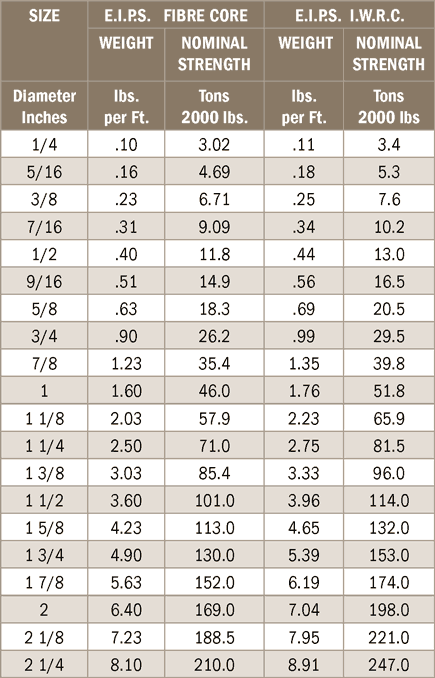
Most wire ropes are made from high-carbon steel, iron, stainless steel, bronze and more. Carbon steel wire ropes are graded from IPS (Improved Plow Steel), EIPS (Extra Improved Plow Steel to EEIPS (Extra Extra Improved Plow Steel), with each grade signifying its nominal strength. The most popular MAX steel wire ropes are of EIPS grade.
It doesn’t matter whether the lay direction is right (Z) or left (S), ordinary lay or langlay, MAX wire ropes are designed to have high durability and tensile strength for heavy industry usage.
For wire rope slings, you may opt for thimble eye (where a thimble if fixed inside the loop to preserve the natural loop shape and prevent direct contact that will damage the cable) or soft eye. Besides, rope ends with machine swaged with ferrules or sockets is a better option than hand spliced slings as it offers more protection.
Do you experience a short lifespan for your steel wire ropes? Deal with a supplier who is slow in responding & customer service? Or did you pay high prices for average quality products that fails you all the time? 83% of our clients claim that these made them search for a better option and subsequently worked with us since.
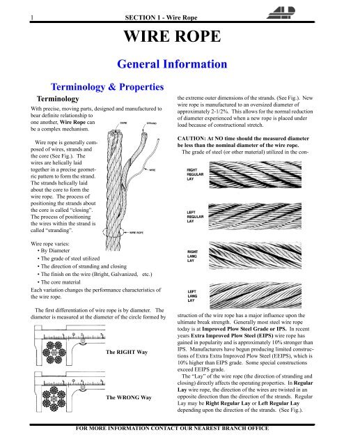
Wire rope is manufactured with dozens–even hundreds– of individual wires which are formed and fabricated to move or operate at close tolerances to one another. When a wire rope bends, each of its many wires slide and adjust to accommodate the differences in length between the inside and outside of the bend. The sharper the bend, the greater the movement. Every wire has three basic components: wires, strands and core. The core may be either fiber (FC) such as sisal, manila, jute, or an Independent Wire Rope Core (IWRC), which is actually a smaller wire rope within the strands of the outer wire rope. The wires are predominantly constructed from high-carbon steel, but may also be formed from various metals such as iron, stainless steel, monel or bronze. Carbon steel wire rope is manufactured in various grades, including Improved Plow Steel (IPS), Extra Improved Plow Steel (EIPS) and Extra Extra Improved Plow Steel (EEIPS), which designate the nominal strength of the wire rope. EIPS is the most commonly used and manufactured grade today.


 8613371530291