
non rotation vs rotation resistant wire rope supplier
Rope Services Direct supplies a variety of anti-spin non rotating wire rope (also called rotation resistant wire-rope). All standard rope wirehas a tendency to develop torque and therefore prone to rotation, whereas non-rotating wire ropes are designed so that the wire-rope outer rotational force naturally counteracts the inner strands rotational force. This is in the event that a rope is subjected to a load.
Rope elongation and rotation occurs on standard ropes when loaded, which can therefore spin the load, quite possibly out of control, which can be dangerous. When the rope rotates in this way the strands will begin to unravel. This causes the rope to lose strength and will undoubtedly fail, which could be catastrophic. It is for these reasons that non rotating wire rope is commonly used for many types of lifting applications including main hoist rope, whip rope,crane rope, off-shore and deck rope and more.
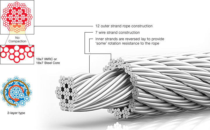
Non rotating wire rope or rotation resistant wire rope has a different construction to standard. as wires and strands are not laid in the same direction like they would be on standard rope. Inner and outer strands of wires are laid in opposite directions. For example the inner may be constructed in left hand lay whilst the outer layer is in right hand lay. The nature of this construction means that torsional forces on the inner and outer wires/strands will counteract each other and therefore minimising the risk of unraveling.
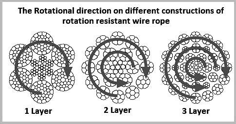
It is worth noting that the number of strand layers will have an effect of the resistance of rotation. A 2 layer rope has less resistance than a 3 layer rope. Therefore the more layers the rope has the greater rotation resistance it will have.
These types of ropes can be classified as spin resistant, rotation resistant or non rotation resistant. Classed on the basis of the number of rotations a certain length of rope does when a force of 20% of the MBF is applied; with 1 turn or less the rope will be classified as non rotating; with rotations between 1 & 4 the rope is classed as low rotation and for rotations between 4 & 10 the rope will be classified as spin resistant, any higher and the rope is NOT rotation resistant at all.
Correct usage and care with handling will prolong the working life. This is due to the friction on the inner wires caused by the strand crossover’s which will eventually cause the inner wires to break up. This is more apparent on non rotating wire rope with two layers. Ropes with 3 or more strand layers will distribute the radial pressures more evenly. Which will reduce friction and stress on the inner wires.
Regular,thorough inspectionsof non rotating rope are essential due to the fact that it is the inner strands that often break first and broken internal wires often go unnoticed as they are difficult to see.Rope Services Direct offer inspectionson all rope with certification issued on completion.
Holding both ends of the rope will prevent unraveling. Correctly fitted terminations will help to prevent damage. Kinking and unraveling may occur and they can also have an effect on the rotational balance if not fitted correctly.
Rotation resistant wire rope refers to a series of steel ropes which minimizes the tendency to spin or rotation under load. These wire ropes boast special design - the outer layer is twisted in the reverse direction of inner layers for counteracting torsional forces generated from multi-layers of strands.
To achieve the resistance against the spin and rotation, all wire ropes are composed of at least two layers of strands. In general, more layers a rotation resistant wire rope has, more resistance it will boast. For example, 2-layer ropes is much easier to spin and rotate than 3-layer ones. Meanwhile, if one end of free rotation is allowed, 2-layer rope can only develop 55% to 75% of its breaking strength comparing with 95% to 100% of 3-layer ropes.
The 3-layer rope with more outer strands is capable to distribute more radial pressure onto inner layers and ideal for larger mobile such as all tower cranes.
Wire ropes with 8 to 10 strands & 2-layer constructions without reversely twisted inner strands have very similar appearance to rotation resistant wire ropes, but they are not.
Rotation resistant wire ropes are considered to be less stable needing to be handled and installed with great care. They must be taken to avoid high loads with small diameter sheaves.

The characteristic of these wire ropes are that the outer layer is twisted in the opposite direction of their inner layers. The sometimes confusing issue is that many 8-, 9- and 10 strand constructions are 2-layer types but their inner strands are NOT twisted in the opposite direction and therefore these rope are NOT spin-resistant; plus, for the untrained eye these ropes look very much alike their spin-resistant variants. These and regular 6-strand ropes will spin violently and unlay themselves when loaded when one rope end is allowed to spin freely. They may also develop a significant drop in breaking strength and an even larger drop in their fatigue life characteristic (Torsion Fatigue).
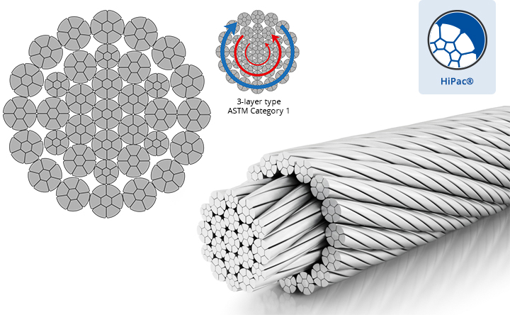
To achieve any degree of resisting the tendency of a rope to spin and unlay under load all such rope types (other than 4-strand ones) are constructed with 2 or more layers of opposite twisted strands (see picture on right).
2-layer ropes (MULTI, COMPAC 18) have a larger tendency to rotate than 3-layer ones (e.g. Class 34 x 7, COMPAC® 35). Furthermore, 2-layer spin-resistant and rotation resistant ropes will develop only about 55% to 75% of their breaking strength when one end is allowed to rotate freely. This number increases to between 95% to 100% for 3-layer (e.g. COMPAC® 35) non-rotating ropes.
Another important issue is that 2-layer rotation resistant and 2-layer spin-resistant rope types have shown to break up from the inside. The 8 (e.g. 8×25 spin-resistant) or 12 outer strands (19×7, 19×19, COMPAC®18) are not able to evenly distribute the radial forces and because of the inherent internal strand cross overs (which make the rope spin- or rotation resistant) the resultant severe notching stresses cause the rope core to break up premature (unless the core is plastic coated, e.g. Python® Multi). Unexpected and sudden rope failures may be the result. Moreover, 2-layer spin-resistant or rotation resistant ropes satisfy only low to moderate rotational resistance demands.
3-layer rope constructions (e.g. COMPAC® 35) have many more outer strands which can much better distribute the radial pressures onto the reverse lay inner strands. These ropes should be selected for larger mobile- and ALL tower cranes.
Rotation resistant wire rope is a special category (class) of wire rope designed to resist the tendency to spin or rotate under load. In general these ropes are used as single part lines, or in situations where operating conditions require a rope that will resist cabling in a multipart system. The essential nature of rotation resistant rope designs impose certain limitations on their application and necessitate special handling requirements not encountered with other rope constructions.
2) Multilayer strand (Multistrand)-consisting of two or more strand layers closed in opposing directions. Torsional forces generated by each layer of the rope counteract one another to minimize rotation.
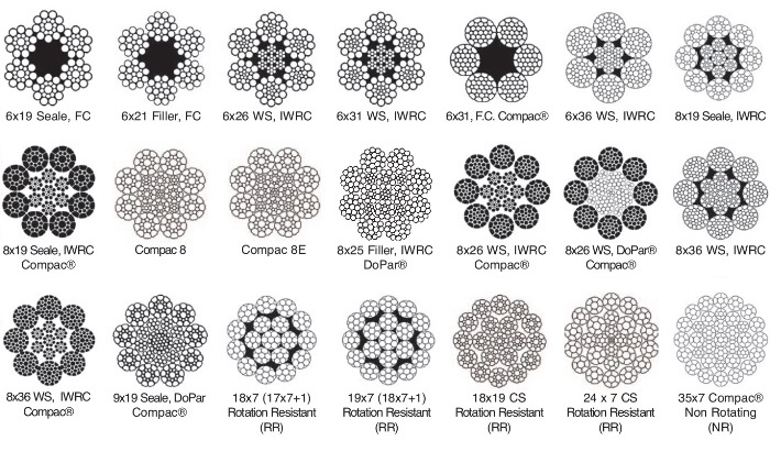
The multistrand classification includes ropes with between eight and twenty outer strands. Table 1 of this manual describes some of the more commonly available rotation resistant multistrand rope classification. In addition to these, a wide variety of special multistrand ropes is available. See (Figure 9). It would be impractical to cover the specific features of each in this manual.
In multistrand rotation resistant ropes the crossover points between strand layers are points of high stress concentration. Relative motion of the strands at these points results in accelerated deterioration of the internal components of the rope. Because of this design characteristic of the multistrand construction, care must be taken to avoid high loads with small diameter sheaves. Design factors less than five are not recommended.
The choice of the lay type must consider the specific use of the rope, the rope construction, crane components and the expected wear factors in use, which determine the lifetime of the rope substantially.
The aim of the rope choice is a high rope lifetime ensuring a high safety factor at the same time, which means the operator can recognize the secure operating condition of the rope reliably at any time, considering the discard criteria of the specific application. Therefore a general statement about the use of regular or lang’s lay ropes is not possible or not useful without knowledge of the specific case/application.
Ordinary lay ropes are widespread which are therefore presumably considered as universally applicable. Ordinary lay ropes have a very good structural stability due to the opposing stranding of the wires and strands which make them more resistant against external twist. The rope torque is lower than the one of lang’s lay ropes. Ordinary lay ropes also offer a good wear-resistance. Construction wise the externally visible wire breaks appear earlier of ordinary ropes than of lang’s lay ropes due to the higher pressure between wire and rope groove and a stronger wire bend within the strand, which makes it easier to recognize wire breaks and thus the rope state, making it easier to evaluate the discard criteria. Ordinary lay ropes are still no universal ropes for all applications under the abovementioned aims of the rope choice.
Lang’s lay ropes are more demanding not only in the production process, but also with the application, beginning with the installation. The reason for this lies in the stranding of wires and strands in the same direction, which raises the rope torque and makes lang’s lay ropes substantially more sensitively against every kind of external twist.
Lang’s lay ropes reach very high bending cycles until break because of the geometrically more favorable contact conditions between wire and rope groove which leads to the reduction of the pressure in the contact areas. This reduction of pressure is advantageous to the lifetime of the crane components and the rope itself.
However, it must also to be mentioned that in comparison to ordinary lay ropes the development of the externally visible wire breaks occurs more slowly. Therefore the recognition of the discard criteria due to externally visible wire breaks can be complvicated. For this reason the numbers of wire breaks until discard are clearly lower for lang’s lay ropes than for ordinary ropes with identical rope construction. Therefore also lang’s lay ropes are no universal ropes for all application under the abovementioned criteria of rope choice.
Important: As described in the “Lang’s Lay ropes” paragraph, these ropes can have an increased amount of internal wire breaks, which are not visible on the outside. This is expecially the case with rotation-resistant ropes in Lang Lay under bending cycle usage. This should always be clarified with a rope expert.
Besides the rope itself crane components and crane geometry are important criteria for the right rope choice. The applied drum system and the crane geometry constructively selected fleet angles are to mentioned particularly.
While on single-layer drums the rope gets stressed due to tensile load and substantially due to bend and lateral deflection and thus twists, dominates on multi-layer drums mechanical wear and lateral pressure stress between the touching ropes.
The crane geometry constructively selected fleet angle is a very important characteristic for a reliable rope spooling and the degree of rope wear. For multi-layer spooling a maximum fleet angle of 1,5° is recommended, while single-layer drums can work with higher fleet angels like for example up to 4°.
The following basic rules for the correct choice of rope lay types for ropes that spool on drums have proved themselves and therefore are also recommended by us:single-layer drums = ordinary lay ropes
On single-layer drums the ordinary lay ropes have clear advantages, because it can usually compensate the bigger fleet angle. Also the easier recognition of externally visible wire breaks is an important argument for the use of ordinary lay ropes on single-layer drums where strong mechanical rope wear, which also leads to wire breaks, does not or not substantially exist.
On multi-layer drums the bending fatigue resistance of the rope is not decisive for the rope lifetime but its resistance to mechanical impact is. Ordinary lay ropes are less suitable for multi-layer drum spooling because the wires of the neighboring ropes can rub with each other. This leads to high mechanical wear. The touch of the neighboring ropes during the spooling process is also well “audible”. The results are premature wire breaks. Lang’s lay ropes have proved themselves in the multi-layer spooling because neighboring ropes can not rub into each other, which raises the lifetime of the rope significantly.
The abovementioned statements have proved themselves in practice. Customer desired, occasionally divergences should therefore be analyzed thoroughly with regard to:specific operating conditions of the rope
SWR supply a large range of non-rotating wire ropes in both galvanised and ungalvanised finish with either ordinary or langs lay. Depending upon your requirement for higher breaking load or better wear characteristics, these wire ropes are available in different finishes and lubrications as well as being available with plastic impregnated.
This wire rope construction is available in both galvanised and ungalvanised finish with either ordinary or langs lay. The construction family includes 17X7, 18X7 and 19X7. For further flexibility and other performance characteristics we also supply 32X7, 35X7 and 37X7.
Depending upon your requirement for higher breaking load or better wear characteristics, these wire ropes are available in different finishes and lubrications as well as being available with plastic impregnated.
Original equipment wire rope and replacement wire rope must be selected and installed in accordance with the requirements of this section. Selection of replacement wire rope must be in accordance with the recommendations of the wire rope manufacturer, the equipment manufacturer, or a qualified person.
Wire rope design criteria: Wire rope (other than rotation resistant rope) must comply with either Option (1) or Option (2) of this section, as follows:
Option (1). Wire rope must comply with section 5-1.7.1 of ASME B30.5-2004 (incorporated by reference, see § 1926.6) except that section"s paragraph (c) must not apply.
Option (2). Wire rope must be designed to have, in relation to the equipment"s rated capacity, a sufficient minimum breaking force and design factor so that compliance with the applicable inspection provisions in § 1926.1413 will be an effective means of preventing sudden rope failure.
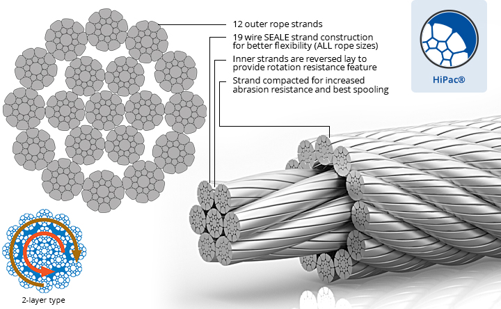
Type I rotation resistant wire rope ("Type I"). Type I rotation resistant rope is stranded rope constructed to have little or no tendency to rotate or, if guided, transmits little or no torque. It has at least 15 outer strands and comprises an assembly of at least three layers of strands laid helically over a center in two operations. The direction of lay of the outer strands is opposite to that of the underlying layer.
Type II rotation resistant wire rope ("Type II"). Type II rotation resistant rope is stranded rope constructed to have significant resistance to rotation. It has at least 10 outer strands and comprises an assembly of two or more layers of strands laid helically over a center in two or three operations. The direction of lay of the outer strands is opposite to that of the underlying layer.
Type III rotation resistant wire rope ("Type III"). Type III rotation resistant rope is stranded rope constructed to have limited resistance to rotation. It has no more than nine outer strands, and comprises an assembly of two layers of strands laid helically over a center in two operations. The direction of lay of the outer strands is opposite to that of the underlying layer.
Type I must have an operating design factor of no less than 5, except where the wire rope manufacturer and the equipment manufacturer approves the design factor, in writing.
When Types II and III with an operating design factor of less than 5 are used (for non-duty cycle, non-repetitive lifts), the following requirements must be met for each lifting operation:
A qualified person must inspect the rope in accordance with § 1926.1413(a). The rope must be used only if the qualified person determines that there are no deficiencies constituting a hazard. In making this determination, more than one broken wire in any one rope lay must be considered a hazard.
Each lift made under § 1926.1414(e)(3) must be recorded in the monthly and annual inspection documents. Such prior uses must be considered by the qualified person in determining whether to use the rope again.
Rotation resistant ropes may be used as boom hoist reeving when load hoists are used as boom hoists for attachments such as luffing attachments or boom and mast attachment systems. Under these conditions, all of the following requirements must be met:
The requirements in ASME B30.5-2004 sections 5-1.3.2(a), (a)(2) through (a)(4), (b) and (d) (incorporated by reference, see § 1926.6) except that the minimum pitch diameter for sheaves used in multiple rope reeving is 18 times the nominal diameter of the rope used (instead of the value of 16 specified in section 5-1.3.2(d)).
The operating design factor for these ropes must be the total minimum breaking force of all parts of rope in the system divided by the load imposed on the rope system when supporting the static weights of the structure and the load within the equipment"s rated capacity.
Wire rope clips used in conjunction with wedge sockets must be attached to the unloaded dead end of the rope only, except that the use of devices specifically designed for dead-ending rope in a wedge socket is permitted.
Prior to cutting a wire rope, seizings must be placed on each side of the point to be cut. The length and number of seizings must be in accordance with the wire rope manufacturer"s instructions.
The term “rotation resistant wire rope” refers to a type of wire rope that is designed to resist the inclination to spin or rotate under stress. These ropes are typically used as single-part lines or in instances where the operating requirements need a rope that can withstand cabling in a multipart system. The basic nature of rotation resistant rope designs places certain restrictions on their use and necessitates certain handling requirements not seen in other rope types.
Rotation resistant wire rope is designed to minimize load rotation during a lift. When lifting with other types of wire rope, elongation and rotation is normal. This can cause a load to spin, possibly out of control, which is a serious safety issue. Thus, rotation resistant wire rope is essential for any application where a load is lifted by a single line.
Rotation resistant wire rope is created by twisting the outer layer of the rope in the opposite direction to the inner layers of the rope. When under tension the opposing rotational forces cancel each other out.
2) Multilayer strand (Multistrand): two or more strand layers that are closed in opposite directions. Each layer of the rope generates torsional pressures that balance each other out, reducing rotation.
It’s important to remember that the amount of strand layers has an impact on rotational resistance. The resistance of a two-layer rope is lower than that of a three-layer rope. As a result, the more layers a rope has, the greater its rotation resistance.
Hercules SLR offers a wide selection of rotation resistant wire rope products and can custom fabricate rotation resistant wire rope products for specific requirements.
The inner core in rotation resistant wire rope can twist more tightly when a swivel is used. This significantly reduces rope strength and possibly causing early rope failure. Only during the initial installation phase, a swivel may be employed as a temporary device to help prevent any twisting of cabling caused by the installation process.
Once the rope installation is finished and the crane is operational, the swivel needs to be taken out of the reeving. With some rotation-resistant ropes, a swivel may be utilised; always check with the manufacturer.

In certain instances the use of rotation-resistant wire rope is necessary to provide rotational stability to the lifted load. In general, the use of these wire ropes is limited to those situations where it is impractical to:
Rotation-resistant wire ropes have less of a tendency to unlay when loaded than do conventional wire ropes. This results in improved rotational stability to the lifted load. Rotation-resistant wire ropes are designed in such a way that the rotational force of the outer strands is partially counteracted by the rotational force of the inner strands or core when the rope is subjected to a load.
The chart compares the rotational properties of rotation-resistant ropes with a standard 6x25 wire rope. The rotation-resistant ropes far surpass the rotational stability of a conventional 6x25 IWRC wire rope on both short and long falls.
ASME B30.5 specifies that rotation-resistant ropes have a safety design factor of five or greater. The required strength design factor of rotation-resistant rope becomes very important from the standpoint of maintaining the inherent low rotation of the rope and eliminating any tendency to overload the inner core, thereby causing a reduction in rope strength.
Precautions should be followed when using rotation-resistant wire rope. The rope ends must be properly seized and secured to prevent unlaying of the strands.
Due to the opposite lay direction of the inner core and outer strand layers in rotation-resistant ropes, care should be taken to avoid shock loading. Shock loading will result in distortion of the rope structure, causing bird-caging, core protrusion, etc. Due to the potential for complete rope failure, shock loaded wire ropes must be immediately removed from service.
Operation of 8x25, 19x7 and SPF 19 rotation-resistant wire ropes with a swivel is not recommended. The use of a swivel allows the inner core to twist tighter, resulting in a significant reduction in rope strength, possibly leading to premature rope failure. A swivel may be used as a temporary device only during the initial installation period to help eliminate any installation-induced twisting or cabling.
The swivel must be removed from the reeving after rope installation is completed and before the crane begins operation. A swivel may be used with some rotation resistant ropes, always confirm with the manufacturer.

Rotation resistant ropes are known to provide the best and most economical services for specific applications. When the correct ropes are selected and appropriately used, they are unmatched in the lifting market. Elephant hoists greatly benefit from rotation resistant wires.
Rotation resistance is created when wires are laid in a contra-helical position. These ropes are different from standard construction types because rotation resistant ropes are required to meet a different and higher set of service requirements. The modes of wear and failure for these ropes vary more than standard constructions. Special operational needs make specific limitations and special handling necessary. These are not encouraged with standard constructions.
Testing on ropes that are resistant to rotation commonly shows that the total length of service for these ropes is shorter than that of standard construction ropes. The tests show that there is a need for separate guidelines for the use, inspection, retirement, and application of resistant ropes.
Using a swivel at the load hook for rotation resistant ropes results in unpredictable service life. This type of practice can potentially lead to unbalanced loading between outer and inner layers of strands. This typically results in core failure. Any significant changes in diameter found in a small length of operating rope should be retired and replaced. Make sure to use appropriate rigging supplies for all crane wire rope applications.
For more information on the benefits of rotation resistant ropes, you should not hesitate to give our team a call. Do not forget to ask about our V rope options.
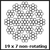
Widely used for hoisting unguided loads with a single part of rope. Typical applications are hoisting ropes on Derricks, boom cranes, shaft sinking hoists and freely suspended mine hoists. Both 19 X 7 and 8 X 19 are bright, right regular lay wire ropes.
Inner strands are left lang lay; outer strands are right regular lay; the natural rotation tendency of one layer is counter balanced by the other. Not recommended for multiple part lifting.
Inner and outer strands are laid in opposing directions to counter rotation. Although less rotation resistant, 8 X 19 has a higher strength factor. Acceptable for multiple part lifting.
/is2.ecplaza.com/ecplaza2/products/6/6d/6d5/2147026313/4415872.jpg)
Non-rotating wire ropes are designed so that the wire-rope outer rotational force naturally counteracts the inner strands rotational force in the event of a load applied.
Rather than all wires and strands being laid in the same direction, a rotation resistant wire rope consists of inner strands being laid in the opposite direction to the outer layers, for example the inner may be constructed in left hand lay whilst the outer layer is in right hand lay. This construction means that torsional forces on the inner and outer wires / strands will counteract each other and so minimise the risk of unraveling.
Using an ordinary lifting wire rope for a job or equipment which demand a non-rotating wire rope si very dangerous and it presents the following risks:

Rotation-resistant rope is defined as stranded rope designed to generate reduced levels of torque and rotation when loaded and comprised of two or more layers of strands laid helically around the center, with the direction of lay of the outers strands being opposite to that of the underlying layer. However, there are different levels of rotation resistance to consider.
Rotation-resistant rope (Category 1): Stranded rope constructed so that it displays little or no tendency to rotate, or, if guided, transmits little or no torque. It has at least 15 outer strands and is comprised of at least three layers of strands laid helically over a center in two operations, with the direction of lay of the outer strands being opposite to that of the underlying layer. This rope is also known as Non-Rotating.
Rotation-resistant rope (Category 2): Stranded rope constructed so that it has significant resistance to rotation. It has at least 10 outer strands and is comprised of two or more layers of strands laid helically over a center in two or three operations, with the direction of lay of the outer strands being opposite to that of the underlying layer. This rope is also known as Low Rotation.
Rotation-resistant rope (Category 3):Stranded rope constructed so that it has limited resistance to rotation. It has no more than 9 outer strands and is comprised of two layers of strands laid helically over a center in two operations, with the direction of lay of the outer strands being opposite to that of the underlying layer. This rope is also known as Spin Resistant.
Northern Strands Mining, Wire Rope, Attachments & Equipment Division excels by providing a wide range of equipment and services, by being the best full service provider of wire ropes, attachments, equipment and service. Truly Mine Hoisting Solutions®.
We stock a wide variety of rotation resistant wire ropes from several manufacturers.Some types of wire rope, especially lang lay wire rope, are more susceptible to rotation when under load. Rotation resistant wire rope is designed to resist twisting, spinning, or rotating and can be used in a single line or multi-part system.Special care must be taken when handling, unreeling, and installing rotation resistant wire rope. Improper handling or spooling can introduce twist into the rope which can cause uncontrolled rotation.Call us at 800.362.4601 or click here to get the rotation resistant wire rope you need!


 8613371530291