
osha wire rope guardrail supplier

This responds to your June 1, 1999, letter to the Occupational Safety and Health Administration (OSHA), requesting information on wire rope and Crosby clips used around the perimeter of buildings as a guardrail. You also requested clarification on when employees must tie-off when a guardrail system is removed to facilitate hoisting operations. We apologize for the long delay in providing this response.
Question 1: How many Crosby clips are required to be used when setting up a wire rope guardrail? Is it permissible to splice two wire ropes by overlapping or must the connections be turned back into eyelets and properly secured?
Answer: For construction work covered by 29 CFR 1926 Subpart M, §1926.502(b) sets forth the criteria that must be met when using wire rope as a guardrail. The standard requires guardrails to meet several specific criteria. For example, 1926.502(b)(3) states that the guardrail shall be capable of withstanding, without failure, a force of at least 200 pounds applied within 2 inches of the top edge, in any outward or downward direction, at any point along the top edge. Section 1926.502(b)(4) states that when the 200 pound test load noted in §1926.502(b)(3) is applied in a downward direction, the top edge of the guardrail shall not deflect to a height less than 39 inches above the walking/working level. Section 1926.502(b)(9) states that the top rail and mid-rails shall be at least ¼-inch nominal diameter or thickness to prevent cuts and lacerations. These and other criteria must be met when using wire rope as a guardrail around the perimeter of a building.
The OSHA standard does not specify a minimum number of clips when using wire rope as a guardrail. However, as a practical matter, it is unlikely you could meet the specific requirements under §1926.502(b) unless you follow the manufacturer"s recommendations for the number of clips to be used on wire ropes of different diameters (for example, the Crosby Group Inc. general catalog, 2000 edition has tables showing their recommendations for their clips). Also, note that OSHA"s standard for rigging equipment used for material handling, 29 CFR §1926.251, has a table for the number of clips required for wire rope ½-inch and greater. Although that standard does not apply to wire rope used for guardrails, when you design a rope system to meet the §1926.502 requirements, following those tables will normally ensure that you have enough clips.
Question 2: What are the requirements for tying-off employees when a guardrail system is removed to facilitate hoisting operations? 29 CFR §1926.501(b)(3) states that, when guardrails are removed to facilitate hoisting operations, employees who have to lean out over the edge must be tied off. What about other employees, who do not have to lean out—do they have to be tied-off also?
Answer: Section 1926.501(b)(3) states that each employee in a hoist area shall be protected from falls of 6 feet or more by guardrail systems or personal fall arrest systems. It also states that, "If guardrail systems ... are removed to facilitate the hoisting operation (e.g., during landing of materials), and an employee must lean through the access opening or out over the edge of the access opening (to receive or guide equipment and materials, for example), that employee shall be protected from fall hazards by a personal fall arrest system." (59 FR 40710).
You ask if this means that the only employees who must use fall protection when the guardrails are removed are those who must lean out. The answer is no; the first sentence of §1926.501(d)(3) requires that all employees in the hoist area be protected by either a guardrail or personal fall arrest system. So, when all or part of a guardrail has been removed, all employees must be protected by a personal fall arrest system.
If you need additional information, please contact us by fax at: U.S. Department of Labor, OSHA, Directorate of Construction, Office of Construction Standards and Guidance, fax # 202-693-1689. You can also contact us by mail at the above office, Room N3468, 200 Constitution Avenue, N.W., Washington, D.C. 20210, although there will be a delay in our receiving correspondence by mail.

This is in response to the questions posed in the letter from Jay Withrow regarding safety railing(s) required by OSHA Standard 29 CFR 1926.750(b)(1)(iii). The standard reads as follows:
"Floor periphery - safety railing. A safety railing of ½-inch wire rope or equal shall be installed, approximately 42 inches high, around the periphery of all temporary - planked or temporary metal-decked floors of tier buildings and other multifloored structures during structural steel assembly." (emphasis added).
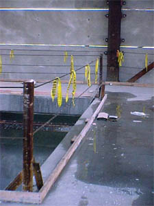
Question 1: Is orange plastic-coated 3/16-inch aircraft wire "equal" to ½-inch wire rope? (Note: This product is seeing extensive use in Northern Virginia).
Answer: The response is a qualified yes. The key to whether the 3/16 aircraft wire is equal to ½-inch wire rope is whether a the 3/16 aircraft wire is equal in strength to ½-inch wire rope.
The standard does not set forth any specifications for the design and construction of the ½-inch wire rope. Thus any wire rope ½-inch in diameter of any design or construction could be used to comply with this standard.
There is at least one 3/16-inch aircraft cable (Galvanized and tinned aircraft cord and strand Construction 1x19 - Nominal Breaking Strength 4700 pounds) that has a greater nominal breaking strength than does at least one type of ½-inch wire rope (Iron Galvanized Running Rope - Construction 6x12 - Nominal Breaking Strength 4560 pounds). Therefore, the previously referenced aircraft cable would have to be considered equal to ½-inch wire rope.
Question 3: Although it is not stated anywhere, must the wire rope used to comply with 1926.750(b)(1)(iii) (½-inch wire rope; or 3/16-inch aircraft wire if you find that to be equivalent) have a maximum permissible deflection of 3-inches in one direction when a load of 200 pounds is applied in any direction at any point?
Answer: The response to this question is a qualified yes. OSHA Standard 29 CFR 1926.750(b)(1)(iii) does not address the issue of deflection. The standard, as written, could be enforced so that no deflection is permitted. However that would be contrary to guidance relating to wire rope used for guardrails contained in directives (STD 3-10.3), memoranda and proposed standards (Fall Protection In Construction.)
Therefore in Region III, for the purpose of complying with OSHA Standard 29 CFR 1926.750(b)(1)(iii), a safety railing that meets the following criteria would be considered to be equal to a ½-inch wire rope:
[Correction 6/20/2005. See OSHA Directive CPL 02-01-034 "Inspection policy and procedures for OSHA"s steel erection standards for construction" published on 3/22/2002 for the current policy on OSHA"s steel erection standards (1926 Subpart R) for construction.]

Top edge height of top rails, or equivalent guardrail system members, shall be 42 inches (1.1 m) plus or minus 3 inches (8 cm) above the walking/working level. When conditions warrant, the height of the top edge may exceed the 45-inch height, provided the guardrail system meets all other criteria of this paragraph.
Midrails, screens, mesh, intermediate vertical members, or equivalent intermediate structural members shall be installed between the top edge of the guardrail system and the walking/working surface when there is no wall or parapet wall at least 21 inches (53 cm) high.
Other structural members (such as additional midrails and architectural panels) shall be installed such that there are no openings in the guardrail system that are more than 19 inches (.5 m) wide.
Guardrail systems shall be capable of withstanding, without failure, a force of at least 200 pounds (890 N) applied within 2 inches (5.1 cm) of the top edge, in any outward or downward direction, at any point along the top edge.
When the 200 pound (890 N) test load specified in paragraph (b)(3) of this section is applied in a downward direction, the top edge of the guardrail shall not deflect to a height less than 39 inches (1.0 m) above the walking/working level. Guardrail system components selected and constructed in accordance with the Appendix B to subpart M of this part will be deemed to meet this requirement.
Top rails and midrails shall be at least one-quarter inch (0.6 cm) nominal diameter or thickness to prevent cuts and lacerations. If wire rope is used for top rails, it shall be flagged at not more than 6-foot intervals with high-visibility material.
When guardrail systems are used at hoisting areas, a chain, gate or removable guardrail section shall be placed across the access opening between guardrail sections when hoisting operations are not taking place.
When guardrail systems are used around holes used for the passage of materials, the hole shall have not more than two sides provided with removable guardrail sections to allow the passage of materials. When the hole is not in use, it shall be closed over with a cover, or a guardrail system shall be provided along all unprotected sides or edges.
When guardrail systems are used around holes which are used as points of access (such as ladderways), they shall be provided with a gate, or be so offset that a person cannot walk directly into the hole.
Manila, plastic or synthetic rope being used for top rails or midrails shall be inspected as frequently as necessary to ensure that it continues to meet the strength requirements of paragraph (b)(3) of this section.
The maximum size of each safety net mesh opening shall not exceed 36 square inches (230 cm) nor be longer than 6 inches (15 cm) on any side, and the opening, measured center-to-center of mesh ropes or webbing, shall not be longer than 6 inches (15 cm). All mesh crossings shall be secured to prevent enlargement of the mesh opening.
During the construction of elevator shafts, two employees may be attached to the same lifeline in the hoistway, provided both employees are working atop a false car that is equipped with guardrails; the strength of the lifeline is 10,000 pounds [5,000 pounds per employee attached] (44.4 kN); and all other criteria specified in this paragraph for lifelines have been met.
Note: If the personal fall arrest system meets the criteria and protocols contained in Appendix C to subpart M, and if the system is being used by an employee having a combined person and tool weight of less than 310 pounds (140 kg), the system will be considered to be in compliance with the provisions of paragraph (d)(16) of this section. If the system is used by an employee having a combined tool and body weight of 310 pounds (140 kg) or more, then the employer must appropriately modify the criteria and protocols of the Appendix to provide proper protection for such heavier weights, or the system will not be deemed to be in compliance with the requirements of paragraph (d)(16) of this section.
Personal fall arrest systems shall not be attached to guardrail systems, nor shall they be attached to hoists except as specified in other subparts of this Part.
When the path to a point of access is not in use, a rope, wire, chain, or other barricade, equivalent in strength and height to the warning line, shall be placed across the path at the point where the path intersects the warning line erected around the work area, or the path shall be offset such that a person cannot walk directly into the work area.
The rope, wire, or chain shall be rigged and supported in such a way that its lowest point (including sag) is no less than 34 inches (.9 m) from the walking/working surface and its highest point is no more than 39 inches (1.0 m) from the walking/working surface;
After being erected, with the rope, wire, or chain attached, stanchions shall be capable of resisting, without tipping over, a force of at least 16 pounds (71 N) applied horizontally against the stanchion, 30 inches (.8 m) above the walking/working surface, perpendicular to the warning line, and in the direction of the floor, roof, or platform edge;
The rope, wire, or chain shall have a minimum tensile strength of 500 pounds (2.22 kN), and after being attached to the stanchions, shall be capable of supporting, without breaking, the loads applied to the stanchions as prescribed in paragraph (f)(2)(iii) of this section; and
Mechanical equipment on roofs shall be used or stored only in areas where employees are protected by a warning line system, guardrail system, or personal fall arrest system.
On floors and roofs where guardrail systems are not in place prior to the beginning of overhand bricklaying operations, controlled access zones shall be enlarged, as necessary, to enclose all points of access, material handling areas, and storage areas.
On floors and roofs where guardrail systems are in place, but need to be removed to allow overhand bricklaying work or leading edge work to take place, only that portion of the guardrail necessary to accomplish that day"s work shall be removed.
Where tools, equipment, or materials are piled higher than the top edge of a toeboard, paneling or screening shall be erected from the walking/working surface or toeboard to the top of a guardrail system"s top rail or midrail, for a distance sufficient to protect employees below.
The fall protection plan shall document the reasons why the use of conventional fall protection systems (guardrail systems, personal fall arrest systems, or safety nets systems) are infeasible or why their use would create a greater hazard.

This is in response to your letter of June 29, concerning the acceptability of wire rope and/or cable as a method of perimeter protection for a building under construction.
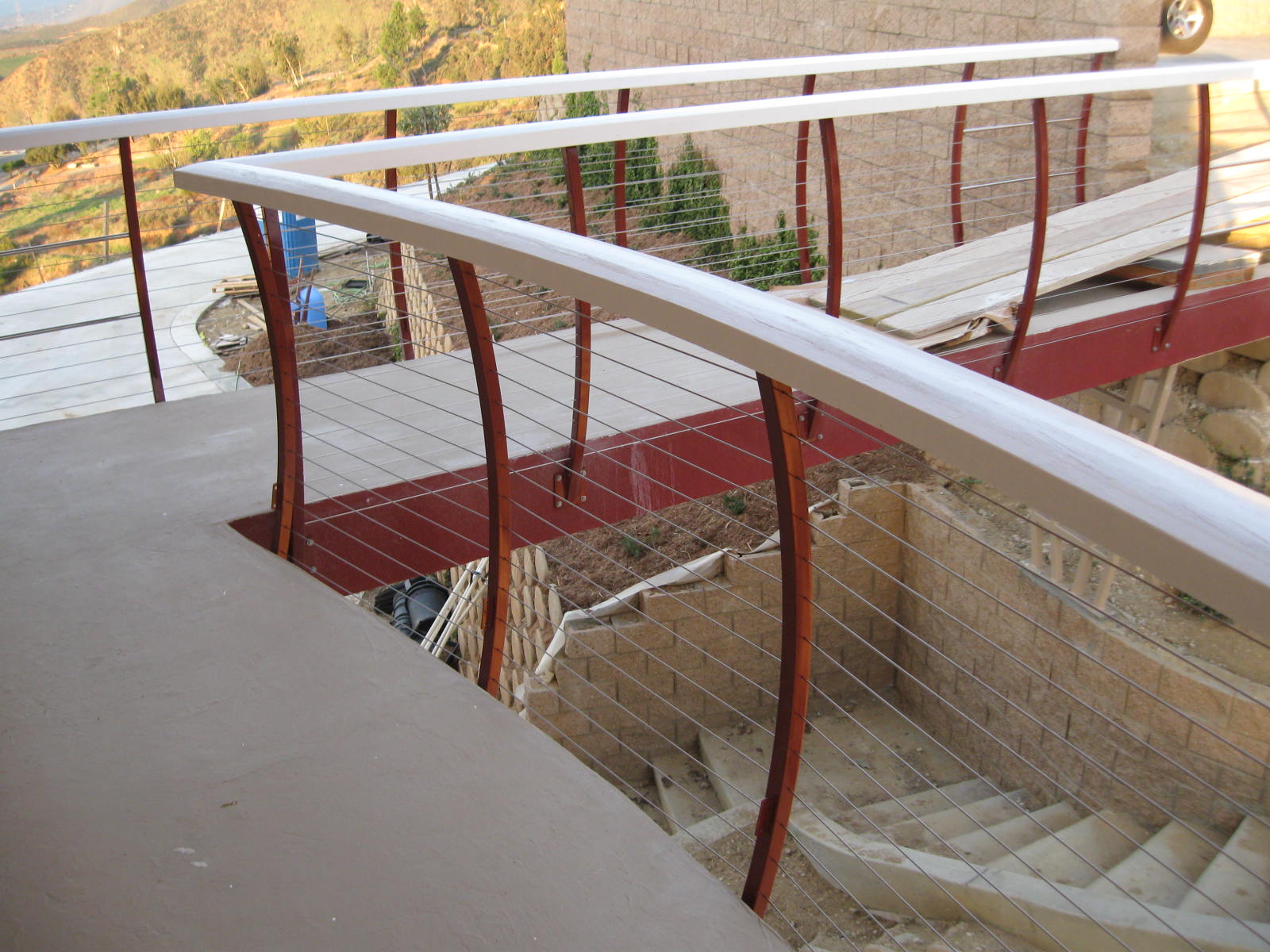
The use of wire ropes as top rails and intermediate rails of guardrail systems used for perimeter protection or for guardrails used on scaffolding meeting the equivalent requirements of 29 CFR 1926.500(d)(1) and 29 CFR 1926.451(a)(5) is acceptable provided it meets the following guidelines:
(3) The maximum deflection of the top rail when a load of 200 pounds is applied in any direction at any point on the top rail shall not exceed 3 inches in one direction which includes the free hanging sag in the wire rope.

Ontario’s Occupational Health and Safety Act, REGULATION 213/91 FOR CONSTRUCTION PROJECTS Section 26.3(5) (point load of 150 pounds applied to every 8 feet of guardrail at the top rail equivalent to 19 lb per linear foot)

The material must be durable, the top rail and the midrail must be at least 1/4 inch (.6 cm) in diameter. OSHA also requires the surface of the railing itself must be smooth to protect employees from injuries; such as cuts, punctures and to prevent snagging.
OSHA provides a range for the railings to ensure your system is safe and compliant. Guardrail height must be between 39 inches and 45 inches. The midrails should be placed halfway between the top edge of the railing and the working-walking surface.
The section of the OSHA code that specifies most of the primary guardrail requirements and directly relates to safety railing is 1910.29. Specifically, the following sections are the most relevant to railing and guardrail for fall protection.
OSHA deems any change in elevation of 48 inches or more to be a fall hazard requiring a form of fall protection in walking-working areas. Protection can range anywhere from company policy and warning signs to railings systems. It’s important to contact an expert to fully understand what you need or might not need.
OSHA states that guardrail must reach a height of 42 inches, plus or minus 3 inches, above the walking-working surface and withstand a force of 200 pounds at any point in a downward or outward direction. If the railing dips below 39 inches, due to the force, the railing is not OSHA compliant. Parapets or railings that are preexisting are acceptable at a minimum of 36 inches under OSHA code 55 Federal Register 13360, siting that replacing the parapet or railing would introduce unnecessary risk to the workers replacing it. In addition, if there is no parapet or wall that reaches 21 in. in height, an installed railing will require midrails, screens, solid panels, or other equivalence.
Railings should be able to support a force of at least 200 lb (890 N) in any direction, downward or outward, without failing, to be OSHA compliant according to code 1920.29. This applies to any point in the railing whether you’re in the middle of the rail or at either end.
Per OSHA 1910.28, railings installed 60 days before April 10, 1990, can be grandfathered into OSHA compliance at a minimum of 36 inches in height from the working-walking surface. Anything after that date, 42 inches is the standard height that must be met and support a force of 200 lb at any point in the railing.
OSHA does not require railing to be mounted to a supporting structure. OSHA states that railing must withstand a force of 200 lb at any point along the railing. If it does withstand 200 lb force loads, it doesn’t need to be attached to the structure.
OSHA requires guardrail posts to be spaced no more than 8-feet apart on center, no matter if it’s wood, pipe railing, or structural steel. If posts are spaced more than 8-feet on center, it will no longer be OSHA compliant.
Simplified Safety was very knowledgeable in terms of OSHA requirements and provided a product that would satisfy OSHA requirements. The customer service was great.

Section 1926.502 sets forth the requirements for the installation, construction, and proper use of fall protection required by part 1926, except as follows:
Performance requirements for guardrail systems used on scaffolds and performance requirements for falling object protection used on scaffolds are provided in subpart L of this part.
Criteria for steps, handholds, ladders, and grabrails/guardrails/railings required by subpart CC are provided in subpart CC. Sections 1926.502(a), (c) through (e), and (i) apply to activities covered under subpart CC unless otherwise stated in subpart CC. No other paragraphs of § 1926.502 apply to subpart CC.
Controlled access zone (CAZ) means an area in which certain work (e.g., overhand bricklaying) may take place without the use of guardrail systems, personal fall arrest systems, or safety net systems and access to the zone is controlled.
Deceleration device means any mechanism, such as a rope grab, rip-stitch lanyard, specially-woven lanyard, tearing or deforming lanyards, automatic self-retracting lifelines/lanyards, etc., which serves to dissipate a substantial amount of energy during a fall arrest, or otherwise limit the energy imposed on an employee during fall arrest.
Infeasible means that it is impossible to perform the construction work using a conventional fall protection system (i.e., guardrail system, safety net system, or personal fall arrest system) or that it is technologically impossible to use any one of these systems to provide fall protection.
Lanyard means a flexible line of rope, wire rope, or strap which generally has a connector at each end for connecting the body belt or body harness to a deceleration device, lifeline, or anchorage.
Rope grab means a deceleration device which travels on a lifeline and automatically, by friction, engages the lifeline and locks so as to arrest the fall of an employee. A rope grab usually employs the principle of inertial locking, cam/level locking, or both.
Warning line system means a barrier erected on a roof to warn employees that they are approaching an unprotected roof side or edge, and which designates an area in which roofing work may take place without the use of guardrail, body belt, or safety net systems to protect employees in the area.
Each employee on a walking/working surface (horizontal and vertical surface) with an unprotected side or edge which is 6 feet (1.8 m) or more above a lower level shall be protected from falling by the use of guardrail systems, safety net systems, or personal fall arrest systems.
Each employee who is constructing a leading edge 6 feet (1.8 m) or more above lower levels shall be protected from falling by guardrail systems, safety net systems, or personal fall arrest systems. Exception: When the employer can demonstrate that it is infeasible or creates a greater hazard to use these systems, the employer shall develop and implement a fall protection plan which meets the requirements of paragraph (k) of 1926.502.
Each employee on a walking/working surface 6 feet (1.8 m) or more above a lower level where leading edges are under construction, but who is not engaged in the leading edge work, shall be protected from falling by a guardrail system, safety net system, or personal fall arrest system. If a guardrail system is chosen to provide the fall protection, and a controlled access zone has already been established for leading edge work, the control line may be used in lieu of a guardrail along the edge that parallels the leading edge.
Each employee in a hoist area shall be protected from falling 6 feet (1.8 m) or more to lower levels by guardrail systems or personal fall arrest systems. If guardrail systems, [or chain, gate, or guardrail] or portions thereof, are removed to facilitate the hoisting operation (e.g., during landing of materials), and an employee must lean through the access opening or out over the edge of the access opening (to receive or guide equipment and materials, for example), that employee shall be protected from fall hazards by a personal fall arrest system.
Each employee on walking/working surfaces shall be protected from falling through holes (including skylights) more than 6 feet (1.8 m) above lower levels, by personal fall arrest systems, covers, or guardrail systems erected around such holes.
Each employee at the edge of an excavation 6 feet (1.8 m) or more in depth shall be protected from falling by guardrail systems, fences, or barricades when the excavations are not readily seen because of plant growth or other visual barrier;
Each employee at the edge of a well, pit, shaft, and similar excavation 6 feet (1.8 m) or more in depth shall be protected from falling by guardrail systems, fences, barricades, or covers.
Each employee less than 6 feet (1.8 m) above dangerous equipment shall be protected from falling into or onto the dangerous equipment by guardrail systems or by equipment guards.
Each employee 6 feet (1.8 m) or more above dangerous equipment shall be protected from fall hazards by guardrail systems, personal fall arrest systems, or safety net systems.
Except as otherwise provided in paragraph (b) of this section, each employee performing overhand bricklaying and related work 6 feet (1.8 m) or more above lower levels, shall be protected from falling by guardrail systems, safety net systems, personal fall arrest systems, or shall work in a controlled access zone.
Each employee reaching more than 10 inches (25 cm) below the level of the walking/working surface on which they are working, shall be protected from falling by a guardrail system, safety net system, or personal fall arrest system.
Except as otherwise provided in paragraph (b) of this section, each employee engaged in roofing activities on low-slope roofs, with unprotected sides and edges 6 feet (1.8 m) or more above lower levels shall be protected from falling by guardrail systems, safety net systems, personal fall arrest systems, or a combination of warning line system and guardrail system, warning line system and safety net system, or warning line system and personal fall arrest system, or warning line system and safety monitoring system. Or, on roofs 50-feet (15.25 m) or less in width (see Appendix A to subpart M of this part), the use of a safety monitoring system alone [i.e. without the warning line system] is permitted.
Each employee on a steep roof with unprotected sides and edges 6 feet (1.8 m) or more above lower levels shall be protected from falling by guardrail systems with toeboards, safety net systems, or personal fall arrest systems.
Each employee engaged in the erection of precast concrete members (including, but not limited to the erection of wall panels, columns, beams, and floor and roof "tees") and related operations such as grouting of precast concrete members, who is 6 feet (1.8 m) or more above lower levels shall be protected from falling by guardrail systems, safety net systems, or personal fall arrest systems, unless another provision in paragraph (b) of this section provides for an alternative fall protection measure. Exception: When the employer can demonstrate that it is infeasible or creates a greater hazard to use these systems, the employer shall develop and implement a fall protection plan which meets the requirements of paragraph (k) of 1926.502.
Each employee engaged in residential construction activities 6 feet (1.8 m) or more above lower levels shall be protected by guardrail systems, safety net system, or personal fall arrest system unless another provision in paragraph (b) of this section provides for an alternative fall protection measure. Exception: When the employer can demonstrate that it is infeasible or creates a greater hazard to use these systems, the employer shall develop and implement a fall protection plan which meets the requirements of paragraph (k) of 1926.502.
Each employee working on, at, above, or near wall openings (including those with chutes attached) where the outside bottom edge of the wall opening is 6 feet (1.8 m) or more above lower levels and the inside bottom edge of the wall opening is less than 39 inches (1.0 m) above the walking/working surface, shall be protected from falling by the use of a guardrail system, a safety net system, or a personal fall arrest system.
Except as provided in 1926.500(a)(2) or in 1926.501 (b)(1) through (b)(14), each employee on a walking/working surface 6 feet (1.8 m) or more above lower levels shall be protected from falling by a guardrail system, safety net system, or personal fall arrest system.
Top edge height of top rails, or equivalent guardrail system members, shall be 42 inches (1.1 m) plus or minus 3 inches (8 cm) above the walking/working level. When conditions warrant, the height of the top edge may exceed the 45-inch height, provided the guardrail system meets all other criteria of this paragraph.
Midrails, screens, mesh, intermediate vertical members, or equivalent intermediate structural members shall be installed between the top edge of the guardrail system and the walking/working surface when there is no wall or parapet wall at least 21 inches (53 cm) high.
Other structural members (such as additional midrails and architectural panels) shall be installed such that there are no openings in the guardrail system that are more than 19 inches (.5 m) wide.
Guardrail systems shall be capable of withstanding, without failure, a force of at least 200 pounds (890 N) applied within 2 inches (5.1 cm) of the top edge, in any outward or downward direction, at any point along the top edge.
When the 200 pound (890 N) test load specified in paragraph (b)(3) of this section is applied in a downward direction, the top edge of the guardrail shall not deflect to a height less than 39 inches (1.0 m) above the walking/working level. Guardrail system components selected and constructed in accordance with the Appendix B to subpart M of this part will be deemed to meet this requirement.
Top rails and midrails shall be at least one-quarter inch (0.6 cm) nominal diameter or thickness to prevent cuts and lacerations. If wire rope is used for top rails, it shall be flagged at not more than 6-foot intervals with high-visibility material.
When guardrail systems are used at hoisting areas, a chain, gate or removable guardrail section shall be placed across the access opening between guardrail sections when hoisting operations are not taking place.
When guardrail systems are used around holes used for the passage of materials, the hole shall have not more than two sides provided with removable guardrail sections to allow the passage of materials. When the hole is not in use, it shall be closed over with a cover, or a guardrail system shall be provided along all unprotected sides or edges.
When guardrail systems are used around holes which are used as points of access (such as ladderways), they shall be provided with a gate, or be so offset that a person cannot walk directly into the hole.
Manila, plastic or synthetic rope being used for top rails or midrails shall be inspected as frequently as necessary to ensure that it continues to meet the strength requirements of paragraph (b)(3) of this section.
The maximum size of each safety net mesh opening shall not exceed 36 square inches (230 cm) nor be longer than 6 inches (15 cm) on any side, and the opening, measured center-to-center of mesh ropes or webbing, shall not be longer than 6 inches (15 cm). All mesh crossings shall be secured to prevent enlargement of the mesh opening.
During the construction of elevator shafts, two employees may be attached to the same lifeline in the hoistway, provided both employees are working atop a false car that is equipped with guardrails; the strength of the lifeline is 10,000 pounds [5,000 pounds per employee attached] (44.4 kN); and all other criteria specified in this paragraph for lifelines have been met.
Note: If the personal fall arrest system meets the criteria and protocols contained in Appendix C to subpart M, and if the system is being used by an employee having a combined person and tool weight of less than 310 pounds (140 kg), the system will be considered to be in compliance with the provisions of paragraph (d)(16) of this section. If the system is used by an employee having a combined tool and body weight of 310 pounds (140 kg) or more, then the employer must appropriately modify the criteria and protocols of the Appendix to provide proper protection for such heavier weights, or the system will not be deemed to be in compliance with the requirements of paragraph (d)(16) of this section.
Personal fall arrest systems shall not be attached to guardrail systems, nor shall they be attached to hoists except as specified in other subparts of this Part.
When the path to a point of access is not in use, a rope, wire, chain, or other barricade, equivalent in strength and height to the warning line, shall be placed across the path at the point where the path intersects the warning line erected around the work area, or the path shall be offset such that a person cannot walk directly into the work area.
After being erected, with the rope, wire, or chain attached, stanchions shall be capable of resisting, without tipping over, a force of at least 16 pounds (71 N) applied horizontally against the stanchion, 30 inches (.8 m) above the walking/working surface, perpendicular to the warning line, and in the direction of the floor, roof, or platform edge;
The rope, wire, or chain shall have a minimum tensile strength of 500 pounds (2.22 kN), and after being attached to the stanchions, shall be capable of supporting, without breaking, the loads applied to the stanchions as prescribed in paragraph (f)(2)(iii) of this section; and
The rope, wire, or chain shall be rigged and supported in such a way that its lowest point (including sag) is no less than 34 inches (.9 m) from the walking/working surface and its highest point is no more than 39 inches (1.0 m) from the walking/working surface;
Mechanical equipment on roofs shall be used or stored only in areas where employees are protected by a warning line system, guardrail system, or personal fall arrest system.
On floors and roofs where guardrail systems are not in place prior to the beginning of overhand bricklaying operations, controlled access zones shall be enlarged, as necessary, to enclose all points of access, material handling areas, and storage areas.
On floors and roofs where guardrail systems are in place, but need to be removed to allow overhand bricklaying work or leading edge work to take place, only that portion of the guardrail necessary to accomplish that day"s work shall be removed.
Where tools, equipment, or materials are piled higher than the top edge of a toeboard, paneling or screening shall be erected from the walking/working surface or toeboard to the top of a guardrail system"s top rail or midrail, for a distance sufficient to protect employees below.
The fall protection plan shall document the reasons why the use of conventional fall protection systems (guardrail systems, personal fall arrest systems, or safety nets systems) are infeasible or why their use would create a greater hazard.
The use and operation of guardrail systems, personal fall arrest systems, safety net systems, warning line systems, safety monitoring systems, controlled access zones, and other protection to be used;
The standard requires guardrail systems and components to be designed and built to meet the requirements of § 1926.502(b)(3), (4), and (5). This Appendix serves as a non-mandatory guideline to assist employers in complying with these requirements. An employer may use these guidelines as a starting point for designing guardrail systems. However, the guidelines do not provide all the information necessary to build a complete system, and the employer is still responsible for designing and assembling these components in such a way that the completed system will meet the requirements of § 1926.502(b)(3), (4), and (5). Components for which no specific guidelines are given in this Appendix (e.g., joints, base connections, components made with other materials, and components with other dimensions) must also be designed and constructed in such a way that the completed system meets the requirements of § 1926.502.
For rope-grab-type deceleration systems, the length of the lifeline above the centerline of the grabbing mechanism to the lifeline"s anchorage point should not exceed 2 feet (0.61 m).
For lanyard systems, for systems with deceleration devices which do not automatically limit free fall distance to 2 feet (0.61 m) or less, and for systems with deceleration devices which have a connection distance in excess of 1 foot (0.3 m) (measured between the centerline of the lifeline and the attachment point to the body belt or harness), the test weight should be rigged to free fall a distance of 7.5 feet (2.3 m) from a point that is 1.5 feet (.46 m) above the anchorage point, to its hanging location (6 feet below the anchorage). The test weight should fall without interference, obstruction, or hitting the floor or ground during the test. In some cases a non-elastic wire lanyard of sufficient length may need to be added to the system (for test purposes) to create the necessary free fall distance.
The kind of personal fall arrest system selected should match the particular work situation, and any possible free fall distance should be kept to a minimum. Consideration should be given to the particular work environment. For example, the presence of acids, dirt, moisture, oil, grease, etc., and their effect on the system, should be evaluated. Hot or cold environments may also have an adverse effect on the system. Wire rope should not be used where an electrical hazard is anticipated. As required by the standard, the employer must plan to have means available to promptly rescue an employee should a fall occur, since the suspended employee may not be able to reach a work level independently.
Employee training considerations. Thorough employee training in the selection and use of personal fall arrest systems is imperative. Employees must be trained in the safe use of the system. This should include the following: application limits; proper anchoring and tie-off techniques; estimation of free fall distance, including determination of deceleration distance, and total fall distance to prevent striking a lower level; methods of use; and inspection and storage of the system. Careless or improper use of the equipment can result in serious injury or death. Employers and employees should become familiar with the material in this Appendix, as well as manufacturer"s recommendations, before a system is used. Of uppermost importance is the reduction in strength caused by certain tie-offs (such as using knots, tying around sharp edges, etc.) and maximum permitted free fall distance. Also, to be stressed are the importance of inspections prior to use, the limitations of the equipment, and unique conditions at the worksite which may be important in determining the type of system to use.
Instruction considerations. Employers should obtain comprehensive instructions from the supplier as to the system"s proper use and application, including, where applicable:
Proper hook-up, anchoring and tie-off techniques, including the proper dee-ring or other attachment point to use on the body belt and harness for fall arrest;
Inspection considerations. As required by § 1926.502(d)(21), personal fall arrest systems must be regularly inspected. Any component with any significant defect, such as cuts, tears, abrasions, mold, or undue stretching; alterations or additions which might affect its efficiency; damage due to deterioration; contact with fire, acids, or other corrosives; distorted hooks or faulty hook springs; tongues unfitted to the shoulder of buckles; loose or damaged mountings; non-functioning parts; or wearing or internal deterioration in the ropes must be withdrawn from service immediately, and should be tagged or marked as unusable, or destroyed.
One of the most important aspects of personal fall protection systems is fully planning the system before it is put into use. Probably the most overlooked component is planning for suitable anchorage points. Such planning should ideally be done before the structure or building is constructed so that anchorage points can be incorporated during construction for use later for window cleaning or other building maintenance. If properly planned, these anchorage points may be used during construction, as well as afterwards.
Properly planned anchorages should be used if they are available. In some cases, anchorages must be installed immediately prior to use. In such cases, a registered professional engineer with experience in designing fall protection systems, or another qualified person with appropriate education and experience should design an anchor point to be installed.
In other cases, the Agency recognizes that there will be a need to devise an anchor point from existing structures. Examples of what might be appropriate anchor points are steel members or I-beams if an acceptable strap is available for the connection (do not use a lanyard with a snaphook clipped onto itself); large eye-bolts made of an appropriate grade steel; guardrails or railings if they have been designed for use as an anchor point; or masonry or wood members only if the attachment point is substantial and precautions have been taken to assure that bolts or other connectors will not pull through. A qualified person should be used to evaluate the suitable of these "make shift" anchorages with a focus on proper strength.
Employers and employees should at all times be aware that the strength of a personal fall arrest system is based on its being attached to an anchoring system which does not reduce the strength of the system (such as a properly dimensioned eye-bolt/snap-hook anchorage). Therefore, if a means of attachment is used that will reduce the strength of the system, that component should be replaced by a stronger one, but one that will also maintain the appropriate maximum arrest force characteristics.
Tie-off using a knot in a rope lanyard or lifeline (at any location) can reduce the lifeline or lanyard strength by 50 percent or more. Therefore, a stronger lanyard or lifeline should be used to compensate for the weakening effect of the knot, or the lanyard length should be reduced (or the tie-off location raised) to minimize free fall distance, or the lanyard or lifeline should be replaced by one which has an appropriately incorporated connector to eliminate the need for a knot.
Tie-off of a rope lanyard or lifeline around an "H" or "I" beam or similar support can reduce its strength as much as 70 percent due to the cutting action of the beam edges. Therefore, use should be made of a webbing lanyard or wire core lifeline around the beam; or the lanyard or lifeline should be protected from the edge; or free fall distance should be greatly minimized.
Tie-off where the line passes over or around rough or sharp surfaces reduces strength drastically. Such a tie-off should be avoided or an alternative tie-off rigging should be used. Such alternatives may include use of a snap-hook/dee ring connection, wire rope tie-off, an effective padding of the surfaces, or an abrasion-resistance strap around or over the problem surface.
The strength of an eye-bolt is rated along the axis of the bolt and its strength is greatly reduced if the force is applied at an angle to this axis (in the direction of shear). Also, care should be exercised in selecting the proper diameter of the eye to avoid accidental disengagement of snap-hooks not designed to be compatible for the connection.
Although not required by this standard for all connections until January 1, 1998, locking snaphooks designed for connection to suitable objects (of sufficient strength) are highly recommended in lieu of the nonlocking type. Locking snaphooks incorporate a positive locking mechanism in addition to the spring loaded keeper, which will not allow the keeper to open under moderate pressure without someone first releasing the mechanism. Such a feature, properly designed, effectively prevents roll-out from occurring.
As required by § 1926.502(d)(6), the following connections must be avoided (unless properly designed locking snaphooks are used) because they are conditions which can result in roll-out when a nonlocking snaphook is used:
Improper dimensions of the dee-ring, rebar, or other connection point in relation to the snaphook dimensions which would allow the snaphook keeper to be depressed by a turning motion of the snaphook.
Elongation and deceleration distance considerations. Other factors involved in a proper tie-off are elongation and deceleration distance. During the arresting of a fall, a lanyard will experience a length of stretching or elongation, whereas activation of a deceleration device will result in a certain stopping distance. These distances should be available with the lanyard or device"s instructions and must be added to the free fall distance to arrive at the total fall distance before an employee is fully stopped. The additional stopping distance may be very significant if the lanyard or deceleration device is attached near or at the end of a long lifeline, which may itself add considerable distance due to its own elongation. As required by the standard, sufficient distance to allow for all of these factors must also be maintained between the employee and obstructions below, to prevent an injury due to impact before the system fully arrests the fall. In addition, a minimum of 12 feet (3.7 m) of lifeline should be allowed below the securing point of a rope grab type deceleration device, and the end terminated to prevent the device from sliding off the lifeline. Alternatively, the lifeline should extend to the ground or the next working level below. These measures are suggested to prevent the worker from inadvertently moving past the end of the lifeline and having the rope grab become disengaged from the lifeline.
Other considerations. Because of the design of some personal fall arrest systems, additional considerations may be required for proper tie-off. For example, heavy deceleration devices of the self-retracting type should be secured overhead in order to avoid the weight of the device having to be supported by the employee. Also, if self- retracting equipment is connected to a horizontal lifeline, the sag in the lifeline should be minimized to prevent the device from sliding down the lifeline to a position which creates a swing hazard during fall arrest. In all cases, manufacturer"s instructions should be followed.
Inspection Considerations. As required in § 1926.502 (e)(5), positioning device systems must be regularly inspected. Any component with any significant defect, such as cuts, tears, abrasions, mold, or undue stretching; alterations or additions which might affect its efficiency; damage due to deterioration; contact with fire, acids, or other corrosives; distorted hooks or faulty hook springs; tongues unfitted to the shoulder of buckles; loose or damaged mountings; non-functioning parts; or wearing or internal deterioration in the ropes must be withdrawn from service immediately, and should be tagged or marked as unusable, or destroyed.
The following Fall Protection Plan is a sample program prepared for the prevention of injuries associated with falls. A Fall Protection Plan must be developed and evaluated on a site by site basis. It is recommended that erectors discuss the written Fall Protection Plan with their OSHA Area Office prior to going on a jobsite.
The function, use, and operation of safety monitoring systems, guardrail systems, body belt/harness systems, control zones and other protection to be used.
A controlled access zone means an area designated and clearly marked, in which leading edge work may take place without the use of guardrail, safety net or personal fall arrest systems to protect the employees in the area. Control zone systems shall comply with the following provisions:
All openings greater than 12 in. × 12 in. will have perimeter guarding or covering. All predetermined holes will have the plywood covers made in the precasters" yard and shipped with the member to the jobsite. Prior to cutting holes on the job, proper protection for the hole must be provided to protect the workers. Perimeter guarding or covers will not be removed without the approval of the erection foreman.
columns 10 ft to 36 ft long, employees disconnecting crane hooks from columns will work from a ladder and wear a body belt/harness with lanyard and be tied off when both hands are needed to disconnect. For tying off, a vertical lifeline will be connected to the lifting eye at the top of the column, prior to lifting, to be used with a manually operated or mobile rope grab. For columns too high for the use of a ladder, 36 ft and higher, an added cable will be used to reduce the height of the disconnecting point so that a ladder can be used. This cable will be left in place until a point in erection that it can be removed safely. In some cases, columns will be unhooked from the crane by using an erection tube or shackle with a pull pin which is released from the ground after the column is stabilized.
During installation of the precast concrete floor and/or roof members, the work deck continuously increases in area as more and more units are being erected and positioned. Thus, the unprotected floor/roof perimeter is constantly modified with the leading edge changing location as each member is installed. The fall protection for workers at the leading edge shall be assured by properly constructed and maintained control zone lines not more than 60 ft away from the leading edge supplemented by a safety monitoring system to ensure the safety of all designated erectors working within the area defined by the control zone lines.
The double tee will be rigged with a standard four-way spreader off of the main load line. An additional choker will be attached to the married point of the two-legged spreader at the end of the tee that is to be elevated. The double tee will be hoisted with the main load line and swung into a position as close as possible to the tee"s final bearing elevation. When the tee is in this position and stabilized, the whip line load block will be lowered to just above the tee deck. At this time, two erectors will walk out on the suspended tee deck at midspan of the tee member and pull the load block to the end of the tee to be elevated and attach the additional choker to the load block. The possibility of entanglement with the crane lines and other obstacles during this two lining process while raising and lowering the crane block on that second line could be hazardous to an encumbered employee. Therefore, the designated erectors will not tie off during any part of this process. While the designated erectors are on the double tee, the safety monitoring system will be used. After attaching the choker, the two erectors then step back on the previously erected tee deck and signal the crane operator to hoist the load with the whip line to the elevation that will allow for enough clearance to let the low end tee legs slide into the pockets when the main load line is lowered. The erector, who is handling the lowered end of the tee at the closed pocket bearing, will step out on the suspended tee. An erection bar will then be placed between the end of the tee leg and the inside face of the pocketed spandrel member. The tee is barred away from the pocketed member to reduce the friction and lateral force against the pocketed member. As the tee is being lowered, the other erector remains on the tee which was previously erected to handle the other end. At this point the tee is slowly lowered by the crane to a point where the tee legs can freely slide into the pockets. The erector working the lowered end of the tee must keep pressure on the bar between the tee and the face of the pocketed spandrel member to very gradually let the tee legs slide into the pocket to its proper bearing dimension. The tee is then slowly lowered into its final erected position.
Employees exposed to falls of six (6) feet or more to lower levels, who are not actively engaged in leading edge work or connecting activity, such as welding, bolting, cutting, bracing, guying, patching, painting or other operations, and who are working less than six (6) ft from an unprotected edge will be tied off at all times or guardrails will be installed. Employees engaged in these activities but who are more than six (6) ft from an unprotected edge as defined by the control zone lines, do not require fall protection but a warning line or control lines must be erected to remind employees they are approaching an area where fall protection is required.
The ANSI A10.14-1991 American National Standard for Construction and Demolition Operations - Requirements for Safety Belts, Harnesses, Lanyards and Lifelines for Construction and Demolition Use, states that the anchor point of a lanyard or deceleration device should, if possible, be located above the wearer"s belt or harness attachment. ANSI A10.14 also states that a suitable anchorage point is one which is located as high as possible to prevent contact with an obstruction below should the worker fall. Most manufacturers also warn in the user"s handbook that the safety block/retractable lifeline must be positioned above the D-ring (above the work space of the intended user) and OSHA recommends that fall arrest and restraint equipment be used in accordance with the manufacturer"s instructions.
On this particular worksite, guardrails, barricades, ropes, cables or other perimeter guarding devices or methods on the erection floor will pose problems to safe erection procedures. Typically, a floor or roof is erected by placing 4 to 10 ft wide structural members next to one another and welding or grouting them together. The perimeter of a floor and roof changes each time a new member is placed into position. It is unreasonable and virtually impossible to erect guardrails and toe boards at the ever changing leading edge of a floor or roof.
To position a member safely it is necessary to remove all obstructions extending above the floor level near the point of erection. Such a procedure allows workers to swing a new member across the erected surface as necessary to position it properly without worrying about knocking material off of this surface.
Hollow core slab erection on the masonry wall requires installation of the perimeter protection where the masonry wall has to be constructed. This means the guardrail is installed then subsequently removed to continue the masonry construction. The erector will be exposed to a fall hazard for a longer period of time while installing and removing perimeter protection than while erecting the slabs.
There is no permanent boundary until all structural members have been placed in the floor or roof. At the leading edge, workers are operating at the temporary edge of the structure as they work to position the next member in the sequence. Compliance with the standard would require a guardrail and toe board be installed along this edge. However, the presence of such a device would prevent a new member from being swung over the erected surface low enough to allow workers to control it safely during the positioning process. Further, these employees would have to work through the guardrail to align the new member and connect it to the structure. The guardrail would not protect an employee who must lean through it to do the necessary work, rather it would hinder the employee to such a degree that a greater hazard is created than if the guardrail were absent.
Guardrail requirements pose a hazard at the leading edge of installed floor or roof sections by creating the possibility of employees being caught between guardrails and suspended loads. The lack of a clear work area in which to guide the suspended load into position for placement and welding of members into the existing structure creates still further hazards.
Where erection processes require precast concrete stairways or openings to be installed as an integral part of the overall erection process, it must also be recognized that guardrails or handrails must not project above the surface of the erection floor. Such guardrails should be terminated at the level of the erection floor to avoid placing hazardous obstacles in the path of a member being positioned.
The following Fall Protection Plan is a sample program prepared for the prevention of injuries associated with falls. A Fall Protection Plan must be developed and evaluated on a site by site basis. It is recommended that builders discuss the written Fall Protection Plan with their OSHA Area Office prior to going on a jobsite.
When using the Plan to implement the fall protection options available, workers must be protected through limited access to high hazard locations. Before any non-conventional fall protection systems are used as part of the work plan, a controlled access zone (CAZ) shall be clearly defined by the competent person as an area where a recognized hazard exists. The demarcation of the CAZ shall be communicated by the competent person in a recognized manner, either through signs, wires, tapes, ropes or chains.
During the erection and bracing of roof trusses/rafters, conventional fall protection may present a greater hazard to workers. On this job, safety nets, guardrails and personal fall arrest systems will not provide adequate fall protection because the nets will cause the walls to collapse, while there are no suitable attachment or anchorage points for guardrails or personal fall arrest systems.
Trusses/rafters are subject to collapse if a worker falls while attached to a single truss with a belt/harness. Nets could also cause collapse, and there is no place to attach guardrails.
OSHA: A warning line is used 15" or more from the edge. The TrafFix Devices Roof Edge Delineator warning line meets or exceeds the requirements in 1926.502(f)(2).
The rope, wire, or chain shall be rigged and supported in such a way that its lowest point (including sag) is no less than 34 inches (0.9 m) from the walking/working surface and its highest point is no more than 39 inches (1.0 m) from the walking/working surface;
After being erected, with the rope, wire, or change attached, stanchions shall be capable of resisting, without tipping over, a force of at least 16 pounds (71 N) applied horizontally against the stanchion, 30 inches (0.8 m) above the walking/working surface, perpendicular to the warning line, and in the direction of the floor, roof, or platform edge;
The rope, wire, or chain shall have a minimum tensile strength of 500 pounds (2.22 kN), and after being attached to the stanchions, shall be capable of supporting, without breaking, the loads applied to the stanchions as prescribed in paragraph (f)(2)(iii) of this section; and
Mechanical equipment on roofs shall be used or stored only in areas where employees are protected by a warning line system, guardrail system, or personal fall arrest system.
The second bullet point, 6’ to 15’ to the edge of a rooftop, is the most common situation most industries will find themselves working in. This is also where guardrails are the best option for a passive fall
The guardrail top rail must be able to withstand 200 lbs of downward and outward force. It must be 42” tall or minus 3” as measured adjacent to the rail. The top height may exceed 45 inches, provided the guardrail
The guardrail midrail, screen, mesh, intermediate vertical members, solid panels, or equivalent intermediate members shall be installed at a height midway between the top edge and the walking-working surface and
Another important item to note in this standard is that guardrail systems shall be smooth-surfaced to protect employees from injuries like punctures and lacerations. The ends of top rails and midrails should not
There are many premade options on the market for guardrail systems which are easy to set up, tear down, and are modular to adapt to many different jobsite situations. Our Gear Experts® are experienced in
***The content of this page is not intended to replace proper, in-depth training. Manufacturer’s instructions must also be followed and reviewed before any equipment is used.


 8613371530291