
osha wire rope guardrail free sample

Top edge height of top rails, or equivalent guardrail system members, shall be 42 inches (1.1 m) plus or minus 3 inches (8 cm) above the walking/working level. When conditions warrant, the height of the top edge may exceed the 45-inch height, provided the guardrail system meets all other criteria of this paragraph.
Midrails, screens, mesh, intermediate vertical members, or equivalent intermediate structural members shall be installed between the top edge of the guardrail system and the walking/working surface when there is no wall or parapet wall at least 21 inches (53 cm) high.
Other structural members (such as additional midrails and architectural panels) shall be installed such that there are no openings in the guardrail system that are more than 19 inches (.5 m) wide.
Guardrail systems shall be capable of withstanding, without failure, a force of at least 200 pounds (890 N) applied within 2 inches (5.1 cm) of the top edge, in any outward or downward direction, at any point along the top edge.
When the 200 pound (890 N) test load specified in paragraph (b)(3) of this section is applied in a downward direction, the top edge of the guardrail shall not deflect to a height less than 39 inches (1.0 m) above the walking/working level. Guardrail system components selected and constructed in accordance with the Appendix B to subpart M of this part will be deemed to meet this requirement.
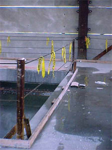
Top rails and midrails shall be at least one-quarter inch (0.6 cm) nominal diameter or thickness to prevent cuts and lacerations. If wire rope is used for top rails, it shall be flagged at not more than 6-foot intervals with high-visibility material.
When guardrail systems are used at hoisting areas, a chain, gate or removable guardrail section shall be placed across the access opening between guardrail sections when hoisting operations are not taking place.
When guardrail systems are used around holes used for the passage of materials, the hole shall have not more than two sides provided with removable guardrail sections to allow the passage of materials. When the hole is not in use, it shall be closed over with a cover, or a guardrail system shall be provided along all unprotected sides or edges.
When guardrail systems are used around holes which are used as points of access (such as ladderways), they shall be provided with a gate, or be so offset that a person cannot walk directly into the hole.
Manila, plastic or synthetic rope being used for top rails or midrails shall be inspected as frequently as necessary to ensure that it continues to meet the strength requirements of paragraph (b)(3) of this section.
The maximum size of each safety net mesh opening shall not exceed 36 square inches (230 cm) nor be longer than 6 inches (15 cm) on any side, and the opening, measured center-to-center of mesh ropes or webbing, shall not be longer than 6 inches (15 cm). All mesh crossings shall be secured to prevent enlargement of the mesh opening.
During the construction of elevator shafts, two employees may be attached to the same lifeline in the hoistway, provided both employees are working atop a false car that is equipped with guardrails; the strength of the lifeline is 10,000 pounds [5,000 pounds per employee attached] (44.4 kN); and all other criteria specified in this paragraph for lifelines have been met.
Note: If the personal fall arrest system meets the criteria and protocols contained in Appendix C to subpart M, and if the system is being used by an employee having a combined person and tool weight of less than 310 pounds (140 kg), the system will be considered to be in compliance with the provisions of paragraph (d)(16) of this section. If the system is used by an employee having a combined tool and body weight of 310 pounds (140 kg) or more, then the employer must appropriately modify the criteria and protocols of the Appendix to provide proper protection for such heavier weights, or the system will not be deemed to be in compliance with the requirements of paragraph (d)(16) of this section.
Personal fall arrest systems shall not be attached to guardrail systems, nor shall they be attached to hoists except as specified in other subparts of this Part.
When the path to a point of access is not in use, a rope, wire, chain, or other barricade, equivalent in strength and height to the warning line, shall be placed across the path at the point where the path intersects the warning line erected around the work area, or the path shall be offset such that a person cannot walk directly into the work area.
The rope, wire, or chain shall be rigged and supported in such a way that its lowest point (including sag) is no less than 34 inches (.9 m) from the walking/working surface and its highest point is no more than 39 inches (1.0 m) from the walking/working surface;
After being erected, with the rope, wire, or chain attached, stanchions shall be capable of resisting, without tipping over, a force of at least 16 pounds (71 N) applied horizontally against the stanchion, 30 inches (.8 m) above the walking/working surface, perpendicular to the warning line, and in the direction of the floor, roof, or platform edge;
The rope, wire, or chain shall have a minimum tensile strength of 500 pounds (2.22 kN), and after being attached to the stanchions, shall be capable of supporting, without breaking, the loads applied to the stanchions as prescribed in paragraph (f)(2)(iii) of this section; and
Mechanical equipment on roofs shall be used or stored only in areas where employees are protected by a warning line system, guardrail system, or personal fall arrest system.
On floors and roofs where guardrail systems are not in place prior to the beginning of overhand bricklaying operations, controlled access zones shall be enlarged, as necessary, to enclose all points of access, material handling areas, and storage areas.
On floors and roofs where guardrail systems are in place, but need to be removed to allow overhand bricklaying work or leading edge work to take place, only that portion of the guardrail necessary to accomplish that day"s work shall be removed.
Where tools, equipment, or materials are piled higher than the top edge of a toeboard, paneling or screening shall be erected from the walking/working surface or toeboard to the top of a guardrail system"s top rail or midrail, for a distance sufficient to protect employees below.
The fall protection plan shall document the reasons why the use of conventional fall protection systems (guardrail systems, personal fall arrest systems, or safety nets systems) are infeasible or why their use would create a greater hazard.

This responds to your June 1, 1999, letter to the Occupational Safety and Health Administration (OSHA), requesting information on wire rope and Crosby clips used around the perimeter of buildings as a guardrail. You also requested clarification on when employees must tie-off when a guardrail system is removed to facilitate hoisting operations. We apologize for the long delay in providing this response.
Question 1: How many Crosby clips are required to be used when setting up a wire rope guardrail? Is it permissible to splice two wire ropes by overlapping or must the connections be turned back into eyelets and properly secured?
Answer: For construction work covered by 29 CFR 1926 Subpart M, §1926.502(b) sets forth the criteria that must be met when using wire rope as a guardrail. The standard requires guardrails to meet several specific criteria. For example, 1926.502(b)(3) states that the guardrail shall be capable of withstanding, without failure, a force of at least 200 pounds applied within 2 inches of the top edge, in any outward or downward direction, at any point along the top edge. Section 1926.502(b)(4) states that when the 200 pound test load noted in §1926.502(b)(3) is applied in a downward direction, the top edge of the guardrail shall not deflect to a height less than 39 inches above the walking/working level. Section 1926.502(b)(9) states that the top rail and mid-rails shall be at least ¼-inch nominal diameter or thickness to prevent cuts and lacerations. These and other criteria must be met when using wire rope as a guardrail around the perimeter of a building.
The OSHA standard does not specify a minimum number of clips when using wire rope as a guardrail. However, as a practical matter, it is unlikely you could meet the specific requirements under §1926.502(b) unless you follow the manufacturer"s recommendations for the number of clips to be used on wire ropes of different diameters (for example, the Crosby Group Inc. general catalog, 2000 edition has tables showing their recommendations for their clips). Also, note that OSHA"s standard for rigging equipment used for material handling, 29 CFR §1926.251, has a table for the number of clips required for wire rope ½-inch and greater. Although that standard does not apply to wire rope used for guardrails, when you design a rope system to meet the §1926.502 requirements, following those tables will normally ensure that you have enough clips.
Question 2: What are the requirements for tying-off employees when a guardrail system is removed to facilitate hoisting operations? 29 CFR §1926.501(b)(3) states that, when guardrails are removed to facilitate hoisting operations, employees who have to lean out over the edge must be tied off. What about other employees, who do not have to lean out—do they have to be tied-off also?
Answer: Section 1926.501(b)(3) states that each employee in a hoist area shall be protected from falls of 6 feet or more by guardrail systems or personal fall arrest systems. It also states that, "If guardrail systems ... are removed to facilitate the hoisting operation (e.g., during landing of materials), and an employee must lean through the access opening or out over the edge of the access opening (to receive or guide equipment and materials, for example), that employee shall be protected from fall hazards by a personal fall arrest system." (59 FR 40710).
You ask if this means that the only employees who must use fall protection when the guardrails are removed are those who must lean out. The answer is no; the first sentence of §1926.501(d)(3) requires that all employees in the hoist area be protected by either a guardrail or personal fall arrest system. So, when all or part of a guardrail has been removed, all employees must be protected by a personal fall arrest system.
If you need additional information, please contact us by fax at: U.S. Department of Labor, OSHA, Directorate of Construction, Office of Construction Standards and Guidance, fax # 202-693-1689. You can also contact us by mail at the above office, Room N3468, 200 Constitution Avenue, N.W., Washington, D.C. 20210, although there will be a delay in our receiving correspondence by mail.
This chapter provides technical information about fall hazards and protection methods. The information is intended to help prepare OSHA compliance officers to conduct inspections and investigations. For convenience, links are provided to applicable OSHA standards throughout this chapter. This chapter does not cover all OSHA requirements for fall prevention/protection methods, and is not intended to serve as a comprehensive guide for developing compliant fall protection programs.
OSHA-approved state occupational safety and health plans may have different standards, but those standards must be at least as effective as federal OSHA requirements. More information about state plans is available on the OSHA website.
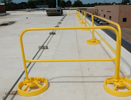
A guardrail system can be used as a barrier installed to prevent workers from falling off a work surface edge to a lower level. Guardrail systems can be used on many work surfaces, including rooftops, platforms, mezzanines, balconies, scaffolds, incomplete decked floors, catwalks, observation platforms, mobile work surfaces and ladderway points of access. Figure 1 shows a temporary guardrail system for a walkway (see 29 CFR 1926.500; 29 CFR 1926.502(b)).
Guardrails can also be used to keep workers from falling into holes or openings in decking or floors (see 29 CFR 1926.501(b)(4)(i); 29 CFR 1926.502(b); Figure 2).
A midrail, mesh, screen, or equivalent intermediate structural members installed between the guardrail system top edge and the walking/working surface when there is no wall or parapet wall at least 21 inches high (see 29 CFR 1926.502(b)(2)).
Guardrails that deflect to lower than 39 inches above the working surface when 200 pounds of pressure are applied in a downward direction (see 29 CFR 1926.502(b)(4)).
Basic guardrail components come in a variety of materials and configuration options. It is common for employers to use material available or produced at the worksite. Upright supports may be made from wood, formed metal, pipe, or composites. Wire rope is sometimes used for the top rails and midrails.
Table 1 provides guidelines as a starting point for designing guardrail systems. However, the guidelines do not provide all the information necessary to build a complete system. The components of a guardrail system must still be designed and assembled in such a way that the completed system meets all applicable requirements.
Workers installing or removing guardrails must be protected using other forms of fall protection whenever the guardrail systems are not attached securely to a stable structure.
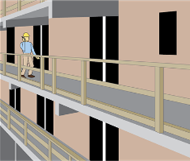
Premade or job-made guardrails can be used as temporary guardrails while more permanent structures are being installed or when the work is transient or in a space not intended as a permanent work area. For example, temporary guardrails can be used while constructing a wall, completing floor decking, or replacing a roof (see Figure 4). These guardrails are often constructed from reusable materials or premade guardrail system components as shown in Figure 4 (see 29 CFR 1926.502(b)).
Premade guardrails are particularly susceptible to damage if not handled properly when disassembled and stored. Specific handling instructions are typically included in the manufacturer’s recommended procedures for disassembling and storing the guardrail components. If railing components are bent, broken, or missing, the guardrail may not be effective. Damage is more likely to occur if the components are dropped when disassembled, transported in vehicles, or stored in areas not protected from conditions that could cause corrosion or distortion.
Scaffolds, aerial lifts, and scissor lifts can pose similar fall hazards. Guardrails, possibly in combination with additional types of fall protection systems (e.g., PFAS or restraint system), may be used to address these hazards (see 29 CFR 1926.451(g)(1); 29 CFR 1926.453(b)(2)(v); 29 CFR 1926.954(b)(3)(iii)(A)).
Effective handrails are 30 to 37 inches high and meet the guardrail strength requirements (i.e., able to withstand 200 pounds of weight applied within two inches of the top edge in any downward or outward direction at any point along the top edge) (see 29 CFR 1926.1052(c)(5), (c)(6)).
Workers are protected from the hazards associated with holes by the use of covers, personal fall protection or guardrail systems (see 29 CFR 1926.501(b)(4)(i)).
Covers for permanent holes are typically built for a specific purpose (e.g., permanent access points, manhole covers, and trap doors) and are only effective when they are properly designed and secured in place.
A warning line system is a barrier erected on a flat or low- sloped roof to warn workers that they are approaching an unprotected roof side or edge (see 29 CFR 1926.500(b); 29 CFR 1926.501(b)(10); Figure 11). A warning line system includes a line (rope, wire, or chain) and supporting stanchions (see 29 CFR 1926.502(f)(2)).
Fall restraint systems prevent the user from falling any distance. To determine the force needed to restrain a worker, consideration is given to the force that would be generated by the worker walking, leaning, or sliding down the working surface. OSHA has no specific standards for restraint systems, however, at a minimum, fall restraint systems should have the capacity to withstand at least 3,000 pounds of force or twice the maximum expected force that is needed to restrain the worker from exposure to the fall hazard.
PFAS components will be marked by the manufacturer with pertinent information specific to the equipment, such as warnings, serial/model number, capacity, and the materials used to make the component (see Figure 14). Information (e.g., proper use, maintenance, inspection) about fall protection components is typically provided in equipment manuals.
Many factors can contribute to a workers’ risk of falling from an elevated work area. Examples include precarious work positions, excessive leaning or reaching, improper work practices, unstable structures, trip hazards, slippery surfaces, and distractions.
When guardrails are not an option, personal fall protection equipment is helpful in some situations, but only when properly selected, worn, and attached to an adequate anchor point.
A lanyard is a flexible rope, wire rope, or strap which generally has a connector at each end for connecting the body belt or body harness to a deceleration device, lifeline, or anchorage point (see 29 CFR 1926.500(b)). Some manufacturers offer adjustable length lanyards. Effective lanyards are maintained in a clean, intact condition, and inspected prior to each use for wear, tear, and any obvious distortion or signs that the fall arrest (energy-absorbing) system has been activated (see 29 CFR 1926.502(d)(21)).
Lifelines function as an extension of an anchorage system, allowing an employee to move up and down (vertical lifeline) or back and forth (horizontal lifeline) across a work area. A sliding fitting (rope grab or shuttle) connects to the line and a lanyard connects the worker’s harness to that sliding fitting.
Even when a PFAS works properly, the fallen worker is still in danger. The worker"s body weight places pressure on the harness straps, which can compress the veins, and cause blood to pool, in the lower extremities and reduce blood return to the worker"s heart (see Figure 17). This condition is called suspension trauma, also known as harness hang syndrome. In medical terms, this results in orthostatic intolerance. If the pressure is not reduced promptly, the worker can lose consciousness within minutes. (See Suspension Trauma/Orthostatic Intolerance, OSHA Safety and Health Information Bulletin.
With proper personal fall protection equipment, training and practice, a fallen worker can take steps to minimize suspension trauma. Self-rescue methods allow a fallen worker to temporarily relieve pressure on the legs or in some cases to even lower himself or herself to the lower level. Self-rescue methods are discussed in detail in Washington Industrial Safety & Health Division"s Fall Protection Responding to Emergencies.
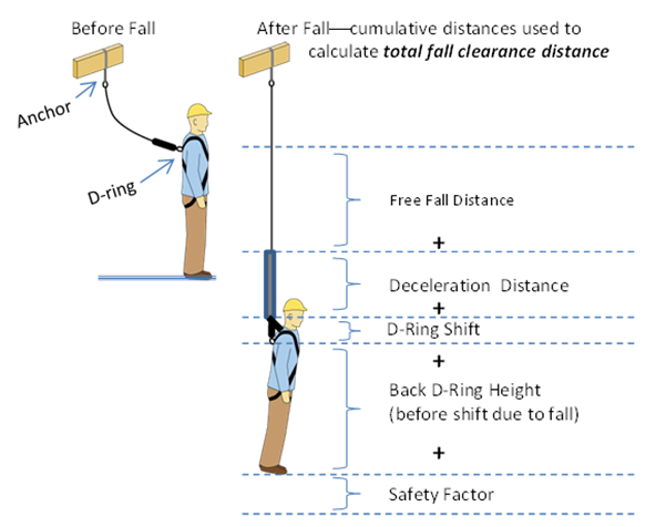
This example demonstrates that, even with a relatively short lanyard (2 feet), a fall arrest system can require considerable clearance below the elevated work area. In this case the free fall distance is 3 feet (less than OSHA"s 6-foot maximum); however, the total fall distance is 14.5 feet (more than the typical space between levels in a building under construction). A falling concrete worker could come in contact with (and be injured by) any object within the space 14.5 feet below the worker"s original position.
Personal fall arrest system, guardrail system (with a minimum 200 pound top rail capacity), or ¾ inch (1.9 centimeter) thick grab line or equivalent handhold securely fastened beside each crawling board
Both a personal fall arrest system and a guardrail system with a minimum 200 pound top rail capacity (when the platform is supported by ropes); guardrail system only (when the platform is supported by the frame structure)
Rope lifeline attaches to an anchorage at the top and hangs vertically down through the work area. Movable rope grab attaches to the rope. Lanyard connects the rope grab to workers’ harness. To move up and down the work area, the worker can slide the rope grab up and down the lifeline, then relock it in place. If the worker falls, the rope grab locks onto the rope to break the fall. This system’s effectiveness depends on how well the worker is trained to reposition the rope grab while moving about. The grab can slide off the end of the rope if the rope is too short, if a knot is not tied near the end of the rope, or if the grab is not installed properly.
The lifeline is wound on a reel and automatically extends or retracts to take up slack in the line as the worker moves about. A sudden extension in the line activates a locking mechanism that typically includes a deceleration device. Some self-retracting lanyards can be set to restrict the distance traveled and so can also function as part of a properly designed fall restraint system.
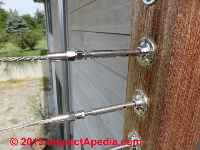
Thimbles provide a protective interface between the eye of a rope loop and a connector. They are used to prevent pinching or abrasion of the rope. The thimble needs to be firmly seated in the eye of the rope loop.
(4) For rope-grab-type deceleration systems, the length of the lifeline above the centerline of the grabbing mechanism to the lifeline"s anchorage point should not exceed 2 feet (0.61 m).
(5) For lanyard systems, for systems with deceleration devices which do not automatically limit free fall distance to 2 feet (0.61 m ) or less, and for systems with deceleration devices which have a connection distance in excess of 1 foot (0.3 m) (measured between the centerline of the lifeline and the attachment point to the body belt or harness), the test weight should be rigged to free fall a distance of 7.5 feet (2.3 m) from a point that is 1.5 feet (.46 m) above the anchorage point, to its hanging location (6 feet below the anchorage). The test weight should fall without interference, obstruction, or hitting the floor or ground during the test. In some cases a non-elastic wire lanyard of sufficient length may need to be added to the system (for test purposes) to create the necessary free fall distance.
(2) "Rope-grab-type deceleration devices." (i) Devices should be moved on a lifeline 1,000 times over the same length of line a distance of not less than 1 foot (30.5 cm), and the mechanism should lock each time.
(a) "Selection and use considerations." (1) The kind of personal fall arrest system selected should match the particular work situation, and any possible free fall distance should be kept to a minimum. Consideration should be given to the particular work environment. For example, the presence of acids, dirt, moisture, oil, grease, etc., and their effect on the system, should be evaluated. Hot or cold environments may also have an adverse effect on the system. Wire rope should not be used where an electrical hazard is anticipated. As required by the standard, the employer must plan to have means available to promptly rescue an employee should a fall occur, since the suspended employee may not be able to reach a work level independently.
(d) "Employee training considerations." Thorough employee training in the selection and use of personal fall arrest systems is imperative. Employees must be trained in the safe use of the system. This should include the following: application limits; proper anchoring and tie-off techniques; estimation of free fall distance, including determination of deceleration distance, and total fall distance to prevent striking a lower level; methods of use; and inspection and storage of the system. Careless or improper use of the equipment can result in serious injury or death. Employers and employees should become familiar with the material in this Appendix, as well as manufacturer"s recommendations, before a system is used. Of uppermost importance is the reduction in strength caused by certain tie-offs (such as using knots, tying around sharp edges, etc.) and maximum permitted free fall distance. Also, to be stressed are the importance of inspections prior to use, the limitations of the equipment, and unique conditions at the worksite which may be important in determining the type of system to use.
(e) "Instruction considerations." Employers should obtain comprehensive instructions from the supplier as to the system"s proper use and application, including, where applicable:
(6) Proper hook-up, anchoring and tie-off techniques, including the proper dee-ring or other attachment point to use on the body belt and harness for fall arrest;
(g) "Inspection considerations." As required by 1926.502(d)(21), personal fall arrest systems must be regularly inspected. Any component with any significant defect, such as cuts, tears, abrasions, mold, or undue stretching; alterations or additions which might affect its efficiency; damage due to deterioration; contact with fire, acids, or other corrosives; distorted hooks or faulty hook springs; tongues unfitted to the shoulder of buckles; loose or damaged mountings; non-functioning parts; or wearing or internal deterioration in the ropes must be withdrawn from service immediately, and should be tagged or marked as unusable, or destroyed.
(h) "Tie-off considerations." (1) One of the most important aspects of personal fall protection systems is fully planning the system before it is put into use. Probably the most overlooked component is planning for suitable anchorage points. Such planning should ideally be done before the structure or building is constructed so that anchorage points can be incorporated during construction for use later for window cleaning or other building maintenance. If properly planned, these anchorage points may be used during construction, as well as afterwards.
(i) Properly planned anchorages should be used if they are available. In some cases, anchorages must be installed immediately prior to use. In such cases, a registered professional engineer with experience in designing fall protection systems, or another qualified person with appropriate education and experience should design an anchor point to be installed.
(ii) In other cases, the Agency recognizes that there will be a need to devise an anchor point from existing structures. Examples of what might be appropriate anchor points are steel members or I-beams if an acceptable strap is available for the connection (do not use a lanyard with a snaphook clipped onto itself); large eye-bolts made of an appropriate grade steel; guardrails or railings if they have been designed for use as an anchor point; or masonry or wood members only if the attachment point is substantial and precautions have been taken to assure that bolts or other connectors will not pull through. A qualified person should be used to evaluate the suitable of these "make shift" anchorages with a focus on proper strength.
(2) Employers and employees should at all times be aware that the strength of a personal fall arrest system is based on its being attached to an anchoring system which does not reduce the strength of the system (such as a properly dimensioned eye-bolt/snap-hook anchorage). Therefore, if a means of attachment is used that will reduce the strength of the system, that component should be replaced by a stronger one, but one that will also maintain the appropriate maximum arrest force characteristics.
(3) Tie-off using a knot in a rope lanyard or lifeline (at any location) can reduce the lifeline or lanyard strength by 50 percent or more. Therefore, a stronger lanyard or lifeline should be used to compensate for the weakening effect of the knot, or the lanyard length should be reduced (or the tie-off location raised) to minimize free fall distance, or the lanyard or lifeline should be replaced by one which has an appropriately incorporated connector to eliminate the need for a knot.
(4) Tie-off of a rope lanyard or lifeline around an "H" or "I" beam or similar support can reduce its strength as much as 70 percent due to the cutting action of the beam edges. Therefore, use should be made of a webbing lanyard or wire core lifeline around the beam; or the lanyard or lifeline should be protected from the edge; or free fall distance should be greatly minimized.
(5) Tie-off where the line passes over or around rough or sharp surfaces reduces strength drastically. Such a tie-off should be avoided or an alternative tie-off rigging should be used. Such alternatives may include use of a snap-hook/dee ring connection, wire rope tie-off, an effective padding of the surfaces, or an abrasion-resistance strap around or over the problem surface.
(7) The strength of an eye-bolt is rated along the axis of the bolt and its strength is greatly reduced if the force is applied at an angle to this axis (in the direction of shear). Also, care should be exercised in selecting the proper diameter of the eye to avoid accidental disengagement of snap-hooks not designed to be compatible for the connection.
(j) "Snap-hook considerations." (1) Although not required by this standard for all connections until January 1, 1998, locking snaphooks designed for connection to suitable objects (of sufficient strength) are highly recommended in lieu of the nonlocking type. Locking snaphooks incorporate a positive locking mechanism in addition to the spring loaded keeper, which will not allow the keeper to open under moderate pressure without someone first releasing the mechanism. Such a feature, properly designed, effectively prevents roll-out from occurring.
(2) As required by 1926.502(d)(6), the following connections must be avoided (unless properly designed locking snaphooks are used) because they are conditions which can result in roll-out when a nonlocking snaphook is used:
(vi) Improper dimensions of the dee-ring, rebar, or other connection point in relation to the snaphook dimensions which would allow the snaphook keeper to be depressed by a turning motion of the snaphook.
(l) "Elongation and deceleration distance considerations." Other factors involved in a proper tie-off are elongation and deceleration distance. During the arresting of a fall, a lanyard will experience a length of stretching or elongation, whereas activation of a deceleration device will result in a certain stopping distance. These distances should be available with the lanyard or device"s instructions and must be added to the free fall distance to arrive at the total fall distance before an employee is fully stopped. The additional stopping distance may be very significant if the lanyard or deceleration device is attached near or at the end of a long lifeline, which may itself add considerable distance due to its own elongation. As required by the standard, sufficient distance to allow for all of these factors must also be maintained between the employee and obstructions below, to prevent an injury due to impact before the system fully arrests the fall. In addition, a minimum of 12 feet (3.7 m) of lifeline should be allowed below the securing point of a rope grab type deceleration device, and the end terminated to prevent the device from sliding off the lifeline. Alternatively, the lifeline should extend to the ground or the next working level below. These measures are suggested to prevent the worker from inadvertently moving past the end of the lifeline and having the rope grab become disengaged from the lifeline.
(n) "Other considerations." Because of the design of some personal fall arrest systems, additional considerations may be required for proper tie-off. For example, heavy deceleration devices of the self-retracting type should be secured overhead in order to avoid the weight of the device having to be supported by the employee. Also, if self-retracting equipment is connected to a horizontal lifeline, the sag in the lifeline should be minimized to prevent the device from sliding down the lifeline to a position which creates a swing hazard during fall arrest. In all cases, manufacturer"s instructions should be followed.
Top edge height of top rails, or equivalent guardrail system members, shall be 42 inches (1.1 m) plus or minus 3 inches (8 cm) above the walking/working level. When conditions warrant, the height of the top edge may exceed the 45-inch height, provided the guardrail system meets all other criteria of this paragraph (§ 1926.502(b)).
Midrails, screens, mesh, intermediate vertical members, or equivalent intermediate structural members shall be installed between the top edge of the guardrail system and the walking/working surface when there is no wall or parapet wall at least 21 inches (53 cm) high.
Other structural members (such as additional midrails and architectural panels) shall be installed such that there are no openings in the guardrail system that are more than 19 inches (.5 m) wide.
Guardrail systems shall be capable of withstanding, without failure, a force of at least 200 pounds (890 N) applied within 2 inches (5.1 cm) of the top edge, in any outward or downward direction, at any point along the top edge.
When the 200 pound (890 N) test load specified in paragraph (b)(3) of this section (§ 1926.502) is applied in a downward direction, the top edge of the guardrail shall not deflect to a height less than 39 inches (1.0 m) above the walking/working level. Guardrail system components selected and constructed in accordance with the appendix B to subpart M of this part will be deemed to meet this requirement.
Top rails and midrails shall be at least one-quarter inch (0.6 cm) nominal diameter or thickness to prevent cuts and lacerations. If wire rope is used for top rails, it shall be flagged at not more than 6-foot intervals with high-visibility material.
When guardrail systems are used at hoisting areas, a chain, gate or removable guardrail section shall be placed across the access opening between guardrail sections when hoisting operations are not taking place.
When guardrail systems are used around holes used for the passage of materials, the hole shall have not more than two sides provided with removable guardrail sections to allow the passage of materials. When the hole is not in use, it shall be closed over with a cover, or a guardrail system shall be provided along all unprotected sides or edges.
When guardrail systems are used around holes which are used as points of access (such as ladderways), they shall be provided with a gate, or be so offset that a person cannot walk directly into the hole.
Manila, plastic or synthetic rope being used for top rails or midrails shall be inspected as frequently as necessary to ensure that it continues to meet the strength requirements of paragraph (b)(3) of this section (§ 1926.502).
The maximum size of each safety net mesh opening shall not exceed 36 square inches (230 cm) nor be longer than 6 inches (15 cm) on any side, and the opening, measured center-to-center of mesh ropes or webbing, shall not be longer than 6 inches (15 cm). All mesh crossings shall be secured to prevent enlargement of the mesh opening.
During the construction of elevator shafts, two employees may be attached to the same lifeline in the hoistway, provided both employees are working atop a false car that is equipped with guardrails; the strength of the lifeline is 10,000 pounds [5,000 pounds per employee attached] (44.4 kN); and all other criteria specified in this paragraph for lifelines have been met.
Note: If the personal fall arrest system meets the criteria and protocols contained in Appendix C to subpart M, and if the system is being used by an employee having a combined person and tool weight of less than 310 pounds (140 kg), the system will be considered to be in compliance with the provisions of paragraph (d)(16) of this section [§ 1926.502]. If the system is used by an employee having a combined tool and body weight of 310 pounds (140 kg) or more, then the employer must appropriately modify the criteria and protocols of the Appendix to provide proper protection for such heavier weights, or the system will not be deemed to be in compliance with the requirements of paragraph (d)(16) of this section (§ 1926.502).
Personal fall arrest systems shall not be attached to guardrail systems, nor shall they be attached to hoists except as specified in other subparts of this Part.

Each suspension rope, including connecting hardware, used on non-adjustable suspension scaffolds shall be capable of supporting, without failure, at least 6 times the maximum intended load applied or transmitted to that rope.
Each suspension rope, including connecting hardware, used on adjustable suspension scaffolds shall be capable of supporting, without failure, at least 6 times the maximum intended load applied or transmitted to that rope with the scaffold operating at either the rated load of the hoist, or 2 (minimum) times the stall load of the hoist, whichever is greater.
Where scaffolds must be used in areas that the employer can demonstrate are so narrow that platforms and walkways cannot be at least 18 inches (46 cm) wide, such platforms and walkways shall be as wide as feasible, and employees on those platforms and walkways shall be protected from fall hazards by the use of guardrails and/or personal fall arrest systems.
Except as provided in paragraphs (b)(3)(i) and (ii) of this section, the front edge of all platforms shall not be more than 14 inches (36 cm) from the face of the work, unless guardrail systems are erected along the front edge and/or personal fall arrest systems are used in accordance with paragraph (g) of this section to protect employees from falling.
Each end of a platform 10 feet or less in length shall not extend over its support more than 12 inches (30 cm) unless the platform is designed and installed so that the cantilevered portion of the platform is able to support employees and/or materials without tipping, or has guardrails which block employee access to the cantilevered end.
Each platform greater than 10 feet in length shall not extend over its support more than 18 inches (46 cm), unless it is designed and installed so that the cantilevered portion of the platform is able to support employees without tipping, or has guardrails which block employee access to the cantilevered end.
When an outrigger beam is used, the shackle or clevis with which the rope is attached to the outrigger beam shall be placed directly over the center line of the stirrup.
When winding drum hoists are used on a suspension scaffold, they shall contain not less than four wraps of the suspension rope at the lowest point of scaffold travel. When other types of hoists are used, the suspension ropes shall be long enough to allow the scaffold to be lowered to the level below without the rope end passing through the hoist, or the rope end shall be configured or provided with means to prevent the end from passing through the hoist.
Ropes shall be inspected for defects by a competent person prior to each workshift and after every occurrence which could affect a rope"s integrity. Ropes shall be replaced if any of the following conditions exist:
Swaged attachments or spliced eyes on wire suspension ropes shall not be used unless they are made by the wire rope manufacturer or a qualified person.
Portable, hook-on, and attachable ladders (Additional requirements for the proper construction and use of portable ladders are contained in subpart X of this part -- Stairways and Ladders):
Ramps and walkways 6 feet (1.8 m) or more above lower levels shall have guardrail systems which comply with subpart M of this part -- Fall Protection;
Suspension ropes supporting adjustable suspension scaffolds shall be of a diameter large enough to provide sufficient surface area for the functioning of brake and hoist mechanisms.
Suspension ropes shall be shielded from heat-producing processes. When acids or other corrosive substances are used on a scaffold, the ropes shall be shielded, treated to protect against the corrosive substances, or shall be of a material that will not be damaged by the substance being used.
To reduce the possibility of welding current arcing through the suspension wire rope when performing welding from suspended scaffolds, the following precautions shall be taken, as applicable:
An insulated thimble shall be used to attach each suspension wire rope to its hanging support (such as cornice hook or outrigger). Excess suspension wire rope and any additional independent lines from grounding shall be insulated;
The suspension wire rope shall be covered with insulating material extending at least 4 feet (1.2 m) above the hoist. If there is a tail line below the hoist, it shall be insulated to prevent contact with the platform. The portion of the tail line that hangs free below the scaffold shall be guided or retained, or both, so that it does not become grounded;
Each employee on a single-point or two-point adjustable suspension scaffold shall be protected by both a personal fall arrest system and guardrail system;
Each employee on a crawling board (chicken ladder) shall be protected by a personal fall arrest system, a guardrail system (with minimum 200 pound toprail capacity), or by a three-fourth inch (1.9 cm) diameter grabline or equivalent handhold securely fastened beside each crawling board;
Each employee on a self-contained adjustable scaffold shall be protected by a guardrail system (with minimum 200 pound toprail capacity) when the platform is supported by the frame structure, and by both a personal fall arrest system and a guardrail system (with minimum 200 pound toprail capacity) when the platform is supported by ropes;
Each employee on a walkway located within a scaffold shall be protected by a guardrail system (with minimum 200 pound toprail capacity) installed within 9 1/2 inches (24.1 cm) of and along at least one side of the walkway.
Each employee performing overhand bricklaying operations from a supported scaffold shall be protected from falling from all open sides and ends of the scaffold (except at the side next to the wall being laid) by the use of a personal fall arrest system or guardrail system (with minimum 200 pound toprail capacity).
For all scaffolds not otherwise specified in paragraphs (g)(1)(i) through (g)(1)(vi) of this section, each employee shall be protected by the use of personal fall arrest systems or guardrail systems meeting the requirements of paragraph (g)(4) of this section.
When horizontal lifelines are used, they shall be secured to two or more structural members of the scaffold, or they may be looped around both suspension and independent suspension lines (on scaffolds so equipped) above the hoist and brake attached to the end of the scaffold. Horizontal lifelines shall not be attached only to the suspension ropes.
When lanyards are connected to horizontal lifelines or structural members on a single-point or two-point adjustable suspension scaffold, the scaffold shall be equipped with additional independent support lines and automatic locking devices capable of stopping the fall of the scaffold in the event one or both of the suspension ropes fail. The independent support lines shall be equal in number and strength to the suspension ropes.
Vertical lifelines, independent support lines, and suspension ropes shall not be attached to each other, nor shall they be attached to or use the same point of anchorage, nor shall they be attached to the same point on the scaffold or personal fall arrest system.
Guardrail systems installed to meet the requirements of this section shall comply with the following provisions (guardrail systems built in accordance with Appendix A to this subpart will be deemed to meet the requirements of paragraphs (g)(4)(vii), (viii), and (ix) of this section):
Guardrail systems shall be installed along all open sides and ends of platforms. Guardrail systems shall be installed before the scaffold is released for use by employees other than erection/dismantling crews.
The top edge height of toprails or equivalent member on supported scaffolds manufactured or placed in service after January 1, 2000 shall be installed between 38 inches (0.97 m) and 45 inches (1.2 m) above the platform surface. The top edge height on supported scaffolds manufactured and placed in service before January 1, 2000, and on all suspended scaffolds where both a guardrail and a personal fall arrest system are required shall be between 36 inches (0.9 m) and 45 inches (1.2 m). When conditions warrant, the height of the top edge may exceed the 45-inch height, provided the guardrail system meets all other criteria of paragraph (g)(4).
When midrails, screens, mesh, intermediate vertical members, solid panels, or equivalent structural members are used, they shall be installed between the top edge of the guardrail system and the scaffold platform.
When midrails are used, they shall be installed at a height approximately midway between the top edge of the guardrail system and the platform surface.
When screens and mesh are used, they shall extend from the top edge of the guardrail system to the scaffold platform, and along the entire opening between the supports.
Each toprail or equivalent member of a guardrail system shall be capable of withstanding, without failure, a force applied in any downward or horizontal direction at any point along its top edge of at least 100 pounds (445 n) for guardrail systems installed on single-point adjustable suspension scaffolds or two-point adjustable suspension scaffolds, and at least 200 pounds (890 n) for guardrail systems installed on all other scaffolds.
Midrails, screens, mesh, intermediate vertical members, solid panels, and equivalent structural members of a guardrail system shall be capable of withstanding, without failure, a force applied in any downward or horizontal direction at any point along the midrail or other member of at least 75 pounds (333 n) for guardrail systems with a minimum 100 pound toprail capacity, and at least 150 pounds (666 n) for guardrail systems with a minimum 200 pound toprail capacity.
Suspension scaffold hoists and non-walk-through stirrups may be used as end guardrails, if the space between the hoist or stirrup and the side guardrail or structure does not allow passage of an employee to the end of the scaffold.
Manila or plastic (or other synthetic) rope being used for toprails or midrails shall be inspected by a competent person as frequently as necessary to ensure that it continues to meet the strength requirements of paragraph (g) of this section.
In addition to wearing hardhats each employee on a scaffold shall be provided with additional protection from falling hand tools, debris, and other small objects through the installation of toeboards, screens, or guardrail systems, or through the erection of debris nets, catch platforms, or canopy structures that contain or deflect the falling objects. When the falling objects are too large, heavy or massive to be contained or deflected by any of the above-listed measures, the employer shall place such potential falling objects away from the edge of the surface from which they could fall and shall secure those materials as necessary to prevent their falling.
Where tools, materials, or equipment are piled to a height higher than the top edge of the toeboard, paneling or screening extending from the toeboard or platform to the top of the guardrail shall be erected for a distance sufficient to protect employees below; or
When canopies are used on suspension scaffolds for falling object protection, the scaffold shall be equipped with additional independent support lines equal in number to the number of points supported, and equivalent in strength to the strength of the suspension ropes.
Re: Wire rope clips on suspension scaffolds; safety latches on large crane hooks; hanging scaffolds - order of assembly; jobsite fabricated lifting accessories - criteria; and horizontal lifelines: use of wire rope clips, anchorages, number of persons allowed to be connected, requirements relating to sag, and use of synthetic rope.
This is in response to your facsimile dated November 14, 2003, to the Occupational Safety and Health Administration (OSHA). We have paraphrased your questions as follows:
Question 1(a) - (c): When using horizontal lifelines as part of personal fall arrest systems, what type of wire rope clips does OSHA require, and how many clips must be used? Additionally, what are the horizontal spacing criteria for the uprights?
Subpart M does not specify what type of wire rope clip or how many clips/clamps must be used when installing a horizontal lifeline. However, under §1926.502(d)(8), these decisions must be made under the supervision of a qualified person when the system is designed. The determination of the horizontal spacing criteria for uprights is also left to the qualified person"s supervisory approval.1
In an August 28, 2000 letter to Mr. Troxell2, we addressed the related issue of using wire rope clips on a wire rope guardrail. In that letter, we cautioned that, as a practical matter, it is unlikely that the criteria requirements for guardrails under §1926.502(b) could be met unless the manufacturer"s recommendations for the number of clips to be used on wire ropes of different diameters were followed (for example, the Crosby Group, Inc., general catalog 2000 edition, has tables showing their recommendations for their clips). We also pointed out that OSHA"s standard for rigging equipment used for material handling, 29 CFR 1926.251, has a table showing the number of clips required for wire rope ½-inch and greater. We noted that although that standard does not apply to wire rope used for guardrails, when designing a rope system to meet the §1926.502 guardrail requirements, following the tables at §1926.251 will normally ensure that there will be enough clips.
The forces exerted on a horizontal lifeline are substantially greater than those on a typical guardrail. Therefore, the system designer needs to ensure that the number, type, and location of clips will withstand the anticipated forces and meet the performance requirements in §1926.502 for horizontal lifelines.
Question 2: For a horizontal lifeline used as part of a personal fall arrest system during steel erection work, how tight should the lifeline be, and may synthetic rope be used for the horizontal lifeline?
Therefore, a qualified person is required to determine how tight the lifeline should be based on site-specific factors. No other requirements are imposed by OSHA regarding the tightness of the lifeline, so long as it comports with a safety factor of at least two.
With regard to the use of synthetic ropes, §1926.502(d)(14) specifies that, when using non-wire rope, synthetic rope (rather than nature fiber rope) must be used:
Question 4: Are there OSHA standards that specify criteria for constructing jobsite fabricated rigging equipment such as an equalizing beam, lifting beam, spreader beam, equalizing plates, tee lugs, lifting lugs, and welded scaffold brackets?
The only OSHA construction standards that contains specific criteria related to the construction of special custom design lifting accessories is 29 CFR 1926.251(a)(4), which states:
Question 5: Under §1926.451(d)(12)(v) and (vi), when wire rope clips are used on suspension scaffolds, "(v) U-bolt clips shall not be used at the point of suspension for any scaffold hoist," and "(vi) when U-bolt clips are used, the U-bolt shall be placed over the dead end of the rope, and the saddle shall be placed over the live end of the rope." Does §1926.451(d)(12)(v) contradict paragraph (d)(12)(vi)?
No. By its terms, §1926.451(d)(12)(v) prohibits the use of U-bolt clips at the point of suspension for any scaffold. The scaffold standard does not prohibit using U-bolt clips elsewhere. However, when using them elsewhere, under §1926.451(d)(12)(vi), the U-bolt must be placed over the dead end of the rope, and the saddle placed over the live end of the rope.
Question 6: Under §1926.251(c)(4)(iii), are eyes in wire rope bridles and slings or bull wires formed by wire rope clips permitted when used to lift scrap boxes or pendants?
This provision specifically prohibits eyes in wire rope bridles and slings or bull wires being formed by wire rope clips. There is no exception for lifting scrap boxes or pendants.
There are no OSHA standards setting criteria for horizontal high-lines. However, an employer"s use of a horizontal high-line must be in accordance with its obligations under Section 5(a)(1) of the Occupational Safety and Health Act (the "General Duty Clause"), which states:
In our view, the industry recognizes that the following engineering factors, among others, must be considered when designing horizontal high-lines: the span and sag of the wire rope line, the weight of the load being lifted, the initial tension of the rope line, and the size of the columns.
OSHA requirements for a safety latch on hooks do not depend of the size of the hook but rather the activity for which the hook is being used. Safety latches on hooks are required in two instances:
Knotting wire rope compromises the integrity of the strength of the wire rope and is therefore prohibited. Based on the picture provided, which showed a knot in wire rope secured by a U-bolt clip, this practice would be in violation of §1926.251(c)(3).
Question 10: Do OSHA standards require the attachment of an orange and white flag to the highest point of a crane that is being used in the vicinity of an airport?
There are no OSHA standards that require the highest point of a crane to be marked to enhance visibility to air traffic. However, the use of a crane in the vicinity of an airport may be subject to requirements set by other regulatory agencies, such as the Federal Aviation Administration.
Question 11: Do OSHA standards specify a particular anchorage point for connecting the lanyards of workers on crane suspended personnel platforms? Do the standards limit the number of such workers that can be attached to an anchorage point?
If you need additional information, please contact us by fax (202-693-1689) at: U.S. Department of Labor, OSHA, Office of Construction Standards and Guidance. You can also contact us by mail at U.S. Department of Labor, OSHA, Office of Construction Standards and Guidance, Room N3468, 200 Constitution Avenue, N.W., Washington, D.C. 20210, although there will be a delay in our receiving correspondence by mail.
Proper operation required. Personnel hoisting operations must not begin unless the devices listed in this section are in proper working order. If a device stops working properly during such operations, the operator must safely stop operations. Personnel hoisting operations must not resume until the device is again working properly. Alternative measures are not permitted. (See § 1926.1417 for tag-out and related requirements.)
The personnel platform itself (excluding the guardrail system and personal fall arrest system anchorages), must be capable of supporting, without failure, its own weight and at least five times the maximum intended load.
The personnel platform must be equipped with a guardrail system which meets the requirements of subpart M of this part, and must be enclosed at least from the toeboard to mid-rail with either solid construction material or expanded metal having openings no greater than ½ inch (1.27 cm). Points to which personal fall arrest systems are attached must meet the anchorage requirements in subpart M of this part.
In addition to the use of hard hats, employees must be protected by overhead protection on the personnel platform when employees are exposed to falling objects. The platform overhead protection must not obscure the view of the operator or platform occupants (such as wire mesh that has up to ½ inch openings), unless full protection is necessary.
Rope bridle. When a rope bridle is used to suspend the personnel platform, each bridle leg must be connected to a master link or shackle (see paragraph (g)(1) of this section) in a manner that ensures that the load is evenly divided among the bridle legs.
Rigging hardware (including wire rope, shackles, rings, master links, and other rigging hardware) and hooks must be capable of supporting, without failure, at least five times the maximum intended load applied or transmitted to that component. Where rotation resistant rope is used, the slings must be capable of supporting without failure at least ten times the maximum intended load.
Safety devices and operational aids required by this section are activated and functioning properly. Other safety devices and operational aids must meet the requirements of § 1926.1415 and § 1926.1416.
The platform must be hoisted a few inches with the personnel and materials/tools on board and inspected by a competent person to ensure that it is secure and properly balanced.
This is in response to your letter of June 29, concerning the acceptability of wire rope and/or cable as a method of perimeter protection for a building under construction.
The use of wire ropes as top rails and intermediate rails of guardrail systems used for perimeter protection or for guardrails used on scaffolding meeting the equivalent requirements of 29 CFR 1926.500(d)(1) and 29 CFR 1926.451(a)(5) is acceptable provided it meets the following guidelines:
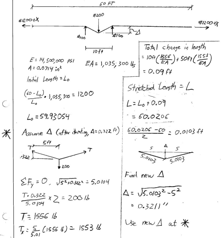
(3) The maximum deflection of the top rail when a load of 200 pounds is applied in any direction at any point on the top rail shall not exceed 3 inches in one direction which includes the free hanging sag in the wire rope.

“Metal decking” means a commercially manufactured, structural grade, cold rolled metal panel formed into a series of parallel ribs; for this section, this includes metal floor and roof decks, standing seam metal roofs, other metal roof systems and other products such as bar gratings, checker plate, expanded metal panels, and similar products. After installation and proper fastening, these decking materials serve a combination of functions including, but not limited to: a structural element designed in combination with the structure to resist, distribute and transfer loads, stiffen the structure and provide a diaphragm action; a walking/working surface; a form for concrete slabs; a support for roofing systems; and a finished floor or roof.
“Safety deck attachment” means an initial attachment that is used to secure an initially placed sheet of decking to keep proper alignment and bearing with structural support members.
(B) A firm, properly graded, drained area, adequately compacted to support the intended loads, readily accessible to the work with adequate space for the safe storage of materials and the safe operation of the erector"s equipment.
(B) The perimeter columns have holes or other devices in or attached to perimeter columns at 42-45 inches (107-114 cm) above the finished floor and the midpoint between the finished floor and the top cable to permit installation of perimeter safety cables (wire rope) required by subsection (l)(3) of this section, except where constructibility does not allow.
(1) The derrick or erection floor shall be solidly planked or decked except for access openings. Planking or decking of equivalent strength, shall be of proper thickness to carry the working load. Planking shall be not less than 2 inches thick full size undressed, and shall be laid tight. Both planking and decking shall be secured.
(3) The exposed edges of all temporary planked and metal decked floors at the periphery of the building, or at interior openings, such as stairways and elevator shafts shall be protected by a single 3/8-inch minimum diameter wire rope of 13,500 pounds minimum breaking strength located between 42 and 45 inches above design finish floor height. Other guardrail protection may be used if equal fall protection is provided.
(4) The employer shall document the reasons why the use of conventional fall protection systems (guardrails, personal fall arrest systems, positioning device systems, fall restraint systems or safety nets) are infeasible or why their use would create a greater hazard.
(o) Custody of guardrail systems. Wire rope or other guardrail protection provided by the steel erector shall remain in the area where steel erection activity has been completed, to be used by other trades, only if the controlling contractor or its authorized representative:
(2) Has inspected and accepted control and responsibility of the wire rope or other guardrail protection prior to authorizing persons other than steel erectors to work in the area.
(B) The use and operation of guardrail systems (including perimeter safety cable systems), personal fall arrest systems, positioning device systems, fall restraint systems, safety net systems, and other protection to be used;


 8613371530291