
overhead crane wire rope changing procedure free sample
Buying new crane ropes is a detailed and thorough process. While it may be time-consuming, wire rope replacement prioritizes safety for your workers, minimizes downtime on a jobsite, maximizes the lifespan of the crane and avoids the costly and time-consuming process of getting correct rope onsite and respooling your crane.
Sometimes, it can seem like the wire rope buying process is overly complicated. This is done on purpose to avoid as many issues as possible when the new rope is installed. The reason for that is so buyers avoid putting the wrong types of ropes on cranes and unnecessarily increasing the risk of injuries to workers or damage to loads being lifted. The processes are to make sure to prevent that added risk and put the correct rope on the correct machine, per Original Equipment Manufacturer (OEM) specifications.
Wire rope specialists ask these questions to understand your circumstances and what your needs are. With this information, they are better prepared to get the absolute correct rope.
Most of the time, the customer should have access to their crane’s operations manual that will show what rope diameter and length is specified. The customer may have to measure or come up with his own calculations on length. The crane manufacturer is going to make a specific drum for that specific type of wire rope.
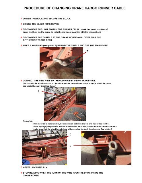
The rope has to be specific to the lagging of the drum for that machine, which is why there are multiple variations for each size of wire rope because each kind is specific to the type of crane, and it shouldn’t be substituted. Mazzella will only install the rope that is the correct brand and tolerance on a particular crane.
Ordering the correct crane rope will prevent crane rope damage. The wrong rope could cause damage to the equipment, and at worst, boom failure. On the less severe side, you will have bad performance or it might not work at all. You could have twist and/or spooling issues. That could lead to the crane failing altogether, which creates downtime as you wait for the correct wire rope to be ordered/delivered and installed.
Many crane owners are working for somebody else when they’re doing jobs, so if the rope doesn’t work, they’re paying for work that is not getting done and falling behind schedule.
On the more severe side, you could total your crane and/or irreparably damage the load being lifted if you use the wrong wire rope. In the worst-case scenario, using the incorrect rope could result in severe injury and/or the loss of life.
Sometimes, customers assume that there’s a one-size-fits-all replacement, that if it’s a non-rotating rope, it should work on every application. There’s a lot of misinformation on what will work and what won’t work. With our experience and access to all brands of wire rope, Mazzella guarantees we can get you the right rope for your cranes. If Mazzella isn’t comfortable with the project, we won’t supply the wire rope.
If the wrong wire rope is ordered and delivered, it could be hours or days before the correct rope is on location. Especially with a lot of the larger cranes, manufacturers are shipping model-specific ropes all over the country, and depending on location and money, that could cause delays on your jobsite.
With our large inventory of rope, Mazzella can have a new spool of wire on a truck and out for delivery in a matter of hours. Avoid the pitfalls of ordering the wrong crane rope and you’ll have a new spool of wire rope on its way. Once the order process is done, what can your company do to prepare for delivery and installation?
It is a good idea to give management the proper notice of when the installer will be on-site, have the necessary technicians on-site to help the installer with the rope replacement and make sure the installer/technicians have a clear working space.
There’s a lot of downtime associated with making a mistake in the preparation process, so the more prepared you can be for the install, the better. You don’t want a situation where your crane is inactive because of an oversight or completely avoidable situation.
Also, Mazzella recommends you measure your sheaves with a sheave gauge. A sheave gauge will help you measure the wear of the root, the amount of wear on the groove wall and the diameter of the wire rope.
After ordering the correct rope and having the requisite space and approval for installation, how long will it take to remove and replace the old rope when the technician, assistants and supplies arrive onsite? For some small cranes, the timeframe could be as little as 45 minutes, but for larger cranes, removing the old rope and installing the new one could be a several-hour process.
There’s a lot of factors that go into a successful crane rope installation. The most important thing is the quicker your supplier responds to your order and gets a rope on location, the quicker that rope gets installed properly, saving time and money. Downtime is the key, and it could cost companies tens of thousands of dollars per day if their crane(s) are inoperable.
Once a new crane rope is installed, a break-in period or tension period is recommended to make sure everything is performing correctly, and help you avoid shock-loading the newly installed wire rope. The break-in period is recommended because installation and spooling equipment are not going to put adequate tension on the rope. A break-in period consists of putting a low percentage of the working load limit weight on the rope for several lift cycles, and running the blocks up to the boom length (working height) and back down. For the most specific guidelines on the breaking-in process for your new wire rope, refer to the manufacturer’s recommendations.
If a brand-new wire rope on a crane is not broken in properly before lifting a large load, it potentially could damage the rope and render useless the equipment that was just installed on your machine.
When Mazzella fulfills a crane ropes order, it is not just about the sale and the bottom line. While we’re in the business of selling crane ropes, we’re also in the business of building relationships and trust. We are committed to making sure you get the correct products for the right applications.
Crane rope issues don’t just happen 9-to-5 during the normal work week. They happen Friday nights, holidays, weekends and early mornings. They’re always on the clock, and it is just about being honest with the customer and letting them know, they type of rope that is required. That honesty and trust is of utmost importance for the safety of your workers and the proper maintenance of your cranes.
Mazzella has one of the largest crane ropes inventories in the United States. The company provides wire rope assemblies and manufactures bridge cables, crane cables, steel mill cables and thousands of OEM assemblies in sizes from ¼ to 3-inch diameter and 9 to 52 millimeter diameter, domestic and non-domestic and in stock and ready for same or next-day shipment.
吊,搬送する大型天井クレーン等の分野で利用される。Description: TECHNICAL FIELD The present invention relates to a method for replacing a wire rope of a crane, and more particularly, to efficiently use an old wire rope wound around a hoisting drum installed on a crane. The present invention relates to a method of replacing a new wire rope with an old wire rope which can be automatically wound on the ground. This is used in the field of large overhead cranes that suspend and transport heavy objects such as coiled steel plates and ingots.
えたフックブロック8を懸吊している。A wire rope wound around a hoisting drum such as a large overhead crane installed in a rolling mill of a steel mill is, for example,
いう)までも解く。In such an overhead crane, replacement work of the old wire rope 6 has been conventionally performed as follows. As shown in FIG. 9, first, the hoisting drum 5 is rotated in the hoisting direction (the direction opposite to the arrow 42), and the hoisting drum 5 is rotated.
The views of the old wire rope 6 are sequentially solved from the winding grooves 5c and 5d in the left-right inverted spiral shape engraved on the hook block 8, and the hook block 8 is lowered onto the support base 9 placed on the ground and firmly mounted.
Remove one end 6a (see FIG. 10) of the old wire rope 6 that is hung on the floor, tie the end 6a with a cremona rope (not shown), and lower it to the ground. Then, the Cremona rope is removed, and one end of the new wire rope 10 wound around the feeding means 11 arranged in advance on the ground and one end 6a of the old wire rope 6 are connected by a connecting fitting (not shown) or the like. . After that, the hoisting drum 5 is rotated in the hoisting direction 42, and the new wire rope 10 is started to be pulled up to the hoisting drum 5, while the old wire rope 6 is wound about three times around the winding groove 5d of the hoisting drum 5. Let This is to secure a frictional force such that the old wire rope 6 and the new wire rope 10 do not slip on the hoisting drum 5 when the hoisting drum 5 is subsequently rotated in the hoisting direction 42 and the old wire rope 6 is paid out. This is to keep it. After that, the other end 6b (the first end) of the old wire rope 6 hooked on the fixture 5b provided on the other end of the hoisting drum 5 (first
戻し、再度、上記と同じ作業を繰り返す。The other end of the old wire rope 6 is tied with a cremona rope or the like, and in this state, the hoisting drum 5 is further rotated in the hoisting direction 42, while the other end is guided so as not to bounce, while the club 4 is being guided. The old wire rope 6 is let out to the ground through the handrail 4a, and the worker waiting on the ground bundles the old wire rope 6 in a ring shape. During this operation, the old wire rope 6 wound around the winding drum 5 moves in the direction of the arrow 44 along the spiral winding groove 5d. When the wound portion of the old wire rope 6 reaches the central position approaching the winding groove 5c of the reverse spiral, there is no winding allowance for the old wire rope 6 to move, and at that time, the rotation of the hoisting drum 5 To stop. The old wire rope 6 in the wound state is loosened on the hoisting drum 5 by the operator"s manual work so as to float from the winding groove 5d, and the old wire rope 6 is left as it is at the left end of the winding groove 5d where the fixture 5b is located. Return to and repeat the same operation as above.
了される。When the connection between the new wire rope 10 and the old wire rope 6 reaches the upper position 43 of the hoist drum 5 by sequentially tracing the hook block 8 and the upper sheave 7 (see FIG. 10) by such work. The rotation of the hoisting drum 5 is stopped, the connecting portion is disconnected, and one end of the new wire rope 10 is hooked on the fixture 5b of the hoisting drum 5. The other end 6b of the old wire rope 6
Is tied with a cremona rope, and it is lowered to the ground, and the last part of the old wire rope 6 is also bundled into a ring on the ground. On the other hand, the other end of the new wire rope 10 is removed from the feeding means 11, the other end is tied with a cremona rope or the like and pulled up onto the club 4, and the other end is hooked on the fixture 5a of the hoisting drum 5. After the hoisting drum 5 is rotated in the hoisting direction 42 and the new wire rope 10 is additionally wound at both ends of the hoisting drum 5, the hoisting drum 5 is further rotated in the hoisting direction, whereby the new wire rope 10 Is wound around the hoisting drum 5, and the hook block 8 rises. In this way, the replacement work of the old wire rope 6 and the new wire rope 10 is completed.
非常に煩わしいものであった。In such a conventional replacement method, while rotating the hoisting drum 5 at the high position of the ceiling part, the old wire rope 6 is unwound to the ground, while the unwound old wire rope 6 is bundled by the operator on the ground. It was being done. For large overhead cranes, the diameter of the wire rope used for them is as large as 25 mm to 40 mm, and the work of bundling them is not very efficient because it requires a lot of manpower and is a very heavy work. In addition, it is necessary for the bundling operator and the crane operator to work while constantly signaling each other.
提案した。For this reason, the applicant of the present invention, after fixing the hook block to the ground, connects one end of the old wire rope to the new wire rope and connects the other end of the old wire rope to the winding means separately prepared. JP-A-63-17792 proposes a method for replacing the wire rope of a crane, in which the old wire rope is wound up only by the pulling force driven by the winding means without driving the hoisting drum. did.
善が強く望まれていた。In the above method, the pulling force of the winding means arranged on the ground acts on the entire wire rope, and by extension, the old wire rope in the portion stretched between the upper sheave and the hook block is also directly affected. It was necessary to fix the hook block particularly firmly. In addition, the strength of the winding means must be increased in order to obtain a sufficient tensile force, and the drive source requires considerably large power. This is even more so when the wire rope is thick and heavy, which causes problems such as an increase in the size of the device and an increase in cost, and a restriction on the work space. Further, since a large tension acts on the wire rope, the connection portion between the new wire rope and the old wire rope may be disconnected, and improvement of the work has been strongly desired.
ープ取替方法を提供することである。The present invention has been made in consideration of such circumstances, and an object of the present invention is not to require a compact and large space, to keep a large tension applied to the wire rope at all times, and to make the wire rope thick. It is an object of the present invention to provide a method for replacing a wire rope of a crane, in which the safety of the replacement work is highly secured and the wire rope can be efficiently replaced with a new wire rope.
けるワイヤロープの取替方法に適用される。INDUSTRIAL APPLICABILITY The present invention is applied to a method for replacing a wire rope in a crane equipped with a hoisting drum for winding a wire rope, which is installed on a truck traveling on a rail.
It is lowered to the ground by rotating in the winding direction (the direction opposite to the arrow 42), and is unwound from the hoisting drum 5 to the old winding of the old wire rope 6. The one end 6a of the old wire rope 6 is removed from one end of the hoisting drum 5, and the one end 6a of the old wire rope 6 is lowered to the ground and connected to one end of the new wire rope 10 wound around the feeding means 11. Next, the hoisting drum 5 is rotated in the hoisting direction 42, and the old wire rope 6 is wound around the hoisting drum 5 a predetermined number of times. Remove the other end 6b. Rotate the hoisting drum 5 further in the hoisting direction 42,
The new wire rope 10 is started to be pulled up to the hoisting drum 5, and the other end 6b of the old wire rope 6 is fed to the ground. The other end 6b of the old wire rope 6 is connected to the rotary table 17 arranged on the ground, and the winding direction of the winding drum 5 thereafter is increased.
The old wire rope 6 is fed to the ground by rotating the old wire rope 6 and the rotation speed of the rotary table 17 is adjusted so that the old wire rope 6 has a desired winding diameter without tension. That is, the ropes 6 are stacked in a ring shape and bundled.
うにしてもよい。Further, referring to FIG. 5, the iron cage 18 having a cylindrical iron cage 18a surrounded by the old wire ropes 6 which are stacked in a ring shape is detachably provided on the rotary table 17 and is fed to the ground. The old wire rope 6 may be bundled in a ring shape by the rotation of the rotary table 17 while preventing the winding wire of the old wire rope 6 from being disturbed by the cylindrical basket portion 18a.
While contacting the old wire rope 6 that has been fed to the ground through the upper opening of 8c, to the ring-shaped pipe material that is located at the boundary between the truncated cone-shaped groin portion 18b and the truncated cone-shaped small groin portion 18c. Alternatively, the old wire ropes 6 may be stacked and bundled in a ring shape by the rotation of the rotary table 17.
とした巻き取りを実現することができる。According to the present invention, one end of an old wire rope removed from a hoisting drum is connected to a new wire rope, and the old wire rope is wound around the hoisting drum a predetermined number of times, and then the hoisting drum is rotated in a hoisting direction. Since the other end of the old wire rope is drawn to the ground while being made to move, the old wire rope can be reliably drawn without slipping, and the new wire rope can be wound around the hoisting drum. Then, the old wire rope is extended to the other side by the rotation of the hoisting drum in the winding direction and the rotation speed of the rotary table is adjusted to connect the old wire rope to the movement of the rotary table arranged on the ground. Since the wire rope is wound, it is possible to efficiently stack the old wire ropes in a loop so that the old wire ropes have a desired winding diameter without exerting a large tension on the wire ropes. That is, if the rotation speed of the rotary table is increased, the winding can be made thinner, and if the winding is tightened too much, it can be slowed down and corrected, or a large bunch of wheels can be stacked. Orderly winding can be achieved with any diameter.
ないものとしておくことができる。If a carcass with a cylindrical cage that surrounds the old wire ropes that are bundled in a ring shape is detachably attached to the rotating table, the disorder of the winding appearance of the old wire ropes that have been fed to the ground will be cylindrical. Part is prevented by
The old wire rope can be smoothly looped and bundled by rotating the rotary table. For example, if the old wire rope suddenly jumps out, the cylindrical cage prevents it. Further, even if the ring-shaped bundle is greatly tilted, it is prevented from deviating from the turntable. Of course, the old wire ropes can be bundled compactly to facilitate the subsequent treatment, and the winding means can be made to require no space.
しておきたい場合に都合がよい。By forming a truncated cone-shaped basket on the upper part of the cylindrical basket, the old wire rope that is fed to the ground is brought into contact with the inner surface of the truncated cone and the rotary table rotates to form a ring shape. Can be stacked and bundled. For example, even if a situation occurs in which the old wire rope is excessively shaken by centrifugal force or the like due to the rotation of the turntable, the wound form after that is not greatly impaired. This is convenient when it is desired to keep the winding diameter large.
同心状の巻取り姿となるよう誘導することができる。A small frustoconical small squirrel cage is formed in the upper part of the frustoconical squirrel cage, and the old wire rope that is fed to the ground through the upper opening of the frustoconical small squirrel cage is cut into a truncated cone shape. The old wire ropes can be looped and bundled by rotating the rotary table by contacting them in a ring-shaped pipe shape located at the boundary between the pallet cage and the truncated cone small pallet cage. Not only does the frustoconical small squirrel cage guide the movement of the old wire rope to suppress unnecessary fluctuations, but the frustoconical small squirrel cage is narrower toward the top to allow the old wire rope to be thin. It is possible to prevent the body from jumping out of the body and guide it to have a concentric winding shape.
等の重量物を懸吊,搬送するものである。The wire rope replacement method shown in the present embodiment efficiently uses a thick and rigid old wire rope wound around the hoisting drum of a crane by using a vertically-shaped winding means that is compactly formed. It is a new wire rope that can be replaced and the old wire rope can be wound and bundled without requiring a large amount of power. The crane to which this wire rope replacement method is applied is, for example, a large overhead crane 1 as shown in FIG.
ーブ7を介してフックブロック8を懸吊している。As shown in FIG. 1, rails 3a, 3a are laid on a girder 3 of the overhead crane 1, and a club 4 as a truck moving on the rails 3a is rotated by a drive source (not shown). The hoisting drum 5 is stationary. The winding drum 5 is provided with spiral winding grooves 5c, 5d in the opposite direction on the left and right, and both ends 6a of the old wire rope 6 wound along the winding grooves 5c, 5d. As shown in FIG. 10, the wires 6b are hooked at both ends of the hoisting drum 5, and the wire ropes 6 thereof are hooked via the upper sheave 7 arranged at the lower part of the hoisting drum 5. Is suspended.
ブブロック(図示省略)に軸支されている。The hook block 8 pivotally supports four movable pulleys 8A, 8A, and a load hanging hook 8a (see FIG. 1) is hung at the bottom thereof. That is, the fixtures 5a and 5b for attaching the wire rope are provided at both ends of the hoisting drum 5, and the wire rope in which the hook block 8 is suspended via the upper sheave 7 on the fixtures 5a and 5b. One end 6a and the other end 6b of 6,
を巻き取る巻取手段12とにより構成される。As shown in FIG. 1, the wire rope replacement device has a support base 9 placed on the ground for mounting the hook block 8 and one end 6a of the old wire rope 6 removed from the hoisting drum 5. A feeding means for feeding the new wire rope 10 to be connected
9上でも充分な安定を得ることができる。The support base 9 is a base with four legs having a mounting surface on the top, and is simple enough for an operator to easily carry. As will be described later, since the old wire rope 6 to be replaced is unwound by the hoisting drum 5, a large external force does not act on the hook block 8 via the old wire rope 6 during the replacement work. It is possible to obtain sufficient stability even on a simple support base 9.
を、順次繰り出すことができるようになっている。The feeding means 11 has a rotatable disc (not shown) inside an annular base 14 having a plurality of shelves 13 arranged on the outer periphery thereof, and a core member protruding in the center of the disc. A new wire rope 10 is coiled around and mounted on a disk around 15
と共に駆動源19により回転されるようになっている。The winding means 12 is, as shown in FIGS. 4 and 5, a vertical guide shaft 16 for guiding the old wire rope 6 unwound from the winding drum 5 to be wound up.
In order to enclose the horizontal rotary table 17 that rotates with the guide shaft 16 to receive the old wire rope 6 in a ring shape, and the old wire rope 6 that is detachably provided on the rotary table 17 and is bundled in a ring shape. And a vertical frame 18 to be arranged, and the rotary table 17 is provided with a guide shaft 16
けている。The iron cage 18 is a ring-shaped pipe material 24 arranged laterally so as to surround the outer circumference of the old wire rope to be wound up.
Is provided with a cylindrical cross-shaped cage 18a, which is a combination of the pipe members 25 arranged in the vertical direction so as to intersect with each other, and on the upper part thereof, a two-pointed truncated conical cross-shaped cage for introducing and guiding an old wire rope. The portion 18b is provided with a truncated cone small cross-section basket 18c.
けられている。By the driving force of the vertical geared motor 19 described above, the guide shaft 16 integrated with the rotary table 17 and the cross cage 18 are rotated, and the old wire rope introduced from the upper opening of the truncated cone small cross cage 18c. 6 (see FIG. 1) can be bundled around the guide shaft 16 in a ring shape. The angle members 30 are radially arranged on the rotary table 17 so that a small space is formed under the bundled old wire ropes so that the bundled old wire ropes can be easily taken out. Also,
Has only to have an output enough to stack and bundle the fed old wire ropes 6, and the output is relatively small such as 3.7 kw. Cross cage 18 and rotary table
The rotation speed of the rotary table 17 can be adjusted according to the descending speed of the old wire rope 6 fed out from the table, so that the old wire rope 6 can be bundled without wasting space, and the old wire rope 6 can be bundled by changing the rotation speed. The ring diameter can be changed arbitrarily each time. Further, the operator can carry the operation box 33 with the frequency meter and operate it in any safe place.
に説明する。The replacement work of the old wire rope 6 and the new wire rope 10 by the wire rope replacement device thus configured will be described below.
置した支持台9上にフックブロック8を載置する。(A) First, as shown in FIG. 1, the old wire rope 6 is unwound by rotating the hoisting drum 5 in the lowering direction (the direction opposite to the arrow 42), and the hook block 8
端に、連結金具(図示せず)等で接続する。(C) The one end 6a of the old wire rope 6 is removed from the fixture 5a of the hoisting drum 5, and the one end 6a is tied with a cremona rope (not shown) or the like and manually lowered to the ground. And after removing the cremona rope, one end 6a
るためである。(D) Next, as shown in FIG. 2, the hoisting drum 5 is rotated in the hoisting direction 42, and the old wire rope 6 is wound around the winding groove 5d of the hoisting drum 5 a predetermined number of times, for example, about three times. After that, the other end 6b of the old wire rope 6 hooked on the fixture 5b of the hoisting drum 5 is removed. In addition, when the hoisting drum 5 is rotated, the above-described three times of winding do not cause the old wire rope 6 wound around the hoisting drum 5 to slip from the hoisting drum 5 and prevent the old wire rope 6 from winding. This is so that a desired frictional force can be exerted at the time of feeding and raising the new wire rope 10.
の下部に連繋,固定する。(E) The hoisting drum 5 is further rotated in the hoisting direction 42, and the new wire rope 10 is started to be pulled up to the hoisting drum 5, and the other end 6b of the old wire rope 6 is tied with the cremona rope. The handrail 4a of the club 4 shown in FIG. 1 is guided by a Cremona rope so that the end 6b does not bounce.
も、回転テーブル17から逸脱することが防止される。(F) If the winding means 12 is rotated by the drive source 19 while rotating the hoisting drum 5 in the hoisting direction 42, the old wire rope 6 is fed toward the ground by the rotational force of the hoisting drum 5. In this state, the old wire rope 6 can be wound inside the cage 18 by unwinding the old wire rope 6 to the ground and adjusting the rotation speed of the rotary table 17. That is, if the rotation is accelerated by the speed control of the rotary table 17, the winding can be thinned, and if the winding is tightened too much, the winding can be slowed to correct or a large ring is piled up. Orderly winding is realized. In this winding operation, the new wire rope 10 is unwound from the unwinding means 11 as much as the old wire rope 6 is wound up. As shown in the figure, if the guide shaft 16 is erected at the center of the rotary table 17, the winding state of the old wire rope 6 can be maintained at the center. Although the iron cage 18 may be omitted, if it is provided, the winding appearance of the old wire rope can be prevented from being disturbed. That is, even if the old wire rope 6 suddenly jumps out, the pipe material 25 of the cylindrical basket 18a blocks it.
溝5dに沿って固定具5b側へ逆戻りされる。(G) A winding groove in which the old wire rope 6 wound around the winding drum 5 is spirally engraved in the middle of this work.
The winding drum 5 is moved along the direction 5d in the direction of the arrow 44 to reach the end of the winding groove 5d at the substantially central position, so that the winding drum 5 is stopped from rotating. When the wire rope is thin and slightly light, the old wire rope 6 is loosened on the hoisting drum 5 by the operator"s manual work and floated from the winding groove 5d.
Return to the left end where the fixture 5b is located. If the wire rope is thick and heavy, the operator should remove part of the old wire rope 6 from the handrail 4a.
Loosen a little above. When the hoist drum 5 is further rotated in the same direction in a state where the old wire rope 6 is floated to the extent of causing slippage with the winding groove 5d, the old wire rope 6 is fixed along the winding groove 5d with the fixture 5b. It is returned to the side.
ねられる。(H) While repeating the above procedure, the operation of feeding the old wire rope 6 to the ground is performed by rotating the hoisting drum 5 in the winding direction, but the old wire rope 6 is not subjected to a strong tension, The old wire ropes 6 are looped and bundled on the turntable 17 so that the desired winding diameter is obtained.
Disconnect the connection. One end 6a of the old wire rope 6 is bound with a Cremona rope or the like, while one end of the new wire rope 10 is attached to the fixture 5b. One end 6a of the old wire rope 6 is gradually lowered to the ground by a worker on the club 4 using a cremona rope. At that time as well, the winding means 12 is rotated, and when all the old wire ropes 6 are bundled, the work of collecting the old wire ropes 6 is completed.
ックブロック8も上昇する。(J) Remove the fixed end of the new wire rope 10 from the feeding means 11, tie it with a cremona rope, and pull it all up on the club 4, and hook the other end on the fixture 5a of the hoisting drum 5. Rotate the hoisting drum 5 further and use the new wire rope 10
When the winding wire is wound around both ends of the hoisting drum 5 and further wound up, the new wire rope 10 is wound around the hoisting drum 5, and the hook block 8 also rises.
とは言うまでもない。In the winding operation performed in this manner, since the old wire rope 6 is unwound by the rotational force of the hoisting drum 5, a large tension based on the drive of the winding means 12 acts on the old wire rope 6 as in the conventional case. There is nothing to do. Therefore, disconnection of the connection between the old wire rope 6 and the new wire rope 10 is avoided. Further, since the force via the old wire rope 6 does not act on the hook block 8 as in the conventional case, the support base 9 can be relatively small, and the hook on the ground is not required. The block 8 can be easily supported. By the way, a cage
It goes without saying that if the 18 is removed from the rotary table 17, the wound old wire rope 6 can be easily taken out from the winding means 12.
生じても以後の巻取り姿を大きく損なうことはない。By the way, if the casket body 18 is provided with the truncated cone-shaped cage part 18b in the upper portion as shown in FIG. 5, the old wire rope 6 fed to the ground is brought into contact with the inner surface of the truncated cone-shaped casket part 18b. On the other hand, the rotary table 17 can be rotated and stacked in a ring shape. This is convenient when the winding diameter is often increased, as indicated by the dashed line. For example, even if a situation occurs in which the centrifugal force based on the rotation of the rotary table 17 acts excessively on the old wire rope 6 to cause it to be swung, it does not significantly impair the subsequent winding state.
滑な誘導が実現される。Further, when the truncated cone small cross basket 18c connected to the upper part of the truncated cone cross basket 18b is formed, the old wire which is fed to the ground through the upper opening of the truncated cone small cross basket 18c. While the rope 6 is in contact with the ring-shaped pipe material 24A located at the boundary between the frustoconical spatula portion 18b and the frustoconical spatula portion 18c, the old wire ropes 6 are bundled in a ring shape by the rotation of the rotary table 17. be able to. In this case, as shown by the chain double-dashed line, the inner ring surface of the pipe member 24A guides the movement of the old wire rope 6 and suppresses unnecessary wobbling of the old wire rope 6. Of course, the frustoconical small squirrel cage 18c becomes narrower as it goes upward, so that when the old wire rope is thin, it is prevented from jumping out of the squirrel cage 18 and a smooth concentric guidance is realized.
とすることができる。The winding means 12 does not require a particularly strong winding force as in the conventional case, and a rotating force for binding the old wire rope 6 fed out over the handrail 4a of the club 4 at its lower position to the rotary table 17. Just give it. Therefore, the vertical geared motor 19 serving as a drive source thereof can have a low output. Further, since the winding means 12 is hardly affected by the tension of the old wire rope 6, it is not necessary to fix it to the ground. Because of this, the old wire rope 6 can be made small together with the adoption of the cross cage 18, and the winding means 12 can be made more compact than the conventional one.
Even if the diameter of the old wire rope 6 is as thick as 40 mm and has high rigidity, the winding diameter in the carcass 18 can be reduced or increased, and the winding shape of the old wire rope 6 can be increased. The volume can be reduced.
パイプ材、42……巻き上げ方向。FIG. 1 is an overall configuration diagram of a wire rope replacement device used for carrying out the method of the present invention, FIG. 2 is a schematic diagram showing a tensioned state of the wire rope during replacement work, and FIG. FIG. 4 is a perspective view of the crane, FIG. 4 is a plan view of the winding means, and FIG.
6 is a perspective view of the operation box with a frequency meter, FIG. 7 is its internal circuit diagram, FIG. 8 is its external connection diagram, and FIG. 9 is a conventional wire rope. Replacement work diagram, No. 10
The figure is a schematic view showing a state in which the wire rope is stretched in a normal state of the crane. 1 ... Crane (overhead crane), 3a ... Rail, 4 ...
… Club (carriage), 5 …… Winding drum, 6 …… Old wire rope, 6a …… One end, 6b …… Other end, 8 …… Hook block, 10 …… New wire rope, 11 …… Feeding means, 17-Rotary table, 18-Case cage, 18a-Cylindrical cage section, 18b

Maintain a record for each rope that includes the date of inspection, type of inspection, the name of the person who performed the inspection, and inspection results.
Use the "rag-and-visual" method to check for external damage. Grab the rope lightly and with a rag or cotton cloth, move the rag slowly along the wire. Broken wires will often "porcupine" (stick out) and these broken wires will snag on the rag. If the cloth catches, stop and visually assess the rope. It is also important to visually inspect the wire (without a rag). Some wire breaks will not porcupine.
Measure the rope diameter. Compare the rope diameter measurements with the original diameter. If the measurements are different, this change indicates external and/or internal rope damage.
Visually check for abrasions, corrosion, pitting, and lubrication inside the rope. Insert a marlin spike beneath two strands and rotate to lift strands and open rope.
Assess the condition of the rope at the section showing the most wear. Discard a wire rope if you find any of the following conditions:In running ropes (wound on drums or passed over sheaves), 6 or more broken wires in one rope lay length; 3 or more broken wires in one strand in one rope lay. (One rope lay is the distance necessary to complete one turn of the strand around the diameter of the rope.)
Corrosion from lack of lubrication and exposure to heat or moisture (e.g., wire rope shows signs of pitting). A fibre core rope will dry out and break at temperatures above 120°C (250°F).
Kinks from the improper installation of new rope, the sudden release of a load or knots made to shorten a rope. A kink cannot be removed without creating a weak section. Discarding kinked rope is best.


 8613371530291