
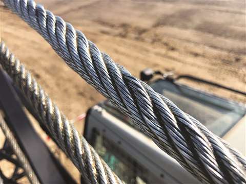
overhead crane wire rope changing procedure made in china

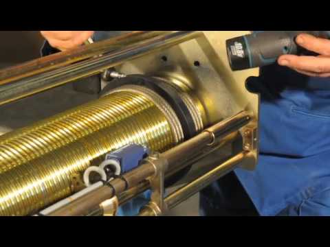
Single girder overhead travelling crane on the rope guide, also known as rope row device, is a relatively simple damage to the attachment. However, many customers do not know how to replace the rope guide. This article briefly introduced the replacement guide rope device approach and process, for your reference.
Single girder overhead travelling crane replacement guide rope device is necessary with matching. Some manufacturers produce can not use the traditional rope guide. Please pay attention to communicate with us when you buy. When replacing the rope guide, should first cut off the power, remove the wire rope. After removing the hexagonal screw of the rope guide, you can take down the rope guide along the wire rope. During this period, it is necessary to pay attention to the wire rope into the rope groove before installing the rope guide, so that the wire rope does not enter the groove, there may again crush the rope guide.
First remove the fixed screws fixed in the rope guide; open the rope guide, the block in the rope guide on the side facing outward, the rope guide into the; wire rope head into the rope guide, adjust the rope guide, straighten out the winding order of the wire rope; wire rope head into the fixed pile, wedge it with iron wedge; fixed rope guide, install all the fixed screws of the rope guide; start, adjust the rope guide. This is to ensure that the upper and lower rope guide can accurately cut off the fire source, do not let the wire rope relax the good position; single girder overhead crane guide rope device device is simple, the device is strong.
Rope diameter is specified by the user and is generally given in the equipment manufacturer’s instruction manual accompanying the machine on which the rope is to be used.
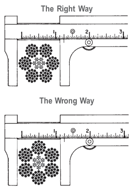
Rope diameters are determined by measuring the circle that just touches the extreme outer limits of the strands— that is, the greatest dimension that can be measured with a pair of parallel-jawed calipers or machinist’s caliper square. A mistake could be made by measuring the smaller dimension.
The right way to unreel.To unreel wire rope from a heavy reel, place a shaft through the center and jack up the reel far enough to clear the floor and revolve easily. One person holds the end of the rope and walks a straight line away from the reel, taking the wire rope off the top of the reel. A second person regulates the speed of the turning reel by holding a wood block against the flange as a brake, taking care to keep slack from developing on the reel, as this can easily cause a kink in the rope. Lightweight reels can be properly unreeled using a vertical shaft; the same care should be taken to keep the rope taut.
The wrong way to unreel.If a reel of wire rope is laid on its flange with its axis vertical to the floor and the rope unreeled by throwing off the turns, spirals will occur and kinks are likely to form in the rope. Wire rope always should be handled in a way that neither twists nor unlays it. If handled in a careless manner, reverse bends and kinks can easily occur.
The right way to uncoil.There is only one correct way to uncoil wire rope. One person must hold the end of the rope while a second person rolls the coil along the floor, backing away. The rope is allowed to uncoil naturally with the lay, without spiraling or twisting. Always uncoil wire rope as shown.
The wrong way to uncoil.If a coil of wire rope is laid flat on the floor and uncoiled by pulling it straight off, spirals will occur and kinking is likely. Torsions are put into the rope by every loop that is pulled off, and the rope becomes twisted and unmanageable. Also, wire rope cannot be uncoiled like hemp rope. Pulling one end through the middle of the coil will only result in kinking.
Great stress has been placed on the care that should be taken to avoid kinks in wire rope. Kinks are places where the rope has been unintentionally bent to a permanent set. This happens where loops are pulled through by tension on the rope until the diameter of the loop is only a few inches. They also are caused by bending a rope around a sheave having too severe a radius. Wires in the strands at the kink are permanently damagedand will not give normal service, even after apparent “re-straightening.”
When wire rope is wound onto a sheave or drum, it should bend in the manner in which it was originally wound. This will avoid causing a reverse bend in the rope. Always wind wire rope from the top of the one reel onto the top of the other.Also acceptable, but less so, is re-reeling from the bottom of one reel to the bottom of another. Re-reeling also may be done with reels having their shafts vertical, but extreme care must be taken to ensure that the rope always remains taut. It should never be allowed to drop below the lower flange of the reel. A reel resting on the floor with its axis horizontal may also be rolled along the floor to unreel the rope.
Wire rope should be attached at the correct location on a flat or smooth-faced drum, so that the rope will spool evenly, with the turns lying snugly against each other in even layers. If wire rope is wound on a smooth-face drum in the wrong direction, the turns in the first layer of rope will tend to spread apart on the drum. This results in the second layer of rope wedging between the open coils, crushing and flattening the rope as successive layers are spooled.
A simple method of determining how a wire rope should be started on a drum. The observer stands behind the drum, with the rope coming towards him. Using the right hand for right-lay wire rope, and the left hand for left lay wire rope, the clenched fist denotes the drum, the extended index finger the oncoming rope.
Clips are usually spaced about six wire rope diameters apart to give adequate holding power. They should be tightened before the rope is placed under tension. After the load is placed on the rope, tighten the clips again to take care of any lessening in rope diameter caused by tension of the load. A wire rope thimble should be used in the eye of the loop to prevent kinking.
U-bolt Clips.There is only one correct method for attaching U-bolt clips to wire rope ends, as shown in TheRightWayimage below. The base of the clip bears on the live end of the rope; the “U” of the bolt bears on the dead end.
Compare this with the incorrect methods. Five of the six clips shown are incorrectly attached—only the center clip in the top view is correct. When the “U” of the clip bears on the live end of the rope, there is a possibility of the rope being cut or kinked, with subsequent failure.
Proper seizing and cutting operations are not difficult to perform, and they ensure that the wire rope will meet the user’s performance expectations. Proper seizings must be applied on both sides of the place where the cut is to be made. In a wire rope, carelessly or inadequately seized ends may become distorted and flattened, and the strands may loosen. Subsequently, when the rope is operated, there may be an uneven distribution of loads to the strands; a condition that will significantly shorten the life of the rope.
Either of the following seizing methods is acceptable. Method No. 1 is usually used on wire ropes over one inch in diameter. Method No. 2 applies to ropes one inch and under.
Method No. 1: Place one end of the seizing wire in the valley between two strands. Then turn its long end at right angles to the rope and closely and tightly wind the wire back over itself and the rope until the proper length of seizing has been applied. Twist the two ends of the wire together, and by alternately pulling and twisting, draw the seizing tight.
The Seizing Wire. The seizing wire should be soft or annealed wire or strand. Seizing wire diameter and the length of the seize will depend on the diameter of the wire rope. The length of the seizing should never be less than the diameter of the rope being seized.
Proper end seizing while cutting and installing, particularly on rotation-resistant ropes, is critical. Failure to adhere to simple precautionary measures may cause core slippage and loose strands, resulting in serious rope damage. Refer to the table below ("Suggested Seizing Wire Diameters") for established guidelines. If core protrusion occurs beyond the outer strands, or core retraction within the outer strands, cut the rope flush to allow for proper seizing of both the core and outer strands.
The majority of wire rope problems occurring during operation actually begin during installation, when the rope is at its greatest risk of being damaged. Proper installation procedures are vital in the protection and performance of wire rope products.
Until the rope is installed it should be stored on a rack, pallet or reel stand in a dry, well-ventilated storage shed or building. Tightly sealed and unheated structures should be avoided as condensation between rope strands may occur and cause corrosion problems. If site conditions demand outside storage, cover the rope with waterproof material and place the reel or coil on a support platform to keep it from coming directly in contact with the ground.
While lubrication is applied during the manufacturing process, the wire rope must still be protected by additional lubrication once it is installed. Lubricants will dry out over a period of time and corrosion from the elements will occur unless measures are taken to prevent this from happening. When the machine becomes idle for a period of time, apply a protective coating of lubricant to the wire rope. Moisture (dew, rain, and snow) trapped between strands and wires will create corrosion if the rope is unprotected. Also apply lubricant to each layer of wire rope on a drum because moisture trapped between layers will increase the likelihood of corrosion.
Always use the nominal diameter as specified by the equipment manufacturer. Using a smaller diameter rope will cause increased stresses on the rope and the probability of a critical failure is increased if the rated breaking strength does not match that of the specified diameter. Using a larger diameter rope leads to shorter service life as the rope is pinched in the sheave and drum grooves which were originally designed for a smaller diameter rope. Just as using a different diameter rope can create performance problems, so can the use of an excessively undersized or oversized rope.
Measure the wire rope using a parallel-jawed caliper as discussed in Measuring Rope Diameter at the top of this page. If the rope is the wrong size or outside the recommended tolerance, return the rope to the wire rope supplier. It is never recommended nor permitted by federal standards to operate cranes with the incorrect rope diameter. Doing so will affect the safety factor or reduce service life and damage the sheaves and drum. Note that in a grooved drum application, the pitch of the groove may be designed for the rope’s nominal diameter and not the actual diameter as permitted by federal standards.
Wire rope can be permanently damaged by improper unreeling or uncoiling practices. The majority of wire rope performance problems start here.Improper unreeling practices lead to premature rope replacement, hoisting problems and rope failure.
Place the payout reel as far away from the boom tip as is practical, moving away from the crane chassis. Never place the payout reel closer to the crane chassis than the boom point sheave. Doing so may introduce a reverse bend into the rope and cause spooling problems. Follow the guidelines highlighted under Unreeling and Uncoiling and Drum Winding. Take care to determine whether the wire rope will wind over or under the drum before proceeding. If the wire rope supplier secured the end of the rope to the reel by driving a nail through the strands, ask that in the future a U-bolt or other nondestructive tie-down method be used; nails used in this manner damage the rope.
Take extra precaution when installing lang lay, rotation-resistant, flattened strand or compacted ropes. Loss of twist must be avoided to prevent the strands from becoming loosened, causing looped wire problems.
The end of the rope must be securely and evenly attached to the drum anchorage point by the method recommended by the equipment manufacturer. Depending on the crane’s regulatory requirements, at least two to three wraps must remain on the drum as dead wraps when the rope is unwound during normal operations. Locate the dead end rope anchorage point on the drum in relation to the direction of the lay of the rope. Do not use an anchorage point that does not correspond with the rope lay. Mismatching rope lay and anchorage point will cause the wraps to spread apart from each other and allow the rope to cross over on the drum. Very gappy winding will occur resulting in crushing damage in multilayer applications.
Back tension must be continually applied to the payout reel and the crewman installing the rope must proceed at a slow and steady pace whether the drum is smooth or grooved.Regardless of the benefits of a grooved drum, tension must be applied to ensure proper spooling. An improperly installed rope on a grooved drum will wear just as quickly as an improperly installed rope on a smooth drum. If a wire rope is poorly wound and as a result jumps the grooves, it will be crushed and cut under operating load conditions where it crosses the grooves.
Every wrap on the first or foundation layer must be installed very tightly and be without gaps. Careless winding results in poor spooling and will eventually lead to short service life. The following layers of rope must lay in the grooves formed between adjacent turns of the preceding layer of rope. If any type of overwind or cross-winding occurs at this stage of installation and is not corrected immediately, poor spooling and crushing damage will occur.
On a multilayer spooling drum be sure that the last layer remains at least two rope diameters below the drum flange top. Do not use a longer length than is required because the excess wire rope will cause unnecessary crushing and may jump the flange. Loose wraps that occur at any time must be corrected immediately to prevent catastrophic rope failure.
The use of a mallet is acceptable to ensure tight wraps, however a steel-faced mallet should be covered with plastic or rubber to prevent damage to the rope wires and strands.
Rotation-resistant ropes of all constructions require extra care in handling to prevent rope damage during installation. The lay length of a rotation-resistant rope must not be disturbed during the various stages of installation. By introducing twist or torque into the rope, core slippage may occur—the outer strands become shorter in length, the core slips and protrudes from the rope. In this condition the outer strands become over- loaded because the core is no longer taking its designed share of the load. Conversely, when torque is removed from a rotation-resistant rope core slippage can also occur. The outer strands become longer and the inner layers or core become overloaded, reducing service life and causing rope failure.
The plain end of a wire rope must be properly secured. If the entire cross section of the rope is not firmly secured, core slippage may occur, causing the core to pull inside the rope’s end and allowing it to protrude elsewhere, either through the outer strands (popped core) or out the other end of the line. The outer layer of the outside strands may also become overloaded as there is no complete core-to-strand support.
Secure the ends of the rope with either seizing or welding methods as recommended under Seizing Wire Rope. It is imperative that the ends be held together tightly and uniformly throughout the entire installation procedure, including attaching the end through the wedge socket and the drum dead end wedge
When installing a new line, connect the old line to the new line by using a swivel-equipped cable snake or Chinese finger securely attached to the rope ends. The connection between the ropes during change-out must be very strong and prevent torque from the old rope being transferred into the new rope.Welding ropes together or using a cable snake without the benefit of a swivel increases the likelihood of introducing torque into the new rope. A swivel-equipped cable snake is not as easy as welding the ropes, but this procedure can be mastered with a little patience and practice.

Radically redesigned with never-before-seen features – both inside and out – the S-series will set the standard in lifting for years to come. The newly designed structure includes next-generation features such as off-set reeving, stepless hoisting movement and synthetic rope. The tilted rope drum enables more direct rope angles to decrease the wear and tear of reeving components. And offset reeving means more balanced wheel loads for less stress on the crane structure.
The evolutionary synthetic rope is durable but light and doesn’t require lubrication. The rope also features a strong, symmetric structure for less rope defects and safer handling. Rope angle measurement allows for the use of Smart Features including Hook Centering, Snag Prevention and Follow Me.

Buying new crane ropes is a detailed and thorough process. While it may be time-consuming, wire rope replacement prioritizes safety for your workers, minimizes downtime on a jobsite, maximizes the lifespan of the crane and avoids the costly and time-consuming process of getting correct rope onsite and respooling your crane.
Sometimes, it can seem like the wire rope buying process is overly complicated. This is done on purpose to avoid as many issues as possible when the new rope is installed. The reason for that is so buyers avoid putting the wrong types of ropes on cranes and unnecessarily increasing the risk of injuries to workers or damage to loads being lifted. The processes are to make sure to prevent that added risk and put the correct rope on the correct machine, per Original Equipment Manufacturer (OEM) specifications.
Wire rope specialists ask these questions to understand your circumstances and what your needs are. With this information, they are better prepared to get the absolute correct rope.
Most of the time, the customer should have access to their crane’s operations manual that will show what rope diameter and length is specified. The customer may have to measure or come up with his own calculations on length. The crane manufacturer is going to make a specific drum for that specific type of wire rope.
The rope has to be specific to the lagging of the drum for that machine, which is why there are multiple variations for each size of wire rope because each kind is specific to the type of crane, and it shouldn’t be substituted. Mazzella will only install the rope that is the correct brand and tolerance on a particular crane.
Ordering the correct crane rope will prevent crane rope damage. The wrong rope could cause damage to the equipment, and at worst, boom failure. On the less severe side, you will have bad performance or it might not work at all. You could have twist and/or spooling issues. That could lead to the crane failing altogether, which creates downtime as you wait for the correct wire rope to be ordered/delivered and installed.
Many crane owners are working for somebody else when they’re doing jobs, so if the rope doesn’t work, they’re paying for work that is not getting done and falling behind schedule.
On the more severe side, you could total your crane and/or irreparably damage the load being lifted if you use the wrong wire rope. In the worst-case scenario, using the incorrect rope could result in severe injury and/or the loss of life.
Sometimes, customers assume that there’s a one-size-fits-all replacement, that if it’s a non-rotating rope, it should work on every application. There’s a lot of misinformation on what will work and what won’t work. With our experience and access to all brands of wire rope, Mazzella guarantees we can get you the right rope for your cranes. If Mazzella isn’t comfortable with the project, we won’t supply the wire rope.
If the wrong wire rope is ordered and delivered, it could be hours or days before the correct rope is on location. Especially with a lot of the larger cranes, manufacturers are shipping model-specific ropes all over the country, and depending on location and money, that could cause delays on your jobsite.
With our large inventory of rope, Mazzella can have a new spool of wire on a truck and out for delivery in a matter of hours. Avoid the pitfalls of ordering the wrong crane rope and you’ll have a new spool of wire rope on its way. Once the order process is done, what can your company do to prepare for delivery and installation?
It is a good idea to give management the proper notice of when the installer will be on-site, have the necessary technicians on-site to help the installer with the rope replacement and make sure the installer/technicians have a clear working space.
There’s a lot of downtime associated with making a mistake in the preparation process, so the more prepared you can be for the install, the better. You don’t want a situation where your crane is inactive because of an oversight or completely avoidable situation.
Also, Mazzella recommends you measure your sheaves with a sheave gauge. A sheave gauge will help you measure the wear of the root, the amount of wear on the groove wall and the diameter of the wire rope.
After ordering the correct rope and having the requisite space and approval for installation, how long will it take to remove and replace the old rope when the technician, assistants and supplies arrive onsite? For some small cranes, the timeframe could be as little as 45 minutes, but for larger cranes, removing the old rope and installing the new one could be a several-hour process.
There’s a lot of factors that go into a successful crane rope installation. The most important thing is the quicker your supplier responds to your order and gets a rope on location, the quicker that rope gets installed properly, saving time and money. Downtime is the key, and it could cost companies tens of thousands of dollars per day if their crane(s) are inoperable.
Once a new crane rope is installed, a break-in period or tension period is recommended to make sure everything is performing correctly, and help you avoid shock-loading the newly installed wire rope. The break-in period is recommended because installation and spooling equipment are not going to put adequate tension on the rope. A break-in period consists of putting a low percentage of the working load limit weight on the rope for several lift cycles, and running the blocks up to the boom length (working height) and back down. For the most specific guidelines on the breaking-in process for your new wire rope, refer to the manufacturer’s recommendations.
If a brand-new wire rope on a crane is not broken in properly before lifting a large load, it potentially could damage the rope and render useless the equipment that was just installed on your machine.
When Mazzella fulfills a crane ropes order, it is not just about the sale and the bottom line. While we’re in the business of selling crane ropes, we’re also in the business of building relationships and trust. We are committed to making sure you get the correct products for the right applications.
Crane rope issues don’t just happen 9-to-5 during the normal work week. They happen Friday nights, holidays, weekends and early mornings. They’re always on the clock, and it is just about being honest with the customer and letting them know, they type of rope that is required. That honesty and trust is of utmost importance for the safety of your workers and the proper maintenance of your cranes.
Mazzella has one of the largest crane ropes inventories in the United States. The company provides wire rope assemblies and manufactures bridge cables, crane cables, steel mill cables and thousands of OEM assemblies in sizes from ¼ to 3-inch diameter and 9 to 52 millimeter diameter, domestic and non-domestic and in stock and ready for same or next-day shipment.

Utilize method of the present invention that the steel rope of the 450t driving of big section steel works is changed, concrete method of operation be described in conjunction with Fig. 1 and Fig. 2:
1, with 80t auxiliary hook 2, hangs a pair of ¢ 50mm*8000 steel rope, and utilize the shackle of 4 16t, hang main hook portal frame 7, remove master file spacing 1;
2, the master file 8 200~300mm that descends, after tear 4 bearing pins of steel rope fixed end bracket on the portal frame movable pulley open, the long rope made of hemp with 4 ¢ 14mm*15000 draws again, 4 steel ropes in general who has surrendered termination are moved ground under the master file, cut off the steel rope on the bracket.
Steel rope at first should be the excision of the head sections of steel rope when connecting, because this section may be in installation process, is squeezed or beats, and causes the loosening or distortion of steel rope head, can cause influence of low quality to the welding of steel rope,
Secondly should in the 300mm scope of welding, use oxy-acetylene flame and add the blanching burning, grease in the steel rope is cleared up, can guarantee that like this steel rope removes oil contamination when welding process, and can suitably reduce the degree of hardening of steel rope steel wire, guarantee that the steel rope welded joint is not fractureed in the replacing process.Before the welding, the steel rope of welding must be soaked, cleaned 15 minutes with acetone simultaneously, be used to clear up impurity such as the greasy dirt of welded-joint and oxidizing substance, guarantee the welded joint of steel rope effectively.
As shown in Figure 1, roll tightly with rolling hoop part 2, unclamp steel rope (totally 6 strands), again the single steel wire of new steel rope spare 1 with old steel rope spare 3 is blended together, tie admittedly, can weld with thin wire at 300mm place, the termination of new and old steel rope.
The welding material of wireline adapter adopts weldability good, and the cooresponding J50 welding wire of intensity and steel rope begins to carry out fusion at the wireline adapter position with brazing torch then, treat that the molten bath forms the back and adds welding wire, simultaneously, slowly rotate steel rope, until joint bevel is filled up.
After having welded, beaing the wireline adapter position with hand hammer immediately can be consistent with the steel rope external diameter, in case cause screens in the replacing process, can suitably increase the metal compaction of welded joint, increases the tensile strength of steel rope.
After the process of whole operation finished, this moment, the weld bond place can"t adopt water-cooled or pressurized air chilling, in order to avoid cause the brittle failure in the steel rope replacing process, must allow the steel rope natural cooling, can change operation.
2, steel rope personality card under the reel and 1t cucurbit are hung, remove steel rope pressing plate on the reel then, fag end 6 is transferred, with the rope made of hemp fag end is held, the ground staff holds the rope made of hemp;
吊,搬送する大型天井クレーン等の分野で利用される。Description: TECHNICAL FIELD The present invention relates to a method for replacing a wire rope of a crane, and more particularly, to efficiently use an old wire rope wound around a hoisting drum installed on a crane. The present invention relates to a method of replacing a new wire rope with an old wire rope which can be automatically wound on the ground. This is used in the field of large overhead cranes that suspend and transport heavy objects such as coiled steel plates and ingots.
えたフックブロック8を懸吊している。A wire rope wound around a hoisting drum such as a large overhead crane installed in a rolling mill of a steel mill is, for example,
いう)までも解く。In such an overhead crane, replacement work of the old wire rope 6 has been conventionally performed as follows. As shown in FIG. 9, first, the hoisting drum 5 is rotated in the hoisting direction (the direction opposite to the arrow 42), and the hoisting drum 5 is rotated.
The views of the old wire rope 6 are sequentially solved from the winding grooves 5c and 5d in the left-right inverted spiral shape engraved on the hook block 8, and the hook block 8 is lowered onto the support base 9 placed on the ground and firmly mounted.
Remove one end 6a (see FIG. 10) of the old wire rope 6 that is hung on the floor, tie the end 6a with a cremona rope (not shown), and lower it to the ground. Then, the Cremona rope is removed, and one end of the new wire rope 10 wound around the feeding means 11 arranged in advance on the ground and one end 6a of the old wire rope 6 are connected by a connecting fitting (not shown) or the like. . After that, the hoisting drum 5 is rotated in the hoisting direction 42, and the new wire rope 10 is started to be pulled up to the hoisting drum 5, while the old wire rope 6 is wound about three times around the winding groove 5d of the hoisting drum 5. Let This is to secure a frictional force such that the old wire rope 6 and the new wire rope 10 do not slip on the hoisting drum 5 when the hoisting drum 5 is subsequently rotated in the hoisting direction 42 and the old wire rope 6 is paid out. This is to keep it. After that, the other end 6b (the first end) of the old wire rope 6 hooked on the fixture 5b provided on the other end of the hoisting drum 5 (first
戻し、再度、上記と同じ作業を繰り返す。The other end of the old wire rope 6 is tied with a cremona rope or the like, and in this state, the hoisting drum 5 is further rotated in the hoisting direction 42, while the other end is guided so as not to bounce, while the club 4 is being guided. The old wire rope 6 is let out to the ground through the handrail 4a, and the worker waiting on the ground bundles the old wire rope 6 in a ring shape. During this operation, the old wire rope 6 wound around the winding drum 5 moves in the direction of the arrow 44 along the spiral winding groove 5d. When the wound portion of the old wire rope 6 reaches the central position approaching the winding groove 5c of the reverse spiral, there is no winding allowance for the old wire rope 6 to move, and at that time, the rotation of the hoisting drum 5 To stop. The old wire rope 6 in the wound state is loosened on the hoisting drum 5 by the operator"s manual work so as to float from the winding groove 5d, and the old wire rope 6 is left as it is at the left end of the winding groove 5d where the fixture 5b is located. Return to and repeat the same operation as above.
了される。When the connection between the new wire rope 10 and the old wire rope 6 reaches the upper position 43 of the hoist drum 5 by sequentially tracing the hook block 8 and the upper sheave 7 (see FIG. 10) by such work. The rotation of the hoisting drum 5 is stopped, the connecting portion is disconnected, and one end of the new wire rope 10 is hooked on the fixture 5b of the hoisting drum 5. The other end 6b of the old wire rope 6
Is tied with a cremona rope, and it is lowered to the ground, and the last part of the old wire rope 6 is also bundled into a ring on the ground. On the other hand, the other end of the new wire rope 10 is removed from the feeding means 11, the other end is tied with a cremona rope or the like and pulled up onto the club 4, and the other end is hooked on the fixture 5a of the hoisting drum 5. After the hoisting drum 5 is rotated in the hoisting direction 42 and the new wire rope 10 is additionally wound at both ends of the hoisting drum 5, the hoisting drum 5 is further rotated in the hoisting direction, whereby the new wire rope 10 Is wound around the hoisting drum 5, and the hook block 8 rises. In this way, the replacement work of the old wire rope 6 and the new wire rope 10 is completed.
非常に煩わしいものであった。In such a conventional replacement method, while rotating the hoisting drum 5 at the high position of the ceiling part, the old wire rope 6 is unwound to the ground, while the unwound old wire rope 6 is bundled by the operator on the ground. It was being done. For large overhead cranes, the diameter of the wire rope used for them is as large as 25 mm to 40 mm, and the work of bundling them is not very efficient because it requires a lot of manpower and is a very heavy work. In addition, it is necessary for the bundling operator and the crane operator to work while constantly signaling each other.
提案した。For this reason, the applicant of the present invention, after fixing the hook block to the ground, connects one end of the old wire rope to the new wire rope and connects the other end of the old wire rope to the winding means separately prepared. JP-A-63-17792 proposes a method for replacing the wire rope of a crane, in which the old wire rope is wound up only by the pulling force driven by the winding means without driving the hoisting drum. did.
善が強く望まれていた。In the above method, the pulling force of the winding means arranged on the ground acts on the entire wire rope, and by extension, the old wire rope in the portion stretched between the upper sheave and the hook block is also directly affected. It was necessary to fix the hook block particularly firmly. In addition, the strength of the winding means must be increased in order to obtain a sufficient tensile force, and the drive source requires considerably large power. This is even more so when the wire rope is thick and heavy, which causes problems such as an increase in the size of the device and an increase in cost, and a restriction on the work space. Further, since a large tension acts on the wire rope, the connection portion between the new wire rope and the old wire rope may be disconnected, and improvement of the work has been strongly desired.
ープ取替方法を提供することである。The present invention has been made in consideration of such circumstances, and an object of the present invention is not to require a compact and large space, to keep a large tension applied to the wire rope at all times, and to make the wire rope thick. It is an object of the present invention to provide a method for replacing a wire rope of a crane, in which the safety of the replacement work is highly secured and the wire rope can be efficiently replaced with a new wire rope.
けるワイヤロープの取替方法に適用される。INDUSTRIAL APPLICABILITY The present invention is applied to a method for replacing a wire rope in a crane equipped with a hoisting drum for winding a wire rope, which is installed on a truck traveling on a rail.
It is lowered to the ground by rotating in the winding direction (the direction opposite to the arrow 42), and is unwound from the hoisting drum 5 to the old winding of the old wire rope 6. The one end 6a of the old wire rope 6 is removed from one end of the hoisting drum 5, and the one end 6a of the old wire rope 6 is lowered to the ground and connected to one end of the new wire rope 10 wound around the feeding means 11. Next, the hoisting drum 5 is rotated in the hoisting direction 42, and the old wire rope 6 is wound around the hoisting drum 5 a predetermined number of times. Remove the other end 6b. Rotate the hoisting drum 5 further in the hoisting direction 42,
The new wire rope 10 is started to be pulled up to the hoisting drum 5, and the other end 6b of the old wire rope 6 is fed to the ground. The other end 6b of the old wire rope 6 is connected to the rotary table 17 arranged on the ground, and the winding direction of the winding drum 5 thereafter is increased.
The old wire rope 6 is fed to the ground by rotating the old wire rope 6 and the rotation speed of the rotary table 17 is adjusted so that the old wire rope 6 has a desired winding diameter without tension. That is, the ropes 6 are stacked in a ring shape and bundled.
うにしてもよい。Further, referring to FIG. 5, the iron cage 18 having a cylindrical iron cage 18a surrounded by the old wire ropes 6 which are stacked in a ring shape is detachably provided on the rotary table 17 and is fed to the ground. The old wire rope 6 may be bundled in a ring shape by the rotation of the rotary table 17 while preventing the winding wire of the old wire rope 6 from being disturbed by the cylindrical basket portion 18a.
While contacting the old wire rope 6 that has been fed to the ground through the upper opening of 8c, to the ring-shaped pipe material that is located at the boundary between the truncated cone-shaped groin portion 18b and the truncated cone-shaped small groin portion 18c. Alternatively, the old wire ropes 6 may be stacked and bundled in a ring shape by the rotation of the rotary table 17.
とした巻き取りを実現することができる。According to the present invention, one end of an old wire rope removed from a hoisting drum is connected to a new wire rope, and the old wire rope is wound around the hoisting drum a predetermined number of times, and then the hoisting drum is rotated in a hoisting direction. Since the other end of the old wire rope is drawn to the ground while being made to move, the old wire rope can be reliably drawn without slipping, and the new wire rope can be wound around the hoisting drum. Then, the old wire rope is extended to the other side by the rotation of the hoisting drum in the winding direction and the rotation speed of the rotary table is adjusted to connect the old wire rope to the movement of the rotary table arranged on the ground. Since the wire rope is wound, it is possible to efficiently stack the old wire ropes in a loop so that the old wire ropes have a desired winding diameter without exerting a large tension on the wire ropes. That is, if the rotation speed of the rotary table is increased, the winding can be made thinner, and if the winding is tightened too much, it can be slowed down and corrected, or a large bunch of wheels can be stacked. Orderly winding can be achieved with any diameter.
ないものとしておくことができる。If a carcass with a cylindrical cage that surrounds the old wire ropes that are bundled in a ring shape is detachably attached to the rotating table, the disorder of the winding appearance of the old wire ropes that have been fed to the ground will be cylindrical. Part is prevented by
The old wire rope can be smoothly looped and bundled by rotating the rotary table. For example, if the old wire rope suddenly jumps out, the cylindrical cage prevents it. Further, even if the ring-shaped bundle is greatly tilted, it is prevented from deviating from the turntable. Of course, the old wire ropes can be bundled compactly to facilitate the subsequent treatment, and the winding means can be made to require no space.
しておきたい場合に都合がよい。By forming a truncated cone-shaped basket on the upper part of the cylindrical basket, the old wire rope that is fed to the ground is brought into contact with the inner surface of the truncated cone and the rotary table rotates to form a ring shape. Can be stacked and bundled. For example, even if a situation occurs in which the old wire rope is excessively shaken by centrifugal force or the like due to the rotation of the turntable, the wound form after that is not greatly impaired. This is convenient when it is desired to keep the winding diameter large.
同心状の巻取り姿となるよう誘導することができる。A small frustoconical small squirrel cage is formed in the upper part of the frustoconical squirrel cage, and the old wire rope that is fed to the ground through the upper opening of the frustoconical small squirrel cage is cut into a truncated cone shape. The old wire ropes can be looped and bundled by rotating the rotary table by contacting them in a ring-shaped pipe shape located at the boundary between the pallet cage and the truncated cone small pallet cage. Not only does the frustoconical small squirrel cage guide the movement of the old wire rope to suppress unnecessary fluctuations, but the frustoconical small squirrel cage is narrower toward the top to allow the old wire rope to be thin. It is possible to prevent the body from jumping out of the body and guide it to have a concentric winding shape.
等の重量物を懸吊,搬送するものである。The wire rope replacement method shown in the present embodiment efficiently uses a thick and rigid old wire rope wound around the hoisting drum of a crane by using a vertically-shaped winding means that is compactly formed. It is a new wire rope that can be replaced and the old wire rope can be wound and bundled without requiring a large amount of power. The crane to which this wire rope replacement method is applied is, for example, a large overhead crane 1 as shown in FIG.
ーブ7を介してフックブロック8を懸吊している。As shown in FIG. 1, rails 3a, 3a are laid on a girder 3 of the overhead crane 1, and a club 4 as a truck moving on the rails 3a is rotated by a drive source (not shown). The hoisting drum 5 is stationary. The winding drum 5 is provided with spiral winding grooves 5c, 5d in the opposite direction on the left and right, and both ends 6a of the old wire rope 6 wound along the winding grooves 5c, 5d. As shown in FIG. 10, the wires 6b are hooked at both ends of the hoisting drum 5, and the wire ropes 6 thereof are hooked via the upper sheave 7 arranged at the lower part of the hoisting drum 5. Is suspended.
ブブロック(図示省略)に軸支されている。The hook block 8 pivotally supports four movable pulleys 8A, 8A, and a load hanging hook 8a (see FIG. 1) is hung at the bottom thereof. That is, the fixtures 5a and 5b for attaching the wire rope are provided at both ends of the hoisting drum 5, and the wire rope in which the hook block 8 is suspended via the upper sheave 7 on the fixtures 5a and 5b. One end 6a and the other end 6b of 6,
を巻き取る巻取手段12とにより構成される。As shown in FIG. 1, the wire rope replacement device has a support base 9 placed on the ground for mounting the hook block 8 and one end 6a of the old wire rope 6 removed from the hoisting drum 5. A feeding means for feeding the new wire rope 10 to be connected
9上でも充分な安定を得ることができる。The support base 9 is a base with four legs having a mounting surface on the top, and is simple enough for an operator to easily carry. As will be described later, since the old wire rope 6 to be replaced is unwound by the hoisting drum 5, a large external force does not act on the hook block 8 via the old wire rope 6 during the replacement work. It is possible to obtain sufficient stability even on a simple support base 9.
を、順次繰り出すことができるようになっている。The feeding means 11 has a rotatable disc (not shown) inside an annular base 14 having a plurality of shelves 13 arranged on the outer periphery thereof, and a core member protruding in the center of the disc. A new wire rope 10 is coiled around and mounted on a disk around 15
と共に駆動源19により回転されるようになっている。The winding means 12 is, as shown in FIGS. 4 and 5, a vertical guide shaft 16 for guiding the old wire rope 6 unwound from the winding drum 5 to be wound up.
In order to enclose the horizontal rotary table 17 that rotates with the guide shaft 16 to receive the old wire rope 6 in a ring shape, and the old wire rope 6 that is detachably provided on the rotary table 17 and is bundled in a ring shape. And a vertical frame 18 to be arranged, and the rotary table 17 is provided with a guide shaft 16
けている。The iron cage 18 is a ring-shaped pipe material 24 arranged laterally so as to surround the outer circumference of the old wire rope to be wound up.
Is provided with a cylindrical cross-shaped cage 18a, which is a combination of the pipe members 25 arranged in the vertical direction so as to intersect with each other, and on the upper part thereof, a two-pointed truncated conical cross-shaped cage for introducing and guiding an old wire rope. The portion 18b is provided with a truncated cone small cross-section basket 18c.
けられている。By the driving force of the vertical geared motor 19 described above, the guide shaft 16 integrated with the rotary table 17 and the cross cage 18 are rotated, and the old wire rope introduced from the upper opening of the truncated cone small cross cage 18c. 6 (see FIG. 1) can be bundled around the guide shaft 16 in a ring shape. The angle members 30 are radially arranged on the rotary table 17 so that a small space is formed under the bundled old wire ropes so that the bundled old wire ropes can be easily taken out. Also,
Has only to have an output enough to stack and bundle the fed old wire ropes 6, and the output is relatively small such as 3.7 kw. Cross cage 18 and rotary table
The rotation speed of the rotary table 17 can be adjusted according to the descending speed of the old wire rope 6 fed out from the table, so that the old wire rope 6 can be bundled without wasting space, and the old wire rope 6 can be bundled by changing the rotation speed. The ring diameter can be changed arbitrarily each time. Further, the operator can carry the operation box 33 with the frequency meter and operate it in any safe place.
に説明する。The replacement work of the old wire rope 6 and the new wire rope 10 by the wire rope replacement device thus configured will be described below.
置した支持台9上にフックブロック8を載置する。(A) First, as shown in FIG. 1, the old wire rope 6 is unwound by rotating the hoisting drum 5 in the lowering direction (the direction opposite to the arrow 42), and the hook block 8
端に、連結金具(図示せず)等で接続する。(C) The one end 6a of the old wire rope 6 is removed from the fixture 5a of the hoisting drum 5, and the one end 6a is tied with a cremona rope (not shown) or the like and manually lowered to the ground. And after removing the cremona rope, one end 6a
るためである。(D) Next, as shown in FIG. 2, the hoisting drum 5 is rotated in the hoisting direction 42, and the old wire rope 6 is wound around the winding groove 5d of the hoisting drum 5 a predetermined number of times, for example, about three times. After that, the other end 6b of the old wire rope 6 hooked on the fixture 5b of the hoisting drum 5 is removed. In addition, when the hoisting drum 5 is rotated, the above-described three times of winding do not cause the old wire rope 6 wound around the hoisting drum 5 to slip from the hoisting drum 5 and prevent the old wire rope 6 from winding. This is so that a desired frictional force can be exerted at the time of feeding and raising the new wire rope 10.
の下部に連繋,固定する。(E) The hoisting drum 5 is further rotated in the hoisting direction 42, and the new wire rope 10 is started to be pulled up to the hoisting drum 5, and the other end 6b of the old wire rope 6 is tied with the cremona rope. The handrail 4a of the club 4 shown in FIG. 1 is guided by a Cremona rope so that the end 6b does not bounce.
も、回転テーブル17から逸脱することが防止される。(F) If the winding means 12 is rotated by the drive source 19 while rotating the hoisting drum 5 in the hoisting direction 42, the old wire rope 6 is fed toward the ground by the rotational force of the hoisting drum 5. In this state, the old wire rope 6 can be wound inside the cage 18 by unwinding the old wire rope 6 to the ground and adjusting the rotation speed of the rotary table 17. That is, if the rotation is accelerated by the speed control of the rotary table 17, the winding can be thinned, and if the winding is tightened too much, the winding can be slowed to correct or a large ring is piled up. Orderly winding is realized. In this winding operation, the new wire rope 10 is unwound from the unwinding means 11 as much as the old wire rope 6 is wound up. As shown in the figure, if the guide shaft 16 is erected at the center of the rotary table 17, the winding state of the old wire rope 6 can be maintained at the center. Although the iron cage 18 may be omitted, if it is provided, the winding appearance of the old wire rope can be prevented from being disturbed. That is, even if the old wire rope 6 suddenly jumps out, the pipe material 25 of the cylindrical basket 18a blocks it.
溝5dに沿って固定具5b側へ逆戻りされる。(G) A winding groove in which the old wire rope 6 wound around the winding drum 5 is spirally engraved in the middle of this work.
The winding drum 5 is moved along the direction 5d in the direction of the arrow 44 to reach the end of the winding groove 5d at the substantially central position, so that the winding drum 5 is stopped from rotating. When the wire rope is thin and slightly light, the old wire rope 6 is loosened on the hoisting drum 5 by the operator"s manual work and floated from the winding groove 5d.
Return to the left end where the fixture 5b is located. If the wire rope is thick and heavy, the operator should remove part of the old wire rope 6 from the handrail 4a.
Loosen a little above. When the hoist drum 5 is further rotated in the same direction in a state where the old wire rope 6 is floated to the extent of causing slippage with the winding groove 5d, the old wire rope 6 is fixed along the winding groove 5d with the fixture 5b. It is returned to the side.
ねられる。(H) While repeating the above procedure, the operation of feeding the old wire rope 6 to the ground is performed by rotating the hoisting drum 5 in the winding direction, but the old wire rope 6 is not subjected to a strong tension, The old wire ropes 6 are looped and bundled on the turntable 17 so that the desired winding diameter is obtained.
Disconnect the connection. One end 6a of the old wire rope 6 is bound with a Cremona rope or the like, while one end of the new wire rope 10 is attached to the fixture 5b. One end 6a of the old wire rope 6 is gradually lowered to the ground by a worker on the club 4 using a cremona rope. At that time as well, the winding means 12 is rotated, and when all the old wire ropes 6 are bundled, the work of collecting the old wire ropes 6 is completed.
ックブロック8も上昇する。(J) Remove the fixed end of the new wire rope 10 from the feeding means 11, tie it with a cremona rope, and pull it all up on the club 4, and hook the other end on the fixture 5a of the hoisting drum 5. Rotate the hoisting drum 5 further and use the new wire rope 10
When the winding wire is wound around both ends of the hoisting drum 5 and further wound up, the new wire rope 10 is wound around the hoisting drum 5, and the hook block 8 also rises.
とは言うまでもない。In the winding operation performed in this manner, since the old wire rope 6 is unwound by the rotational force of the hoisting drum 5, a large tension based on the drive of the winding means 12 acts on the old wire rope 6 as in the conventional case. There is nothing to do. Therefore, disconnection of the connection between the old wire rope 6 and the new wire rope 10 is avoided. Further, since the force via the old wire rope 6 does not act on the hook block 8 as in the conventional case, the support base 9 can be relatively small, and the hook on the ground is not required. The block 8 can be easily supported. By the way, a cage
It goes without saying that if the 18 is removed from the rotary table 17, the wound old wire rope 6 can be easily taken out from the winding means 12.
生じても以後の巻取り姿を大きく損なうことはない。By the way, if the casket body 18 is provided with the truncated cone-shaped cage part 18b in the upper portion as shown in FIG. 5, the old wire rope 6 fed to the ground is brought into contact with the inner surface of the truncated cone-shaped casket part 18b. On the other hand, the rotary table 17 can be rotated and stacked in a ring shape. This is convenient when the winding diameter is often increased, as indicated by the dashed line. For example, even if a situation occurs in which the centrifugal force based on the rotation of the rotary table 17 acts excessively on the old wire rope 6 to cause it to be swung, it does not significantly impair the subsequent winding state.
滑な誘導が実現される。Further, when the truncated cone small cross basket 18c connected to the upper part of the truncated cone cross basket 18b is formed, the old wire which is fed to the ground through the upper opening of the truncated cone small cross basket 18c. While the rope 6 is in contact with the ring-shaped pipe material 24A located at the boundary between the frustoconical spatula portion 18b and the frustoconical spatula portion 18c, the old wire ropes 6 are bundled in a ring shape by the rotation of the rotary table 17. be able to. In this case, as shown by the chain double-dashed line, the inner ring surface of the pipe member 24A guides the movement of the old wire rope 6 and suppresses unnecessary wobbling of the old wire rope 6. Of course, the frustoconical small squirrel cage 18c becomes narrower as it goes upward, so that when the old wire rope is thin, it is prevented from jumping out of the squirrel cage 18 and a smooth concentric guidance is realized.
とすることができる。The winding means 12 does not require a particularly strong winding force as in the conventional case, and a rotating force for binding the old wire rope 6 fed out over the handrail 4a of the club 4 at its lower position to the rotary table 17. Just give it. Therefore, the vertical geared motor 19 serving as a drive source thereof can have a low output. Further, since the winding means 12 is hardly affected by the tension of the old wire rope 6, it is not necessary to fix it to the ground. Because of this, the old wire rope 6 can be made small together with the adoption of the cross cage 18, and the winding means 12 can be made more compact than the conventional one.
Even if the diameter of the old wire rope 6 is as thick as 40 mm and has high rigidity, the winding diameter in the carcass 18 can be reduced or increased, and the winding shape of the old wire rope 6 can be increased. The volume can be reduced.
パイプ材、42……巻き上げ方向。FIG. 1 is an overall configuration diagram of a wire rope replacement device used for carrying out the method of the present invention, FIG. 2 is a schematic diagram showing a tensioned state of the wire rope during replacement work, and FIG. FIG. 4 is a perspective view of the crane, FIG. 4 is a plan view of the winding means, and FIG.
6 is a perspective view of the operation box with a frequency meter, FIG. 7 is its internal circuit diagram, FIG. 8 is its external connection diagram, and FIG. 9 is a conventional wire rope. Replacement work diagram, No. 10
The figure is a schematic view showing a state in which the wire rope is stretched in a normal state of the crane. 1 ... Crane (overhead crane), 3a ... Rail, 4 ...
… Club (carriage), 5 …… Winding drum, 6 …… Old wire rope, 6a …… One end, 6b …… Other end, 8 …… Hook block, 10 …… New wire rope, 11 …… Feeding means, 17-Rotary table, 18-Case cage, 18a-Cylindrical cage section, 18b
A competent person must begin a visual inspection prior to each shift the equipment is used, which must be completed before or during that shift. The inspection must consist of observation of wire ropes (running and standing) that are likely to be in use during the shift for apparent deficiencies, including those listed in paragraph (a)(2) of this section. Untwisting (opening) of wire rope or booming down is not required as part of this inspection.
Significant distortion of the wire rope structure such as kinking, crushing, unstranding, birdcaging, signs of core failure or steel core protrusion between the outer strands.
In running wire ropes: Six randomly distributed broken wires in one rope lay or three broken wires in one strand in one rope lay, where a rope lay is the length along the rope in which one strand makes a complete revolution around the rope.
In rotation resistant ropes: Two randomly distributed broken wires in six rope diameters or four randomly distributed broken wires in 30 rope diameters.
In pendants or standing wire ropes: More than two broken wires in one rope lay located in rope beyond end connections and/or more than one broken wire in a rope lay located at an end connection.
If a deficiency in Category I (see paragraph (a)(2)(i) of this section) is identified, an immediate determination must be made by the competent person as to whether the deficiency constitutes a safety hazard. If the deficiency is determined to constitute a safety hazard, operations involving use of the wire rope in question must be prohibited until:
If the deficiency is localized, the problem is corrected by severing the wire rope in two; the undamaged portion may continue to be used. Joining lengths of wire rope by splicing is prohibited. If a rope is shortened under this paragraph, the employer must ensure that the drum will still have two wraps of wire when the load and/or boom is in its lowest position.
If a deficiency in Category II (see paragraph (a)(2)(ii) of this section) is identified, operations involving use of the wire rope in question must be prohibited until:
The employer complies with the wire rope manufacturer"s established criterion for removal from service or a different criterion that the wire rope manufacturer has approved in writing for that specific wire rope (see § 1926.1417),
If the deficiency is localized, the problem is corrected by severing the wire rope in two; the undamaged portion may continue to be used. Joining lengths of wire rope by splicing is prohibited. If a rope is shortened under this paragraph, the employer must ensure that the drum will still have two wraps of wire when the load and/or boom is in its lowest position.
If the deficiency (other than power line contact) is localized, the problem is corrected by severing the wire rope in two; the undamaged portion may continue to be used. Joining lengths of wire rope by splicing is prohibited. Repair of wire rope that contacted an energized power line is also prohibited. If a rope is shortened under this paragraph, the employer must ensure that the drum will still have two wraps of wire when the load and/or boom is in its lowest position.
Where a wire rope is required to be removed from service under this section, either the equipment (as a whole) or the hoist with that wire rope must be tagged-out, in accordance with § 1926.1417(f)(1), until the wire rope is repaired or replaced.
Wire ropes on equipment must not be used until an inspection under this paragraph demonstrates that no corrective action under paragraph (a)(4) of this section is required.
At least every 12 months, wire ropes in use on equipment must be inspected by a qualified person in accordance with paragraph (a) of this section (shift inspection).
The inspection must be complete and thorough, covering the surface of the entire length of the wire ropes, with particular attention given to all of the following:
Exception: In the event an inspection under paragraph (c)(2) of this section is not feasible due to existing set-up and configuration of the equipment (such as where an assist crane is needed) or due to site conditions (such as a dense urban setting), such inspections must be conducted as soon as it becomes feasible, but no longer than an additional 6 months for running ropes and, for standing ropes, at the time of disassembly.
If the deficiency is localized, the problem is corrected by severing the wire rope in two; the undamaged portion may continue to be used. Joining lengths of wire rope by splicing is prohibited. If a rope is shortened under this paragraph, the employer must ensure that the drum will still have two wraps of wire when the load and/or boom is in its lowest position.

TEUFELBERGER high performance steel wire ropes are being used for various tasks on cranes around the world. In order to keep their quality at the highest level, a team of experts has been working continuously on upgrading existing and developing new products. In these endeavors, we work together closely with our renowned customers so as to find the perfect solution for their high demands.
Our range of services encompasses rope assembly, splicing, exchanging ropes, and even providing customized training. For these purposes, our service teams are deployed to many countries of the globe.
soLITE® by TEUFELBERGER, the first-ever fiber rope featuring a steel wire rope construction, impresses its users by providing 10% more in loading capacity and 80% less in weight than its steel counterparts. Developed together with the crane specialists at LIEBHERR, it has already taken the place of steel wire ropes in challenging lifting applications.

Safety is the first priority in production. The situation is complex in the deep underground of coal mines, and safety accidents often occur. Wire rope is a kind of safety device. With the help of wire rope, the safety of miners can be guaranteed to a certain extent. It is a very important tool for mining production. However, the current detection of coal mine wire rope still relies on the data from the factory, and it is impossible to achieve nondestructive testing in use. This article aims to study the degree of wear of mining wire ropes to ensure the safety of miners as much as possible. According to the characteristics of the wire rope, any defect (rust, broken wire, broken wire, etc.) changes in the cross-sectional area of the wire rope will change the magnetic permeability of the wire rope. With the help of equipment, we can collect data on changes in the magnetic field (MF). Based on this experimental design, the steel wire rope is given an MF, and the magnetic sensor is used to monitor the MF signal and convert it into an electrical signal. According to the collected electrical signal analysis and judgment, the sensor model is constructed, the size and position of the wire rope cross-sectional change are deduced, and the defect of the wire rope is judged. The experimental results in this study show that the magnetic sensor is an effective measure to monitor the nondestructive degree of the wire rope, with a sensitivity of more than 80%.
The steel wi


 8613371530291