
roller swage press wire rope free sample
Our mainly produce webbing sling ,round sling ,wire rope press machine ,tensile testing machine,lifting spreader and other kinds of lifting slings and equipments.
The term "swage" comes from the Old French term souage, meaning "decorative groove" or "ornamental moulding".blacksmiths to form metal into various shapes too intricate to make with a hammer alone. These have handles for holding or pegs for attaching to an anvil, and often a flat head for striking with a hammer. Swage blocks are anvil-like dies with various shapes forged into them, which are also used for forming metal. Swages called "fullers" are specific to making grooves in swords and knives.
The first category of swaging involves extrusion of the workpiece, forcing it through a confining die to reduce its diameter, similar to the process of drawing wire. This may also be referred to as "tube swaging".
Tubes may be tagged (reduced in diameter to enable the tube to be initially fed through the die to then be pulled from the other side) using a rotary swager, which allows them to be drawn on a draw bench. Swaging is normally the method of choice for precious metals since there is no loss of material in the process.
Rotary swaging is usually a cold working process, used to reduce the diameter, produce a taper, or add a point to a round workpiece. It can also impart internal shapes in hollow workpieces through the use of a mandrel (the shape must have a constant cross-section). Swaging a bearing into a housing means either flaring its groove"s lips onto the chamfer of the housing, or flaring the housing"s material over the edge of the bearing. The flaring is done with a pair of rolls that travel around the hole and are fed down into the part, deforming the metal in a controlled, predicted way. Grease is often used to lubricate this swaging process, which is also called roller swaging.
A swaging machine works by using two or four split dies which separate and close up to 2,000 times a minute. This action is achieved by mounting the dies into the machine"s spindle which is rotated by a motor. The spindle is mounted inside a cage containing rollers (looks like a roller bearing). The rollers are larger than the cage so as the spindle spins the dies are pushed out to ride on the cage by centrifugal force, as the dies cross over the rollers they push the dies together because of their larger size.
A variation of the rotary swager is the creeping spindle swaging machine where both the spindle and cage revolve in opposite directions, this prevents the production of fins between the dies where the material being swaged grows up the gap between the dies.
There are two basic types of rotary swaging machine, the standard (also known as a tagging machine), and the butt swaging machine. A butt swaging machine works by having sets of wedges that close the dies onto the workpiece by inserting them between the annular rollers and the dies, normally by the use of a foot pedal. A butt swaging machine can allow a workpiece to be inserted without the dies closing on it, for example a three-foot (90 cm) workpiece can be inserted 12 inches (30 cm) and then the dies closed, drawn through until 12 inches (30 cm) remain and the dies are then released, the finished workpiece would then, for example, be four feet (120 cm) but still of its initial diameter for one foot (30 cm) at each end.
In printed circuit board assembly individual connector pins are sometimes pressed/swaged into place using an arbor press. Some pins have a hollow end that is pressed over by the arbor"s tool to form a mushroom-shaped retaining head. Typical pin diameter range from 0.017 to 0.093 inches (0.43mm to 2.36mm) or larger. The swaging is an alternative or supplement to soldering.
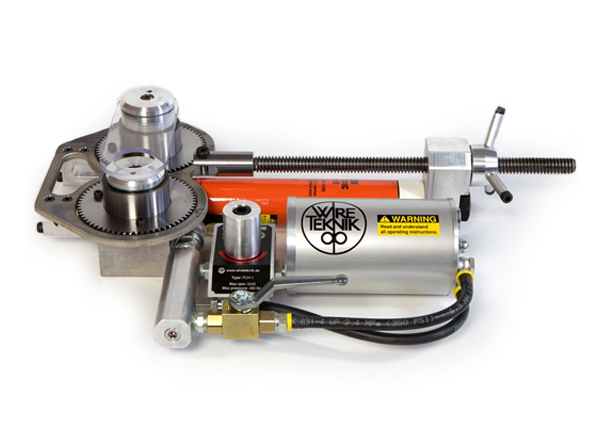
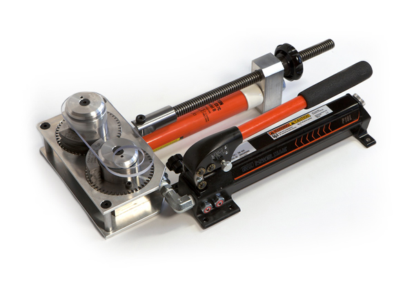
The most common use of swaging is to attach fittings to pipes or cables (also called wire ropes); the parts loosely fit together, and a mechanical or hydraulic tool compresses and deforms the fitting, creating a permanent joint. Pipe flaring machines are another example. Flared pieces of pipe are sometimes known as "swage nipples", "pipe swages", or "reducing nipples". In furniture, legs made from metal tubing (particularly in commercial furniture) are often swaged to improve strength where they come in contact with the ground, or casters.
In sawmills, a swage is used to flare large bandsaw or circle saw teeth, which increases the width of the cut, called the kerf. A clamp attaches a mandrel and die to the tooth and the eccentric die is rotated, swaging the tip. A much earlier version of the same operation used a hardened, shaped swage die and a hand held hammer. Saw teeth formed in this way are sometimes referred to as being "set". A finishing operation, shaping, cold works the points on the tooth sides to flats. It might be considered as a side swage. This slightly reduces the tooth width but increases the operating time between "fittings". Swaging is a major advance over filing as the operation is faster, more precise and greatly extends the working life of a saw.
When dealing with rubber components with mold bonded metal sleeves, swaging provides a more controlled and cost-effective alternative to "shooting" the rubber part into a metal sleeve, where an intensive and less dependable secondary operation is needed to finish the product. A metal can with a bonding component (such as phosphate) is painted to the inside diameter, and molten rubber is injected into the metal sleeve. This creates a product that when cooled may be swaged to the desired size. The second reason for this is that the product is more reliable, and during the swaging process the rubber is more relaxed when the outside can to which the rubber is bonded has its diameter reduced, changing the springrate (K) values and damping coefficient (C) of the rubber. After swaging, any inconsistencies in the metal and rubber have been minimized.
In internal ballistics, swaging describes the process of the bullet entering the barrel and being squeezed to conform to the rifling. Most firearm bullets are made slightly larger than the inside diameter of the rifling, so that they are swaged to engage the rifling and form a tight seal upon firing. Compare to obturate.
In ammunition manufacture, swaged bullets are bullets manufactured by compressing metal at room temperature into a die to form it into the shape of a bullet. The other common manufacturing method is casting, which uses molten metals poured into a mold. Since metals expand when heated and contract when cooled, cast bullets must be cast with a mold slightly larger than the desired finish size, so that as the molten metal cools, it will harden at just the right point to shrink to the desired size. In contrast, swaged bullets, since they are formed at the temperature at which they will be used, can be formed in molds of the exact desired size. This means that swaged bullets are generally more precise than cast bullets. The swaging process also leads to fewer imperfections, since voids commonly found in casting would be pressed out in the swaging process. The swaging process in reference to cold flow of metals into bullets is the process not of squeezing the metals into smaller forms but rather pressing smaller thinner items to form into shorter and slightly wider shapes.
Individuals who make their own bullets usually are not aware of available manual specialized equipment and dies required for swaging bullets,cast bullets. To get high precision results, it is common to cast the bullets slightly oversized, then swage the resulting castings through a die to do the final forming. Since the amount of pressure required to size the bullet is far less than that required to form a bullet, a simple mechanical press can be used, often the same press used for handloading ammunition.
In surgery, the thread used in sutures is often swaged to an eyeless needle in order to prevent damage as the needle and suture thread are drawn through the wound.
In musical instrument repair the usual term on both sides of the Atlantic is swedging, not swaging, though it is generally acknowledged that the former derives from the latter. Keyed instruments such as the clarinet, bassoon, oboe and flute need swedging when years of key movement has worn or compressed the metal of the hinge tube they swivel on and made it slightly shorter, so that the key can travel along the rod it is mounted on instead of being held firmly between the posts attaching the rod to the body of the instrument. This gives rise to floppy keys and a poor air-seal and needs to be corrected by lengthening (swedging) the hinge tube. This is a job that needs to be done by hand, and swedging pliers with highly polished oval holes in the jaws to fit common sizes of hinge tubes are often used to achieve this, though various proprietary designs of swedging tools are available to do the same job more efficiently.
Bass strings in pianos are generally constructed with round—sometimes hexagonal—drawn-steel cores, over which copper is wound. Especially on round core wire, the last several inches of the area where the winding terminates is often flattened—swaged—to create a grabbing point for the copper winding material.
As swaging is a technique in which cold metal is formed over a grooved tool or swage, the term was adopted in the field of automotive styling to describe when two panels were brought together, an edge of one panel was swaged so to overlap the other to create the impression of one continuous surface.
A lockbolt is a fastener similar to a bolt in appearance and function. However, instead of using screw threads which connect to a nut using a turning motion, a lockbolt has annular grooves around the shaft of the bolt (pin). After placing the lockbolt in a hole, a threadless collar is forced at high pressures around the annular grooves, deforming the collar and permanently locking it into place around the grooves. Swaging is the generic term for setting a lockbolt and collar assembly. During the installation cycle of a lockbolt, the collar is deformed around the pin with locking grooves using special tooling. The tool engages onto the pintail, which is an extra portion of pin material protruding past the collar that the tool grabs and pulls. This force on the pintail pushes the joint together, and the conically-shaped cavity of the tooling is forced down the collar, which reduces its diameter and progressively swages the collar material into the grooves of the harder pin. As the force required for swaging increases during the process, the installation is finalised when the pintail breaks off.blind rivets ("pop rivets" in some regions), though the way the collar material"s plastic deformation is achieved is different. Some tools are capable of "setting" both variants, as in both cases traction is applied to a sacrificial pintail.
Headword "swage." Webster"s Third New International Dictionary, Unabridged. Merriam-Webster, 2002. (Online version requires subscription to view.) http://unabridged.merriam-webster.com (Accessed 2007 March 10.)

1 NATIONAL SWAGING MACHINE AND DIE WARNING, USE, MAINTENANCE AND APPLICATION INFORMATION National Four Post WARNING Misuse of swaging machine can result in serious injury or death. READ, UNDERSTAND, AND FOLLOW all the information in this warning document and the instructions shown in Wire Rope End Terminations User s Manual before operating the swaging machine. machine operators must be trained in accordance with the information supplied by The Crosby Group LLC. THE SWAGING MACHINE OWNER IS RESPONSIBLE FOR THE TRAINING AND THE SAFE OPERATION OF THE SWAGING MACHINE. Do not swage oversize parts. Only swage parts of the proper design, material and hardness. If misused, dies and/or die holders may break. PROTECT YOURSELF AND OTHERS:Always stay away from the sides of the swaging machine during swaging operations and alert others in your work area. Do not shim between dies. Do not shim die or die holder unless swaging aluminum sleeves. Do not use die holders that are damaged or have loose side rails or side plates. Tie rod nuts must be secured to the tie rods with a secondary retention system. Keep head, hands, and body away from moving swaging machine and die parts. Consult die manufacturer for correct use of their product. Adjust swaging machine tonnage to the Working Load Limit (WLL) tonnage shown on the die block being used. If the Working Load Limit is not legible, refer to Die height & width and corresponding Working Load Limit (See Table 1). Failure to do so can result in serious injury or death. Operation Safety NEVER use dies that are cracked, worn or abraded (galled). NEVER use dies that have an oversized cavity. ALWAYS use a matched set of dies. When swaging steel fittings,do NOT SHIM DIES. Dies for steel fittings must be free to float and align one to the other. When swaging aluminum fittings, THE STEEL DIES MUST BE SHIMMED. Shim the side of the die to ensure the proper cavity alignment for flash removal. NEVER shim between the dies. When Crosby National fittings, use only the proper capacity swaging machine for the size of fitting used (See Capacity Chart). If the swaging machine capacity exceeds the die block Working Load Limit rating, adjust the swaging machine tonnage to the Working Load Limit shown on the die block being used. See Table 1 for die block Working Load Limit. Always use the correct size and type of die for the size wire rope fitting used. Make sure that the manufacturer s die retention locking pin, bolt, or other device is engaged and has secured the die before swaging. Make sure that the dies are straight, parallel, and perpendicular to each other before and during the swaging procedure. Always lubricate die faces and cavities with light weight oil. Progressive swaging of fittings must be done in accordance with procedure shown in Wire Rope End Terminations User s Manual. Only open channel dies are to be used. Stop swaging when the cavity side of both dies touch. Observe the die closure from above and slightly to the side. The best position is to stand 45 degrees to either side of the front. Make sure part is swaged to the recommended after swage dimensions (See Crosby General Catalog or Wire Rope End Terminations User s Manual, Die Guide, or Die Chart). If a swage fitting other than a Crosby National is used, determine adequacy of the termination by a destructive pull test. All swage sockets must be swaged with socket head adjacent to the socket relief (largest radius) on the die. For special applications or conditions, contact Crosby National (501) Die Size (Height x Width) TABLE 1 Working Load Limit (WLL)* 2 x 3-1/2 200 Ton Mark Series 2-1/2 x Ton National 2-1/2 x Ton Mark Series 4 x 7 1,200 Ton Mark Series 5 x 7 1,500 Ton National 6 x 12 3,000 Ton National * Note: These Working Load Limits are for Crosby National Die Blocks only. The Working Load Limits of die blocks from other manufacturers may vary. 65
2 Inspection Maintenance Safety Make sure the swager is in good operating condition and that all gauges, indicators and controls are working properly. Make sure all bolts and nuts are in place and tightened to recommended torque as shown in Table A, on page 13 for new style swaging machines, and Table B on page 14 for current swaging machines. Load block or die base plate surfaces must be to manufacturers specifications for thickness and flatness to provide complete support of the die during swaging. Make sure die holder side rails are not bent, loose or damaged. Clean dies and die holder surfaces. Keep free of metal shavings, slag, grit, sand, floor dry, etc. Lubricate the four guide bushings daily with light oil. 66 Die Working Load Limit Pressure Adjustment on Lower Cylinder National 500 Ton through 1500 Ton s Follow this procedure to adjust swaging tonnage (pressure) on your swaging machine. 1. Install the die holder(s) or die adapter with the dies to be used. 2. Bring the dies together (without a part in the dies) until they just touch. 3. Turn the tonnage control valve, which is located on the control panel left of the tonnage gauge, counter-clockwise about (6) six turns or until knob no longer turns. 4. Now (without a part in the dies) apply pressure to the dies by pressing the foot pedal marked up. A. If the tonnage is lower than desired Working Load Limit, turn the valve clockwise while continuing to press the foot pedal marked up until desired Working Load Limit is reached. B. If tonnage is higher than desired Working Load Limit, release pressure by pressing the pedal marked down. Then repeat steps 2 through 4. Hydraulic Size Capacity Chart for Swage Sleeves, Ferrules and Buttons Method 500 Ton Full Die 1000 Ton Full Die 1500 Ton Full Die Die Size (in.) Mark Series 2-1/2 x 5 4 x 5 4 x 7 6 x 12 Largest Fitting Allowed to be Swaged (in.)* S-505 Sleeve S-506 Sleeve S-510 Ferrules S-409 Buttons 1-1/2 1-1/4* 9/16* 7/8* 2-1/2 1-1/4* 9/16* 1-1/4* 3-1/2 1-1/4* 9/16* 1-1/4* 3000 Ton Full Die 6 x /2 1-1/4* 9/16* 1-1/4* * Largest size fitting available. Inspect the rods for corrosion. Use #000 emery cloth or steel wool to maintain a high polish surface. Do not increase the hydraulic system pressure above the factory preset pressure of: 6500 psi for 500 ton, 1000 ton and 1500 ton swaging machines 5000 psi for 3000 ton swaging machine. Under ordinary operating conditions, drain and clean reservoir every two (2) years. Make certain that the hydraulic reservoir is full when the swager is in the full open position. Filters inside of the reservoir should be cleaned every time the reservoir is drained and cleaned. The Racine tell-tale suction filter should be cleaned every six (6) months. Die Working Load Limit Pressure Adjustment on 3000 Ton For reducing tonnage, use selector switch on front of control panel to select lower tonnage (approximately 1500 Tons) or 3000 Ton. Hydraulic Size WARNING WARNING ALWAYS USE 5 X 7 OR 6 X 12 DIES AT 1500 TON SETTING. USE ONLY 6 X 12 DIES ON TONNAGE THAT EXCEEDS 1500 TONS. Capacity Chart for S-501 and S-502 Swage Socket Method Die Size (in.) Largest Fitting Allowed to be Swaged (in.)* Mark Series 2-1/2 x 5 Full Shank 3/4 4 x Tons Progressive 4 x 7 1-1/4 4 x 7 Full Shank 1000 Tons 1 Progressive 4 x 7 1-1/ Tons Full Shank 6 x /4 Progressive 6 x Tons Full Shank 6 x 12 2 Progressive 6 x /2 * Largest size fitting available.
5 Die Information CAUTION Improper die selection could result in significant loss of efficiency in the termination. National dies and die holders are made solely for swaging properly designed fittings on wire rope, and any other uses are prohibited. The swaging operation results in a high degree of cold metal flow. The movement that occurs between the fitting and the dies will cause wear of the dies. Therefore, to prolong the life of the dies, it is important to always lubricate die faces and cavities between each pass with a light weight oil or high pressure grease. When scores appear in the die cavities, the dies should be removed from service. NEVER EXCEED THE WORKING LOAD LIMIT OF DIES OR DIE HOLDERS. All National Standard dies 1/4 through 1 include an open channel die cavity and a tapered die cavity in the same die block. Dies for S-505 Standard Steel Sleeves (Flemish Eyes) Die sizes for 1/4 through 1 1/4 through 1 Standard Steel S-505 sleeves on Flemish Eye terminations requires the use of the taper cavity only. Refer to page 24 of the Wire Rope End Termination User s Manual for proper die selection. Die sizes for 1-1/8 and above 1-1/8 and larger Standard Steel S-505 sleeves on Flemish Eye terminations requires using 2 sets of open channel dies (1st stage and 2nd stage) for each size. Beginning with the 1st stage die and finishing with the 2nd stage die will achieve proper after swage dimensions. Dies for S-505 Sleeves 1-1/8 and larger are single cavity with open channel. Refer to page 24 of the Wire Rope End Termination User s Manual for proper die selection. Using S-505 Sleeves with Metric Ropes Although Crosby National S-505 Standard Steel sleeves are designed to be used with most metric ropes, there are selected intermediate sizes of metric ropes that when swaged in standard National dies utilizing Crosby National S-505 sleeves do not achieve required after swage dimensions and efficiencies. To ensure all 505 sleeves achieve the required efficiency when used with metric ropes, Crosby provides special National swaging dies to be used in conjunction with selected size metric ropes. These new dies will produce the required efficiencies and after swage dimensions. The table found on Page 25 of the Wire Rope End Termination User s Manual identifies the new dies that are required to properly swage the selected intermediate size wire ropes not covered in the standard product offering found on Page 24 of the manual. Dies for 6mm through 26mm (except 12mm, 20mm and 24mm) on 6mm through 26mm metric ropes for Flemish Eye slings requires the selection of the proper S-505 Standard Steel sleeve and the use of the tapered cavity only. Refer to page 24 of the Wire Rope End Termination User s Manual for proper sleeve and die selection. Dies for 12mm, 20mm and 24mm on 12mm, 20mm and 24mm metric ropes for Flemish Eye slings requires the selection of the proper S-505 Standard Steel sleeve and the use of both the open cavity and tapered cavity in special dies. Refer to page 25 of the Wire Rope End Termination User s Manual for proper sleeve and die selection. Dies for 28mm and larger on 28mm and larger metric ropes for Flemish Eye slings requires the selection of the proper S-505 Standard Steel sleeve and the use of 2 sets of open channel dies (1st stage and 2nd stage) for each size. Beginning with the 1st stage die and finishing with the 2nd stage die will achieve proper after swage dimensions. Dies for S-505 sleeves 28mm and larger are single cavity with open channel. Refer to page 24 of the Wire Rope End Termination User s Manual for proper sleeve and die selection. Important: If the specific size metric rope required is not listed on page 24 of the Wire Rope End Termination User s Manual refer to Intermediate Metric Die Chart on page 25 of the manual for proper sleeve and die selection. Dies for QUIC-PASS System 1/4 through 1-1/2 The QUIC-PASS swaging system allows Flemish style wire rope terminations to be swaged in only two passes. This is accomplished while maintaining currently published efficiency ratings and utilizing National Swage S-505 Standard COLD TUFF Steel Sleeves. The special design of the QUIC-PASS dies allows the swaging process to be completed in just two passes, resulting in a 50-75% reduction in the number of passes required with conventional swaging systems. Unlike standard round dies, the QUIC-PASS dies close completely with each pass, resulting in an increase in overall swaging process efficiencies (the job can be performed quicker), a reduction in the complexity of swaging (the concern for excess flashing between dies has been eliminated) and a reduction in training time needed for operators (more user friendly). The finished sleeve has a Hex appearance that provides a QUIC-CHECK look to determine if the termination has been swaged and provides a flat surface that allows for ease of I.D. stamping on the finished sleeve. Refer to page 24 of the Wire Rope End Termination User s Manual for proper die selection. 69
6 Dies for S-501 & S-502 Swage Sockets all S-501 & S-502 Swage Sockets requires the use of single cavity die. This is a special die designed with a relief for swage sockets and extra length to swage the full length of the shank. Refer to pages 36 and 37 of the Wire Rope End Termination User s Manual for proper die selection. Swage Sockets for Spiral Strand Rope Our tests indicate that if the spiral strand is 1 x 19 or greater, and the ultimate strength does not exceed Table 4 of ASTM A586, you can use dies for size swage sockets up to the 1-1/4. For sizes greater than 1-1/4 the following table will apply: If the strand is of greater strength than Table 4 or has less metallic area, we must recalculate the design and test for adequacy. Two Cavity Die Dies for S-506 Turnback Sleeves Turnback eye terminations using 5/16 through 1 S-506 Sleeves utilize the S-505 Standard Steel Sleeve die (1st Stage open channel die only). The 1-1/4 S-506 Sleeve utilizes the 1-3/8 socket (S-501 and S-502) die. Refer to page 46 of the Wire Rope End Termination User s Manual for proper die selection. Dies for S-409 Buttons Buttons are swaged in open channel dies. Refer to page 42 of the Wire Rope End Termination User s Manual for proper die selection. Specific recommended swaging practices can be found in each product section of this brochure. The proper die selection and the recommended maximum after swage dimensions are referenced in the section of this brochure that contains the product you are swaging. This information can also be found in The Crosby General Catalog (See Section Wire Rope End Terminations ), the National Swage Die Guide, or by referring to the National Swage Die Chart. Dies and die adapters to fit other type swaging machines are available upon request (Refer to page 19). Never use dies that are cracked, worn or abraded (galled). Single Cavity Die 70
7 After Swage Inspection Procedures WARNING Read, understand, and follow these instructions before using the National QUIC-PASS System. Improper after swage dimensions can result in sling failure resulting in property damage, serious injury or death. Always gauge or measure the after swage dimensions to ensure proper sling performance. Using National System with ropes and termination styles other than shown in these procedures may reduce the performance of the termination and lead to premature failure. When using rope constructions other than shown in this procedure, the termination must be destructive tested and documented to prove adequacy of the assembly to be manufactured. The QUIC-PASS System is designed only for Flemish Eye terminations using National S-505 Standard Steel Sleeves. The QUIC-PASS System is not designed for Cable-Laid wire rope slings or fiber core wire rope. Checking Dimensions One of the important considerations in producing a quality termination is the overall diameter of the fitting after the swaging process is complete. Since all dies wear, and the swaged fitting used in terminations have spring back, the results of swaging should be checked periodically to determine the wear condition of the die as well as to ensure the fitting is swaged to proper dimensions. Key Facts About After Swage Dimensions: 1. In addition to worn dies, not achieving the proper after swage dimension can also be due to the die not being fully closed during swaging. Dies showing excessive wear should be replaced. 2. The effective swaging that dies can accomplish stops when the die lands touch each other. Any continued swaging adds needless wear and strain on the dies and swaging machine. 3. By placing a light oil on the die faces and in the cavity, the dies will be lubricated as well as protected. 4. The oozing of the oil from the faces of the dies as they touch will indicate when the dies have closed. At this point, stop the swaging cycle. 5. Additional swaging adds needless wear and strain to the dies and swaging machine. 6. Never use dies that are cracked, worn or abraded (galled). 7. The Crosby Group does not recommend the checking of die dimensions as an acceptable method of determining the quality of a swage sleeve, button, ferrule, or socket. 8. It is our recommendation that the checking of the after swage dimension of the swaged fitting is the most accurate indicator of a properly swaged termination. Measuring the die cavity only is not an acceptable process control check. 9. If the die cavity wears, the dies are not closed completely during swaging. If an inadequate number of presses are used, it could be quickly identified by checking the after swage dimension of the part. 10. not producing sufficient tonnage will affect after swage dimensions. No-Go Gauge Information To assist in checking the after swage dimensions of the fitting, the Crosby Group provides the National No-Go Gauges. When used correctly the National No-Go Gauges can determine if the fittings were swaged to the proper diameter. We would recommend that all Crosby products or product swaged in Crosby dies be checked with the proper gauge to determine the acceptability of the swaging process. Gauges are made of hardened alloy steel and machined to strict tolerances. Gauge can be used to verify that all fittings have been swaged properly. After swage dimensions not within the maximum limits may result from worn dies or improper swaging techniques. Other type gauges are available upon request. National No-Go Gauges are available for a variety of products (See Table 1). No-Go Gauges and QUIC-PASS No-Go Gauges are not interchangeable. Table 1 Fitting and Size Part No. 505 Sleeve 1/4-7/ Sleeve 1-1-1/ Sleeve 1-3/ Sleeve Sleeve 2-1/ Sleeve 2-1/ Sleeve 2-3/ Sleeve Sleeve 3-1/ Sleeve 3-3/ Sleeve /502 Socket 1/ /502 Socket 1-1/8-1-3/ /502 Socket Using No-Go Gauges When swaged properly, the gauge will go up and down (see Figure 1) and around the full length of the fitting (see Figure 2). For the proper after swage dimensions, see the section in this publication for the specific product you are swaging. Figure 1 Figure 2 71
8 QUIC-PASS No-Go Gauges As a further aid, QUIC-PASS No-Go gauges are available for checking the sleeve s dimensions after swaging is complete. Gauges are made of hardened alloy steel and machined to strict tolerances. Gauge can be used to verify that all sleeves have been swaged properly. After Swage dimensions not within the maximum limits may result from worn dies or improper swaging techniques. QUIC-PASS No-Go Gauges Sleeve and Size Stock No. No-Go Gauge for S-505 1/4-7/ No-Go Gauge for S / No-Go Gauge for S /8-1-1/ QUIC-PASS Maximum After Swage Dimensions Size (in.) Maximum After Swage Dimension (in.) 1/ /16-3/ /16-1/ /16-5/ / / / / / / Stock No Stock No Stock No Use a National QUIC-PASS No-Go Gauge to check the after swage dimensions to ensure that it has been swaged to the proper dimension. When swaged properly, the gauge will slide up and down the full length of the sleeve on all three sets of opposing flats Crosby does not recommend a Texas Tuck style termination with Crosby National S-505 COLD TUFF Standard Steel Sleeves. Only Crosby National S-505 COLD TUFF Standard Steel Sleeves are recommended when using the QUIC- PASS System. National S-505 Standard Steel Sleeves, when used with the QUIC-PASS System, are only recommended for use with one (1) part 6 X 19 or 6 X 37, IPS or XIP (EIP), XXIP (EEIP), RRL, IWRC rope. The condition of the swaging machine can cause sleeve After Swage size not to be within the proper dimensions. Example: worn bushings, loose tie rods, loose die holders, misaligned platens, worn pins, worn linkage, etc. Important Safety Information dies being worn, damaged, misused, or undersized can cause sleeve After Swage size not to be within the proper dimension. die holders excessively worn, damaged, misused or loose can cause sleeve After Swage size not to be within the proper dimension. Only use QUIC-PASS dies and die holders inspected and properly secured in National swaging machines. Always refer to Warning and Application information found in the Crosby General Catalog and Wire Rope End Terminations User s Manual. 72


 8613371530291