
rotation resistant wire rope inspection in stock
(1) A competent person must begin a visual inspection prior to each shift the equipment is used, which must be completed before or during that shift. The inspection must consist of observation of wire ropes (running and standing) that are likely to be in use during the shift for apparent deficiencies, including those listed in paragraph (a)(2) of this section. Untwisting (opening) of wire rope or booming down is not required as part of this inspection.
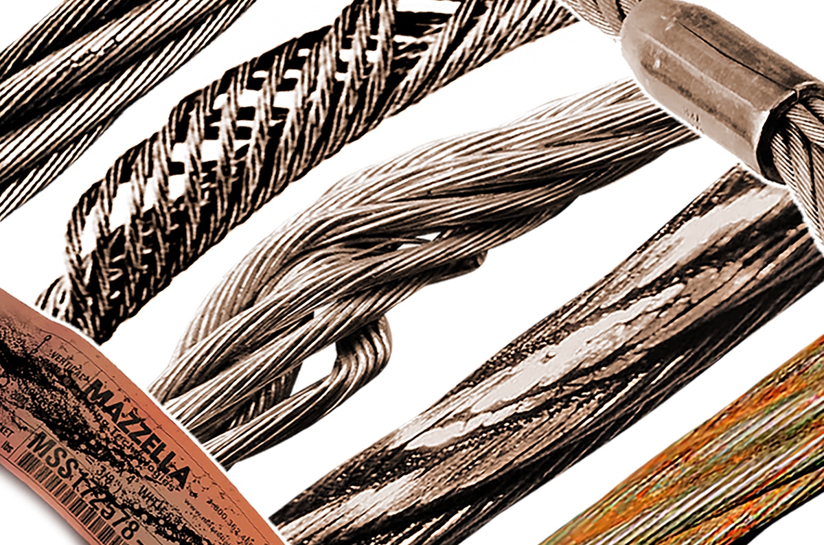
(A) Significant distortion of the wire rope structure such as kinking, crushing, unstranding, birdcaging, signs of core failure or steel core protrusion between the outer strands.
(1) In running wire ropes: Six randomly distributed broken wires in one rope lay or three broken wires in one strand in one rope lay, where a rope lay is the length along the rope in which one strand makes a complete revolution around the rope.
(2) In rotation resistant ropes: Two randomly distributed broken wires in six rope diameters or four randomly distributed broken wires in 30 rope diameters.
(3) In pendants or standing wire ropes: More than two broken wires in one rope lay located in rope beyond end connections and/or more than one broken wire in a rope lay located at an end connection.
(i) If a deficiency in Category I (see paragraph (a)(2)(i) of this section) is identified, an immediate determination must be made by the competent person as to whether the deficiency constitutes a safety hazard. If the deficiency is determined to constitute a safety hazard, operations involving use of the wire rope in question must be prohibited until:
(B) If the deficiency is localized, the problem is corrected by severing the wire rope in two; the undamaged portion may continue to be used. Joining lengths of wire rope by splicing is prohibited. If a rope is shortened under this paragraph, the employer must ensure that the drum will still have two wraps of wire when the load and/or boom is in its lowest position.
(ii) If a deficiency in Category II (see paragraph (a)(2)(ii) of this section) is identified, operations involving use of the wire rope in question must be prohibited until:
(A) The employer complies with the wire rope manufacturer"s established criterion for removal from service or a different criterion that the wire rope manufacturer has approved in writing for that specific wire rope (see § 1926.1417),
(C) If the deficiency is localized, the problem is corrected by severing the wire rope in two; the undamaged portion may continue to be used. Joining lengths of wire rope by splicing is prohibited. If a rope is shortened under this paragraph, the employer must ensure that the drum will still have two wraps of wire when the load and/or boom is in its lowest position.
(B) If the deficiency (other than power line contact) is localized, the problem is corrected by severing the wire rope in two; the undamaged portion may continue to be used. Joining lengths of wire rope by splicing is prohibited. Repair of wire rope that contacted an energized power line is also prohibited. If a rope is shortened under this paragraph, the employer must ensure that the drum will still have two wraps of wire when the load and/or boom is in its lowest position.
(iv) Where a wire rope is required to be removed from service under this section, either the equipment (as a whole) or the hoist with that wire rope must be tagged-out, in accordance with § 1926.1417(f)(1), until the wire rope is repaired or replaced.
(2) The inspection must include any deficiencies that the qualified person who conducts the annual inspection determines under paragraph (c)(3)(ii) of this section must be monitored.
(3) Wire ropes on equipment must not be used until an inspection under this paragraph demonstrates that no corrective action under paragraph (a)(4) of this section is required.
(1) At least every 12 months, wire ropes in use on equipment must be inspected by a qualified person in accordance with paragraph (a) of this section (shift inspection).
(ii) The inspection must be complete and thorough, covering the surface of the entire length of the wire ropes, with particular attention given to all of the following:
(iii) Exception: In the event an inspection under paragraph (c)(2) of this section is not feasible due to existing set-up and configuration of the equipment (such as where an assist crane is needed) or due to site conditions (such as a dense urban setting), such inspections must be conducted as soon as it becomes feasible, but no longer than an additional 6 months for running ropes and, for standing ropes, at the time of disassembly.
(B) If the deficiency is localized, the problem is corrected by severing the wire rope in two; the undamaged portion may continue to be used. Joining lengths of wire rope by splicing is prohibited. If a rope is shortened under this paragraph, the employer must ensure that the drum will still have two wraps of wire when the load and/or boom is in its lowest position.
(ii) If the qualified person determines that, though not presently a safety hazard, the deficiency needs to be monitored, the employer must ensure that the deficiency is checked in the monthly inspections.
(e) All documents produced under this section must be available, during the applicable document retention period, to all persons who conduct inspections under this section.
The following is a fairly comprehensive listing of critical inspection factors. It is not, however, presented as a substitute for an experienced inspector. It is rather a user’s guide to the accepted standards by which wire ropes must be judged. Use the outline to skip to specific sections:
Rope abrades when it moves through an abrasive medium or over drums and sheaves. Most standards require that rope is to be removed if the outer wire wear exceeds 1/3 of the original outer wire diameter. This is not easy to determine, and discovery relies upon the experience gained by the inspector in measuring wire diameters of discarded ropes.
All ropes will stretch when loads are initially applied. As a rope degrades from wear, fatigue, etc. (excluding accidental damage), continued application of a load of constant magnitude will produce incorrect varying amounts of rope stretch.
Initial stretch, during the early (beginning) period of rope service, caused by the rope adjustments to operating conditions (constructional stretch).
Following break-in, there is a long period—the greatest part of the rope’s service life—during which a slight increase in stretch takes place over an extended time. This results from normal wear, fatigue, etc.
Thereafter, the stretch occurs at a quicker rate. This means that the rope has reached the point of rapid degradation: a result of prolonged subjection to abrasive wear, fatigue, etc. This second upturn of the curve is a warning indicating that the rope should soon be removed.
In the past, whether or not a rope was allowed to remain in service depended to a great extent on the rope’s diameter at the time of inspection. Currently, this practice has undergone significant modification.
Previously, a decrease in the rope’s diameter was compared with published standards of minimum diameters. The amount of change in diameter is, of course, useful in assessing a rope’s condition. But, comparing this figure with a fixed set of values can be misleading.
As a matter of fact, all ropes will show a significant reduction in diameter when a load is applied. Therefore, a rope manufactured close to its nominal size may, when it is subjected to loading, be reduced to a smaller diameter than that stipulated in the minimum diameter table. Yet under these circumstances, the rope would be declared unsafe although it may, in actuality, be safe.
As an example of the possible error at the other extreme, we can take the case of a rope manufactured near the upper limits of allowable size. If the diameter has reached a reduction to nominal or slightly below that, the tables would show this rope to be safe. But it should, perhaps, be removed.
Today, evaluations of the rope diameter are first predicated on a comparison of the original diameter—when new and subjected to a known load—with the current reading under like circumstances. Periodically, throughout the life of the rope, the actual diameter should be recorded when the rope is under equivalent loading and in the same operating section. This procedure, if followed carefully, reveals a common rope characteristic: after an initial reduction, the diameter soon stabilizes. Later, there will be a continuous, albeit small, decrease in diameter throughout its life.
Deciding whether or not a rope is safe is not always a simple matter. A number of different but interrelated conditions must be evaluated. It would be dangerously unwise for an inspector to declare a rope safe for continued service simply because its diameter had not reached the minimum arbitrarily established in a table if, at the same time, other observations lead to an opposite conclusion.
Corrosion, while difficult to evaluate, is a more serious cause of degradation than abrasion. Usually, it signifies a lack of lubrication. Corrosion will often occur internally before there is any visible external evidence on the rope surface.
Pitting of wires is a cause for immediate rope removal. Not only does it attack the metal wires, but it also prevents the rope’s component parts from moving smoothly as it is flexed. Usually, a slight discoloration because of rusting merely indicates a need for lubrication.
Severe rusting, on the other hand, leads to premature fatigue failures in the wires necessitating the rope’s immediate removal from service. When a rope shows more than one wire failure adjacent to a terminal fitting, it should be removed immediately. To retard corrosive deterioration, the rope should be kept well lubricated with a clear wire rope lube that can penetrate between strands. In situations where extreme corrosive action can occur, it may be necessary to use galvanized wire rope.
Kinks are tightened loops with permanent strand distortion that result from improper handling when a rope is being installed or while in service. A kink happens when a loop is permitted to form and then is pulled down tight, causing permanent distortion of the strands. The damage is irreparable and the sling must be taken out of service.
Doglegs are permanent bends caused by improper use or handling. If the dogleg is severe, the sling must be removed from service. If the dogleg is minor, exhibiting no strand distortion and cannot be observed when the sling is under tension, the area of the minor dogleg should be marked for observation and the sling can remain in service.
Bird caging results from torsional imbalance that comes about because of mistreatment, such as sudden stops, the rope being pulled through tight sheaves, or wound on too small a drum. This is cause for rope replacement unless the affected section can be removed.
Particular attention must be paid to wear at the equalizing sheaves. During normal operations, this wear is not visible. Excessive vibration or whip can cause abrasion and/or fatigue. Drum cross-over and flange point areas must be carefully evaluated. All end fittings, including splices, should be examined for worn or broken wires, loose or damaged strands, cracked fittings, worn or distorted thimbles and tucks of strands.
After a fire or the presence of elevated temperatures, there may be metal discoloration or an apparent loss of internal lubrication. Fiber core ropes are particularly vulnerable. Under these circumstances the rope should be replaced.
Continuous pounding is one of the causes of peening. This can happen when the rope strikes against an object, such as some structural part of the machine, or it beats against a roller or it hits itself. Often, this can be avoided by placing protectors between the rope and the object it is striking.
Another common cause of peening is continuous working-under high loads—over a sheave or drum. Where peening action cannot be controlled, it is necessary to have more frequent inspections and to be ready for earlier rope replacement.
Below are plain views and cross-sections show effects of abrasion and peening on wire rope. Note that a crack has formed as a result of heavy peening.
Scrubbing refers to the displacement of wires and strands as a result of rubbing against itself or another object. This, in turn, causes wear and displacement of wires and strands along one side of the rope. Corrective measures should be taken as soon as this condition is observed.
Wires that break with square ends and show little surface wear have usually failed as a result of fatigue. Such fractures can occur on the crown of the strands or in the valleys between the strands where adjacent strand contact exists. In almost all cases, these failures are related to bending stresses or vibration.
If diameter of the sheaves, rollers or drum cannot be increased, a more flexible rope should be used. But, if the rope in use is already of maximum flexibility, the only remaining course that will help prolong its service life is to move the rope through the system by cutting off the dead end. By moving the rope through the system, the fatigued sections are moved to less fatiguing areas of the reeving.
The number of broken wires on the outside of a wire rope are an index of its general condition, and whether or not it must be considered for replacement. Frequent inspection will help determine the elapsed time between breaks. Ropes should be replaced as soon as the wire breakage reaches the numbers given in the chart below. Such action must be taken without regard to the type of fracture.
* All ropes in the above applications—one outer wire broken at the point of contact with the core that has worked its way out of the rope structure and protrudes or loops out of the rope structure. Additional inspection of this section is required.
Rope that has either been in contact with a live power line or been used as “ground” in an electric welding circuit, will have wires that are fused, discolored and/or annealed and must be removed.
On occasion, a single wire will break shortly after installation. However, if no other wires break at that time, there is no need for concern. On the other hand, should more wires break, the cause should be carefully investigated.
On any application, valley breaks—where the wire fractures between strands—should be given serious attention. When two or more such fractures are found, the rope should be replaced immediately. (Note, however, that no valley breaks are permitted in elevator ropes.)
It is good to remember that once broken wires appear—in a rope operating under normal conditions—a good many more will show up within a relatively short period. Attempting to squeeze the last measure of service from a rope beyond the allowable number of broken wires (refer to table on the next page) will create an intolerably hazardous situation.
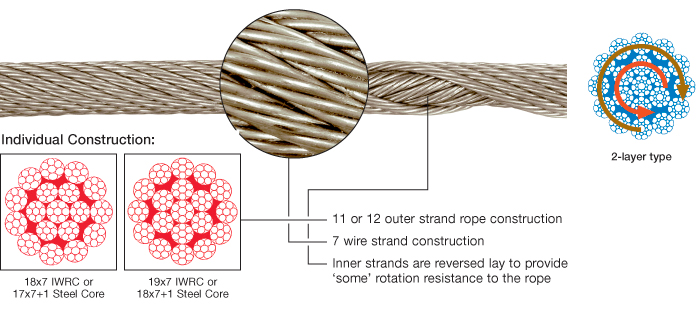
Recommended retirement criteria for all Rotation Resistant Ropes are 2 broken wires in 6 rope diameters or 4 broken wires in 30 rope diameters (i.e. 6 rope diameters for a 1″ diameter rope = 6″).
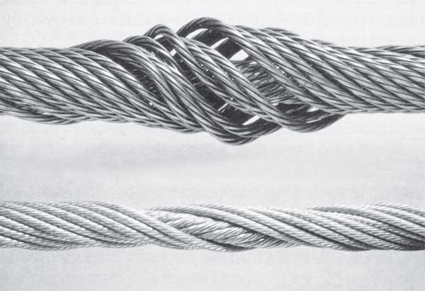
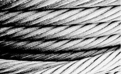
Distortion of Rotation Resistant Ropes, as shown below, can be caused by shock load / sudden load release and/or induced torque, and is the reason for immediate removal from service.

Rotation resistant ropes are known to provide the best and most economical services for specific applications. When the correct ropes are selected and appropriately used, they are unmatched in the lifting market. Elephant hoists greatly benefit from rotation resistant wires.
Rotation resistance is created when wires are laid in a contra-helical position. These ropes are different from standard construction types because rotation resistant ropes are required to meet a different and higher set of service requirements. The modes of wear and failure for these ropes vary more than standard constructions. Special operational needs make specific limitations and special handling necessary. These are not encouraged with standard constructions.
Testing on ropes that are resistant to rotation commonly shows that the total length of service for these ropes is shorter than that of standard construction ropes. The tests show that there is a need for separate guidelines for the use, inspection, retirement, and application of resistant ropes.
Using a swivel at the load hook for rotation resistant ropes results in unpredictable service life. This type of practice can potentially lead to unbalanced loading between outer and inner layers of strands. This typically results in core failure. Any significant changes in diameter found in a small length of operating rope should be retired and replaced. Make sure to use appropriate rigging supplies for all crane wire rope applications.
For more information on the benefits of rotation resistant ropes, you should not hesitate to give our team a call. Do not forget to ask about our V rope options.
Main difference between both types are the number of outer strands: 19x7 has 12 while 18x7 has just 11. In pactice this difference is neglectable; European ropes tend to be of the 18x7 type having 11 outer strands.
Using the rope to it’s maximum fatigue life will cause the rope to deteriorate from the inside out. Sudden rope failures may be the result. There have been fatal and catastrophic accidents involving this rope construction because of undetected inner rope fatigue.
It is much critical to inspect these rope on a regular basis. Immediately remove such ropes if you detect a difference in diameter between the working section and the the part in front of the wedge socket or safety drum wraps.
In this full length handbook, learn the basics of wire rope including how to choose and measure wire rope. Additionally, you will understand the fundamental mechanics behind our most popular rope constructions and classifications. Finally, you will learn the proper way to care for and use your wire rope, including end treatments, inspection, and removal criteria.
Twisted hoist lines can bring a construction project to a sudden halt, resulting in downtime. But the good news is that you can minimize block rotation through proper installation, handling and corrective measures. In this reference document, you will better understand torque and gain tips on how to reduce block rotation.
Our galvanized strand products meet or exceed ASTM specifications A475 and ASTM A363. In this reference document (an excerpt from the Wire Rope Users Handbook), you will learn what the strands are tested for. Additionally, a chart detailing the physical properties of zinc-coated steel wire strand is included.
Our industry has its fair share of terminology and phrases. In this reference document (an excerpt from the Wire Rope Users Handbook), you will be provided a comprehensive glossary of all Wire Rope words. From “Abrasion” to “Warrington”, your questions are answered here.
How long will your rope last? While there is not a simple answer, there are several factors involved. In this reference document (an excerpt from the Wire Rope Users Handbook), you will the factors affecting the longevity of your ropes life. Additionally, information regarding the cleaning and lubrication of your ropes is included.
There is a correct methodology behind measuring of wire rope diameter. Learn this methodology in this reference document (an excerpt from the Wire Rope Users Handbook). Also, the definition of design factor is available. And finally, detailed information regarding metric conversion and equivalents is included.
Yes, there is a RIGHT way to unreel, uncoil and store a wire rope. Learn the proper steps in this reference document (an excerpt from the Wire Rope Users Handbook). Additionally, the three stages of kinking are vividly displayed.
Wires are the basic building blocks of a wire rope. And, a rope core will greatly impact the performance of your rope. Learn how the number of wire strands and construction determine a wire rope classification. In this reference document (an excerpt from the Wire Rope Users Handbook), you will become familiar with the standard rope classifications and special rope constructions.
The types of wire, lay and performing greatly affect wire rope performance and operation. In this reference document (an excerpt from the Wire Rope Users Handbook), you will learn the basic types of wire used in ropes, the common grades of wire rope and the meaning of “lay”.
In this Product Bulletin, you will learn about the new rope description format that WireCo WorldGroup will follow in all of our product descriptions. This format will adopt symbols and designations that are part of ISO, ASTM, and other industry standards and specifications.
Rotation-resistant ropes can frequently provide the best and most economical service in specific applications, when you choose, handle and use them properly. In this reference document (an excerpt from the Wire Rope Users Handbook), you will learn the difference between Category 1, Category 2 and Category 3 Rotation-Resistant Rope.
Previously known as “aircraft” cable, and now known as “utility cable, these small diameter specialty ropes are used in a variety of applications, including control cables, window and door closures, different kind of remote control systems and boat riggings. In this reference document (an excerpt from the Wire Rope Users Handbook), you will learn how Union specialty small ropes are engineered and fabricated, and the special lubrication and testing they require. Additionally, a minimum breaking force and weights for 7x7, and 7x19 utility cable is included.
Our industry has its fair share of abbreviations. In this reference document (an excerpt from the Wire Rope Users Handbook), you will be provided a comprehensive glossary of all Wire Rope words. From “PRF” (preformed) to “XIP®” (Extra improved plow steel), your questions are answered here.
Swaged ropes and “Double-Swaged” ropes provide excellent strength for some specific applications. In this reference document (an excerpt from the Wire Rope Users Handbook), you will find the definition of swaged and PowerFlex (aka double-swaged) ropes. Minimum breaking force and weights charts for 6x19, 6x36, PowerFlex, 3x19 and 3x36 ropes are included.
Our most popular Tech Report, this Wire Rope Inspection Tech Report explains why periodic inspection of wire ropes are necessary. Learn how to properly inspect wire rope, what tools are necessary for inspection, and how to use inspection forms. Additionally, you will learn how often you should inspect your wire rope, what your ‘critical’ points are, how to inspect your end attachments, how to make an internal rope examination, how to inspect sheaves, and how to evaluate drums. Finally, you will understand how to properly measure rope diameter and rope lay.
In applications where a specific length is critical, the constructional stretch can be minimized by prestretching the rope prior to installation, HOWEVER, learn why WireCo WorldGroup advises against prestretching Tuf-Kote/PFV rope. After reading this product bulletin, you will understand the rationale behind WireCo WorldGroup’s recommendation against prestretching Tuf-Kote/PFV Rope.
Engineering and producing wire rope slings for your application is a highly specialized field - with exacting standards that we gladly live by. In this marketing flier, learn the different Union Wire Rope Sling constructions. Additionally learn more about Union Spelter Sockets (both open and closed). There are capacity and diameter charts associated with each product.
In this Product Bulletin, learn the various definition of "US made wire rope" including references to the Buy American Act and the Buy America Requirement. Additionally, learn how Union wire rope meets these definitions.
Most ropes are shipped with the ends seized as they are prepared for cutting, however, in some cases, the rope requires special end preparations. In this reference document (an excerpt from the Wire Rope Users Handbook), you will learn the two chosen methods for seizing cut ends of your wire ropes. Illustrations and step-by-step instructions are included.
All wire ropes will wear out eventually and gradually lose work capability throughout their service life. In this reference document (an excerpt from the Wire Rope Users Handbook), you will learn why periodic inspections are critical. The purposes for inspection, guidelines around timing and choosing the right person to inspect are included. Additionally, illustrations regarding “what to look for” in a wire rope is available.
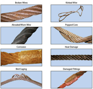
There is obvious evidence of wire rope wear and abuse, and specific criteria regarding removal of your wire rope. In this reference document (an excerpt from the Wire Rope Users Handbook), you will learn the various types of wear and abuse (illustrations included) and the exact removal criteria. A chart on when to replace your wire rope – based on number of broken wires is included.
In this product bulletin, learn why WireCo WorldGroup refers to XLT4 as a low-torque rope and not a rotation-resistant rope. Also included are the definitions of ASTM A1023 and ASME B30.5.
Rope diameter is specified by the user and is generally given in the equipment manufacturer’s instruction manual accompanying the machine on which the rope is to be used.
Rope diameters are determined by measuring the circle that just touches the extreme outer limits of the strands— that is, the greatest dimension that can be measured with a pair of parallel-jawed calipers or machinist’s caliper square. A mistake could be made by measuring the smaller dimension.
The right way to unreel.To unreel wire rope from a heavy reel, place a shaft through the center and jack up the reel far enough to clear the floor and revolve easily. One person holds the end of the rope and walks a straight line away from the reel, taking the wire rope off the top of the reel. A second person regulates the speed of the turning reel by holding a wood block against the flange as a brake, taking care to keep slack from developing on the reel, as this can easily cause a kink in the rope. Lightweight reels can be properly unreeled using a vertical shaft; the same care should be taken to keep the rope taut.
The wrong way to unreel.If a reel of wire rope is laid on its flange with its axis vertical to the floor and the rope unreeled by throwing off the turns, spirals will occur and kinks are likely to form in the rope. Wire rope always should be handled in a way that neither twists nor unlays it. If handled in a careless manner, reverse bends and kinks can easily occur.
The right way to uncoil.There is only one correct way to uncoil wire rope. One person must hold the end of the rope while a second person rolls the coil along the floor, backing away. The rope is allowed to uncoil naturally with the lay, without spiraling or twisting. Always uncoil wire rope as shown.
The wrong way to uncoil.If a coil of wire rope is laid flat on the floor and uncoiled by pulling it straight off, spirals will occur and kinking is likely. Torsions are put into the rope by every loop that is pulled off, and the rope becomes twisted and unmanageable. Also, wire rope cannot be uncoiled like hemp rope. Pulling one end through the middle of the coil will only result in kinking.
Great stress has been placed on the care that should be taken to avoid kinks in wire rope. Kinks are places where the rope has been unintentionally bent to a permanent set. This happens where loops are pulled through by tension on the rope until the diameter of the loop is only a few inches. They also are caused by bending a rope around a sheave having too severe a radius. Wires in the strands at the kink are permanently damagedand will not give normal service, even after apparent “re-straightening.”
When wire rope is wound onto a sheave or drum, it should bend in the manner in which it was originally wound. This will avoid causing a reverse bend in the rope. Always wind wire rope from the top of the one reel onto the top of the other.Also acceptable, but less so, is re-reeling from the bottom of one reel to the bottom of another. Re-reeling also may be done with reels having their shafts vertical, but extreme care must be taken to ensure that the rope always remains taut. It should never be allowed to drop below the lower flange of the reel. A reel resting on the floor with its axis horizontal may also be rolled along the floor to unreel the rope.
Wire rope should be attached at the correct location on a flat or smooth-faced drum, so that the rope will spool evenly, with the turns lying snugly against each other in even layers. If wire rope is wound on a smooth-face drum in the wrong direction, the turns in the first layer of rope will tend to spread apart on the drum. This results in the second layer of rope wedging between the open coils, crushing and flattening the rope as successive layers are spooled.
A simple method of determining how a wire rope should be started on a drum. The observer stands behind the drum, with the rope coming towards him. Using the right hand for right-lay wire rope, and the left hand for left lay wire rope, the clenched fist denotes the drum, the extended index finger the oncoming rope.
Clips are usually spaced about six wire rope diameters apart to give adequate holding power. They should be tightened before the rope is placed under tension. After the load is placed on the rope, tighten the clips again to take care of any lessening in rope diameter caused by tension of the load. A wire rope thimble should be used in the eye of the loop to prevent kinking.
U-bolt Clips.There is only one correct method for attaching U-bolt clips to wire rope ends, as shown in TheRightWayimage below. The base of the clip bears on the live end of the rope; the “U” of the bolt bears on the dead end.
Compare this with the incorrect methods. Five of the six clips shown are incorrectly attached—only the center clip in the top view is correct. When the “U” of the clip bears on the live end of the rope, there is a possibility of the rope being cut or kinked, with subsequent failure.
Proper seizing and cutting operations are not difficult to perform, and they ensure that the wire rope will meet the user’s performance expectations. Proper seizings must be applied on both sides of the place where the cut is to be made. In a wire rope, carelessly or inadequately seized ends may become distorted and flattened, and the strands may loosen. Subsequently, when the rope is operated, there may be an uneven distribution of loads to the strands; a condition that will significantly shorten the life of the rope.
Either of the following seizing methods is acceptable. Method No. 1 is usually used on wire ropes over one inch in diameter. Method No. 2 applies to ropes one inch and under.
Method No. 1: Place one end of the seizing wire in the valley between two strands. Then turn its long end at right angles to the rope and closely and tightly wind the wire back over itself and the rope until the proper length of seizing has been applied. Twist the two ends of the wire together, and by alternately pulling and twisting, draw the seizing tight.
The Seizing Wire. The seizing wire should be soft or annealed wire or strand. Seizing wire diameter and the length of the seize will depend on the diameter of the wire rope. The length of the seizing should never be less than the diameter of the rope being seized.
Proper end seizing while cutting and installing, particularly on rotation-resistant ropes, is critical. Failure to adhere to simple precautionary measures may cause core slippage and loose strands, resulting in serious rope damage. Refer to the table below ("Suggested Seizing Wire Diameters") for established guidelines. If core protrusion occurs beyond the outer strands, or core retraction within the outer strands, cut the rope flush to allow for proper seizing of both the core and outer strands.
The majority of wire rope problems occurring during operation actually begin during installation, when the rope is at its greatest risk of being damaged. Proper installation procedures are vital in the protection and performance of wire rope products.
Until the rope is installed it should be stored on a rack, pallet or reel stand in a dry, well-ventilated storage shed or building. Tightly sealed and unheated structures should be avoided as condensation between rope strands may occur and cause corrosion problems. If site conditions demand outside storage, cover the rope with waterproof material and place the reel or coil on a support platform to keep it from coming directly in contact with the ground.
While lubrication is applied during the manufacturing process, the wire rope must still be protected by additional lubrication once it is installed. Lubricants will dry out over a period of time and corrosion from the elements will occur unless measures are taken to prevent this from happening. When the machine becomes idle for a period of time, apply a protective coating of lubricant to the wire rope. Moisture (dew, rain, and snow) trapped between strands and wires will create corrosion if the rope is unprotected. Also apply lubricant to each layer of wire rope on a drum because moisture trapped between layers will increase the likelihood of corrosion.
Always use the nominal diameter as specified by the equipment manufacturer. Using a smaller diameter rope will cause increased stresses on the rope and the probability of a critical failure is increased if the rated breaking strength does not match that of the specified diameter. Using a larger diameter rope leads to shorter service life as the rope is pinched in the sheave and drum grooves which were originally designed for a smaller diameter rope. Just as using a different diameter rope can create performance problems, so can the use of an excessively undersized or oversized rope.
Measure the wire rope using a parallel-jawed caliper as discussed in Measuring Rope Diameter at the top of this page. If the rope is the wrong size or outside the recommended tolerance, return the rope to the wire rope supplier. It is never recommended nor permitted by federal standards to operate cranes with the incorrect rope diameter. Doing so will affect the safety factor or reduce service life and damage the sheaves and drum. Note that in a grooved drum application, the pitch of the groove may be designed for the rope’s nominal diameter and not the actual diameter as permitted by federal standards.
Wire rope can be permanently damaged by improper unreeling or uncoiling practices. The majority of wire rope performance problems start here.Improper unreeling practices lead to premature rope replacement, hoisting problems and rope failure.
Place the payout reel as far away from the boom tip as is practical, moving away from the crane chassis. Never place the payout reel closer to the crane chassis than the boom point sheave. Doing so may introduce a reverse bend into the rope and cause spooling problems. Follow the guidelines highlighted under Unreeling and Uncoiling and Drum Winding. Take care to determine whether the wire rope will wind over or under the drum before proceeding. If the wire rope supplier secured the end of the rope to the reel by driving a nail through the strands, ask that in the future a U-bolt or other nondestructive tie-down method be used; nails used in this manner damage the rope.
Take extra precaution when installing lang lay, rotation-resistant, flattened strand or compacted ropes. Loss of twist must be avoided to prevent the strands from becoming loosened, causing looped wire problems.
The end of the rope must be securely and evenly attached to the drum anchorage point by the method recommended by the equipment manufacturer. Depending on the crane’s regulatory requirements, at least two to three wraps must remain on the drum as dead wraps when the rope is unwound during normal operations. Locate the dead end rope anchorage point on the drum in relation to the direction of the lay of the rope. Do not use an anchorage point that does not correspond with the rope lay. Mismatching rope lay and anchorage point will cause the wraps to spread apart from each other and allow the rope to cross over on the drum. Very gappy winding will occur resulting in crushing damage in multilayer applications.
Back tension must be continually applied to the payout reel and the crewman installing the rope must proceed at a slow and steady pace whether the drum is smooth or grooved.Regardless of the benefits of a grooved drum, tension must be applied to ensure proper spooling. An improperly installed rope on a grooved drum will wear just as quickly as an improperly installed rope on a smooth drum. If a wire rope is poorly wound and as a result jumps the grooves, it will be crushed and cut under operating load conditions where it crosses the grooves.
Every wrap on the first or foundation layer must be installed very tightly and be without gaps. Careless winding results in poor spooling and will eventually lead to short service life. The following layers of rope must lay in the grooves formed between adjacent turns of the preceding layer of rope. If any type of overwind or cross-winding occurs at this stage of installation and is not corrected immediately, poor spooling and crushing damage will occur.
On a multilayer spooling drum be sure that the last layer remains at least two rope diameters below the drum flange top. Do not use a longer length than is required because the excess wire rope will cause unnecessary crushing and may jump the flange. Loose wraps that occur at any time must be corrected immediately to prevent catastrophic rope failure.
The use of a mallet is acceptable to ensure tight wraps, however a steel-faced mallet should be covered with plastic or rubber to prevent damage to the rope wires and strands.
Rotation-resistant ropes of all constructions require extra care in handling to prevent rope damage during installation. The lay length of a rotation-resistant rope must not be disturbed during the various stages of installation. By introducing twist or torque into the rope, core slippage may occur—the outer strands become shorter in length, the core slips and protrudes from the rope. In this condition the outer strands become over- loaded because the core is no longer taking its designed share of the load. Conversely, when torque is removed from a rotation-resistant rope core slippage can also occur. The outer strands become longer and the inner layers or core become overloaded, reducing service life and causing rope failure.
The plain end of a wire rope must be properly secured. If the entire cross section of the rope is not firmly secured, core slippage may occur, causing the core to pull inside the rope’s end and allowing it to protrude elsewhere, either through the outer strands (popped core) or out the other end of the line. The outer layer of the outside strands may also become overloaded as there is no complete core-to-strand support.
Secure the ends of the rope with either seizing or welding methods as recommended under Seizing Wire Rope. It is imperative that the ends be held together tightly and uniformly throughout the entire installation procedure, including attaching the end through the wedge socket and the drum dead end wedge
When installing a new line, connect the old line to the new line by using a swivel-equipped cable snake or Chinese finger securely attached to the rope ends. The connection between the ropes during change-out must be very strong and prevent torque from the old rope being transferred into the new rope.Welding ropes together or using a cable snake without the benefit of a swivel increases the likelihood of introducing torque into the new rope. A swivel-equipped cable snake is not as easy as welding the ropes, but this procedure can be mastered with a little patience and practice.

Wire ropes are largely used in marine environment or for rigging purposes. They receive considerable loads and thus suffer a great deal of mechanical damage throughout their service life. Moreover, research has shown that the major cause of wire rope failure is excessive deterioration and corrosion, lack of maintenance and inspection, and wrong usage resulting in early discarding, reduced safety and replacement cost increase.
Sometimes damage can be easily detected, while in other cases fractured wires may occur on the inside. Hence, wire ropes should be inspected and maintained by the right person (competent person assigned by the company), to assure they’re in perfect condition. Regular inspectionsensure high rope performance, long service lifetime , safety of personnel and equipment, and reduced operating costs.
All ropes (synthetic, high modulus and wire ropes) should be inspected before and after an operation. This guideline ensures maximum safety for both a ship’s personnel and equipment. Even though it’s difficult to determine the exact service life span of ropes, there is a way to have a more precise estimation about their efficient lifecycle. Calculating the exact time ropes have been in use (e.g mooring time, mooring conditions, weather and tidal conditions) is the answer. All in all, rope inspections should occur at least once a year.
Inspecting wire ropes in particular, comes with great responsibility. Inspection results should be recorded, and any defects noticed have to be reported and addressed properly. Some defects can be repaired, while in some cases replacing a wire rope is inevitable.
Periodical inspections ofvessel deck equipment is also crucial for maintaining the good condition of wire ropes. The condition of the drum, chocks, bitts, rollers, sheaves, cable clamps and other end fittings, affect the rope’s performance, threads and cords. Make sure to mark these parts during your overall inspection.
In order to help marine officers and staff conduct successful wire rope inspections – and keep an up-to-date record of them – we have created an inspection solution that helps in maintaining and monitoring a ship’s ropes and deck equipment.Learn more about Katradis inspection Neptune Solution
When calculating mass using F = Minimum Breaking Force, according to the wire rope’s diameter, you can determine the Minimum Breaking Massand therefore the wire’s max strength. When calculating mass using F = Safe Load according to the wire rope’s diameter, you can determine the Safe Load Mass,which is the advised load for this rope diameter.
The strands of a wire rope absorb the majority of the tensile force applied on the rope. Their design and manufacturing standards affect the level of fatigue resistance and resistance to abrasion. An easy way to understand which rope design is suitable for each purpose, is the wire rope classification.
Wire ropes are classified according to the number of strands in each construction and the number of wires in each strand. For example, a classification of 6X19 means that a wire rope of this type always has six strands, but its wires could be 15-26 per strand. This is because 19 is not the exact number of wires, but the classification of a wire number range.
Visual inspections are a common and fast way to assess wire rope condition. Both the standard and rotation resistant wire rope inspectionprocesscomply with the same four steps of examination. A ship’s crew can perform them as follows:
Steel wire rope distortion is obvious in most cases and can easily be identified by the inspector or the ship‘s crew. It usually occurs if load is suddenly applied or abruptly released (shock loading), or even if swift torque is forcefully induced.
Although not all of these deformations make the rope absolutely dangerous to use, they all may cause ropes to wear unevenly in time. This means inspections should take place more often, and distorted ropes should be handled with caution.
The rag and visual inspection is a good method for regular inspection intervals. The inspector pulls a rag along the rope trying to find broken wire cords. If the rug gets snagged by the rope, the inspector has to stop and assess the wire rope’s condition. Extreme caution should be exercised during the visual inspection, and under no circumstances should this method be the only one used to inspect wire ropes.
Tip: When you encounter a protruding wire end, bend it back and forth manually, until it separates from the wire. This will protect neighboring wires from wearing out.
Diameter reduction is a critical factor in steel wire rope wear and if not properly taken care of, it can result in rope breakage. Excessive abrasion, loss of core mass, corrosion or inner wire failure are all factors that contribute to diameter reduction.
To get an accurate measurement of the rope’s diameter, measure the rope at three different points at least 5 feet apart. Take the average of these three measurements to determine the true diameter.
Any measurements showing a reduction of ⅓ or more, indicate that a replacement should follow without delay. A diameter reduction of less than 1/3 still requires attention, and the inspector or the ship’s crew should be on guard in the next scheduled wire rope inspection.
Failure from abrasion or corrosion is a result of deficient deck equipment inspection or insufficient wire rope lubrication respectively. Internal corrosive damage is more difficult to identify than any other types of degradation. In most cases, the damage has progressed more than the external signs suggest.
Wire rope storage plays a significant role in the rope’s operation life.Wire rope corrosion and pitting can be avoided if ropes are safely stored in a clean, cool, dry and well-ventilated place. Steel wire ropes should not by any means rest on the floor, and should be protected from water, dust or any chemical fumes. Long term storage requires periodic greasing, turning the reel upside down for preventing grease dripping and possibly re-winding to another reel with larger inner tube diameter.
Wire ropes should be maintained with periodical lubrication. In order to prevent internal corrosion, a pressure lubricator is suggested to be used. In this case, a small amount of grease is used to lubricate the rope internally, while the deck stays grease-clean. Pressure lubricators clean the rope before they grease it so that the new grease enters a clean rope. The type of grease used is very important for maximum protection and greasing efficiency.
Steel wire ropes exposed to dirt, grime and other contaminants, have to be cleaned with a wire brush and petroleum (unless a pressure lubricator is used). Optimal cleaning of wire ropes can extend their service life and guarantee safe operations.
The reeling process is of high importance for the longevity of wire ropes. To protect them from being damaged, it is important that the surface of the drum is clean, smooth and dry. Improper reeling may cause wire-rope strands to spread or get flattened, when in contact with one another, as successive layers are being spooled and upper layers apply pressure on the lower ones.
Katradis S.A. offers a wide range of top quality wire ropes for shipping (mooring and hoisting operations), fishing and construction purposes. Our wire ropes have greater resistance to fatigue, and they distribute tension force equally among the rope strands. They are less likely to kink, providing higher staff safety and assuring operation success.Choose your new wire ropes


 8613371530291