
safe working load wire rope chart brands
Rope strength is a misunderstood metric. One boater will talk about tensile strength, while the other will talk about working load. Both of these are important measurements, and it’s worth learning how to measure and understand them. Each of these measurements has different uses, and here we’re going to give a brief overview of what’s what. Here’s all you need to know about rope strength.
Each type of line, natural fiber, synthetic and wire rope, have different breaking strengths and safe working loads. Natural breaking strength of manila line is the standard against which other lines are compared. Synthetic lines have been assigned “comparison factors” against which they are compared to manila line. The basic breaking strength factor for manila line is found by multiplying the square of the circumference of the line by 900 lbs.
Just being able to calculate breaking strength doesn’t give one a safety margin. The breaking strength formula was developed on the average breaking strength of a new line under laboratory conditions. Without straining the line until it parts, you don’t know if that particular piece of line was above average or below average. For more information, we have discussed the safe working load of ropes made of different materials in this article here.
It’s very important to understand the fundamental differences between the tensile strength of a rope, and a rope’s working load. Both terms refer to rope strength but they’re not the same measurement.
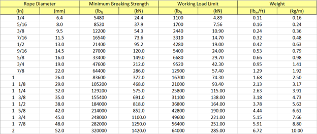
A rope’s tensile strength is the measure of a brand-new rope’s breaking point tested under strict laboratory-controlled conditions. These tests are done by incrementally increasing the load that a rope is expected to carry, until the rope breaks. Rather than adding weight to a line, the test is performed by wrapping the rope around two capstans that slowly turn the rope, adding increasing tension until the rope fails. This test will be repeated on numerous ropes, and an average will be taken. Note that all of these tests will use the ASTM test method D-6268.
The average number will be quoted as the rope’s tensile strength. However, a manufacturer may also test a rope’s minimum tensile strength. This number is often used instead. A rope’s minimum tensile strength is calculated in the same way, but it takes the average strength rating and reduces it by 20%.
A rope’s working load is a different measurement altogether. It’s determined by taking the tensile strength rating and dividing it accordingly, making a figure that’s more in-line with an appropriate maximum load, taking factors such as construction, weave, and rope longevity into the mix as well. A large number of variables will determine the maximum working load of a rope, including the age and condition of the rope too. It’s a complicated equation (as demonstrated above) and if math isn’t your strong point, it’s best left to professionals.
However, if you want to make an educated guess at the recommended working load of a rope, it usually falls between 15% and 25% of the line’s tensile strength rating. It’s a lotlower than you’d think. There are some exceptions, and different construction methods yield different results. For example, a Nylon rope braided with certain fibers may have a stronger working load than a rope twisted out of natural fibers.
For safety purposes, always refer to the information issued by your rope’s manufacturer, and pay close attention to the working load and don’t exceed it. Safety first! Always.
If you’re a regular sailor, climber, or arborist, or just have a keen interest in knot-tying, be warned! Every knot that you tie will reduce your rope’s overall tensile strength. Some knots aren’t particularly damaging, while others can be devastating. A good rule of thumb is to accept the fact that a tied knot will reduce your rope’s tensile strength by around 50%. That’s an extreme figure, sure, but when it comes to hauling critical loads, why take chances?
Knots are unavoidable: they’re useful, practical, and strong. Splices are the same. They both degrade a rope’s strength. They do this because a slight distortion of a rope will cause certain parts of the rope (namely the outer strands) to carry more weight than others (the inner strand). In some cases, the outer strands end up carrying all the weight while the inner strands carry none of it! This isn’t ideal, as you can imagine.
Some knots cause certain fibers to become compressed, and others stretched. When combined together, all of these issues can have a substantial effect on a rope’s ability to carry loads.
Naturally, it’s not always as drastic as strength loss of 50% or more. Some knots aren’t that damaging, some loads aren’t significant enough to cause stress, and some rope materials, such as polypropylene, Dyneema, and other modern fibers, are more resilient than others. Just keep in mind that any knots or splices will reduce your rope’s operations life span. And that’s before we talk about other factors such as the weather or your rope care regime…
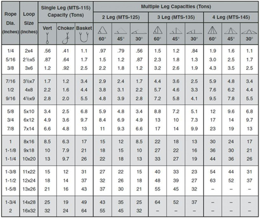
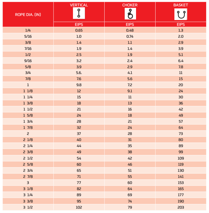
VERTICAL, or straight, attachment is simply using a sling to connect a lifting hook to a load. Full rated lifting capacity of the sling may be utilized, but must not be exceeded. A tagline should be used to prevent load rotation, which may damage a sling.
When two or more slings are attached to the same lifting hook, the total hitch becomes, in effect, a lifting bridle, and the load is distributed equally among the individual slings.
CHOKERhitches reduce lifting capability of a sling since this method of rigging affects ability of the wire rope components to adjust during the lift. A choker is used when the load will not be seriously damaged by the sling body — or the sling damaged by the load, and when the lift requires the sling to snug up against the load.
The diameter of the bend where the sling contacts the load should keep the point of choke against the sling BODY — never against a splice or the base of the eye. When a choke is used at an angle of less than 120 degrees (see next page), the sling-rated capacity must be adjusted downward.
A choker hitch should be pulled tight before a lift is made — NOT PULLED DOWN DURING THE LIFT. It is also dangerous to use only one choker hitch to lift a load which might shift or slide out of the choke.
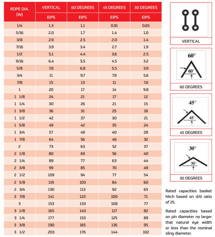
As the included angle between the legs of a sling decreases, the load on each leg increases. The effect is the same whether a single sling is used as a basket or two slings are used with each in a straight pull, as with a 2-legged bridle.
Anytime pull is exerted at an angle on a leg—or legs—of a sling, the load per leg can be determined by using the data in the table above. Proceed as follows to calculate this load—and determine the rated capacity required of the sling, or slings, needed for a lift.First, divide the total load to be lifted by the number of legs to be used. This provides the load per leg if the lift were being made with all legs being vertically.
Then MULTIPLY the load per leg (as computed above) by the Load Factor for the leg angle being used (from the table at the bottom) – to compute the ACTUAL LOAD on each leg for this lift and angle. THE ACTUAL LOAD MUST NOT EXCEED THE RATED SLING CAPACITY.
Thus, in the above drawing (sling angle at 60°): 1000 ÷ 2 = 500 (Load Per Leg if a vertical lift) 500 x 1.154 = 577 lbs. – ACTUAL LOAD on each leg at the 60° included angle being used.
In the above drawing (sling angle of 45°): 1000 ÷ 2 = 500 (Load Per Leg if a vertical lift) 500 x 1.414 = 707 lbs. = ACTUAL LOAD on each leg at the 45° horizontal angle being used.
The horizontal angle of bridles with 3 or more legs is measured the same as the horizontal sling angle of 2-legged hitches. In this case, where a bridle designed with different leg lengths results in horizontal angles, the leg with the smallest horizontal angle will carry the greatest load. Therefore, the smallest horizontal angle is used in calculating actual leg load and evaluating the rated capacity of the sling proposed.
On the other hand, the eye should always be used on a hook or pin with at least the nominal diameter of the rope—since applying the D/d Ratio shows an efficiency loss of approximately 50% when the relationship is less than 1/1.
When rigged as a basket, DIAMETER of the bend where a sling contacts the load can be a limiting factor on sling capacity. Standard D/d ratios— where “D” is the diameter of bend, and “d” the diameter of the rope—are applied to determine efficiency of various sling constructions, as indicated below:Mechanically Spliced, Single-Part Slings: 25 times rope diameter
Whether to use a single-part sling (one made of a single wire rope in the sling body) or a multi-part sling (several ropes in the body) is usually the first decision to make after determining the sling length and capacity for a lift.
The starting point for this decision involves the handling characteristics of the sling more than any other factor. Based on capacity alone, multi-part slings will be more flexible…more easily handled…than single-part slings. The larger the capacity of a sling, the more important this becomes…to the point, it becomes unrealistic to build big capacity slings from single, very large wire ropes.
In the design of the sling, rope engineers must seek a balance between strength-handling characteristics and number of parts…since there is a tendency to lose strength as core parts are added to increase flexibility.
If a load is hanging free, the normal choke angle is approximately 135 degrees. When the angle is less than 135 degrees, an adjustment in the sling-rated capacity must be made. Choker hitches at angles greater than 135 degrees are not recommended since they are unstable.
Extreme care should be taken to determine the angle of choke as accurately as possible. In controlled tests, where the angle was less than 120 degrees, the sling body always failed at the point of choke when pulled to destruction. Allowance for this phenomenon must be made anytime a choker hitch is used to shift, turn or control a load, or when the pull is against the choke in a multi-leg lift.
This is the length of wire rope between splices, sleeves or fittings. Generally, the minimum body length is equal to ten (10) times the sling body diameter. This allows approximately one and one half (1-1/2) rope lays between splices. For Multi-part slings, the minimum body length between splices is equal to forty (40) times the component rope diameter.
1. Turn back the specified amount of rope from the thimble. Apply the first clip one base width from the dead end of the wire rope. Place the U-bolt over the dead end; the live end rests in the clip saddle. Tighten the nuts evenly to the recommended torque.
3. Space additional clips, if required, equally between the first two. Turn on nuts, take up any rope slack, and tighten all nuts evenly to the recommended torque.
4. Apply the initial load and retighten the nuts to recommended torque. The rope will stretch and shrink in diameter when loads are applied. Inspect the clips periodically and retighten. Recommended torque values are based on the threads being clean, dry and free of lubrication.
Loads may slip or fall if proper eye bolt assembly and lifting procedures are not used. Always inspect eye bolts before use and never use eye bolts that show signs of wear or damage. Never use eye bolts if eye or shank is elongated or bent. Be sure all threads are clean. Do not exceed the following working load li
Fibrous and synthetic rope, wire rope and cable must be inspected regularly. No product, even when used in the proscribed manner, can function forever at its rated capacity. The end user must inspect the product frequently for any condition (abrasion, abuse, negligence, normal wear and tear, etc.) which, should the product be left in use, might result in its failure.
Working load is based upon static or moderately dynamic lifting/pulling operations. Instantaneous changes in load, up or down, in excess of 10% of the sling"s rated working load constitutes hazardous shock load, and would void normal working load recommendations.
These products are not designed or recommended for use in the entertainment rigging business, but are offered as a service to our customers who indulge in climbing or similar recreational activities. It is the responsibility of the end user to be properly trained in the inspection, maintenance and use of these products.
DISCLAIMER: This Working Load Limit Chart is provided as a guide only. When preparing lifting calculations please check the relevant Australian Standard.


 8613371530291