
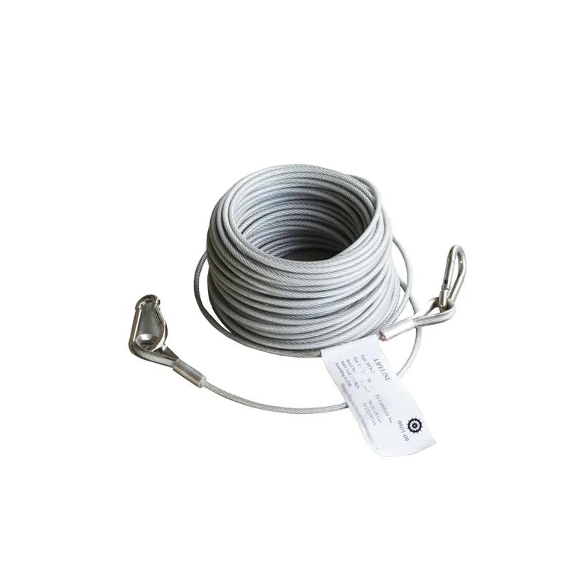
safety lifeline wire rope size free sample

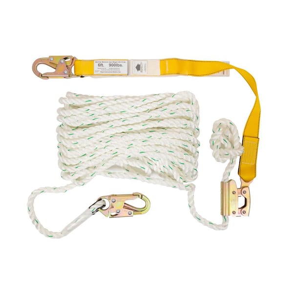
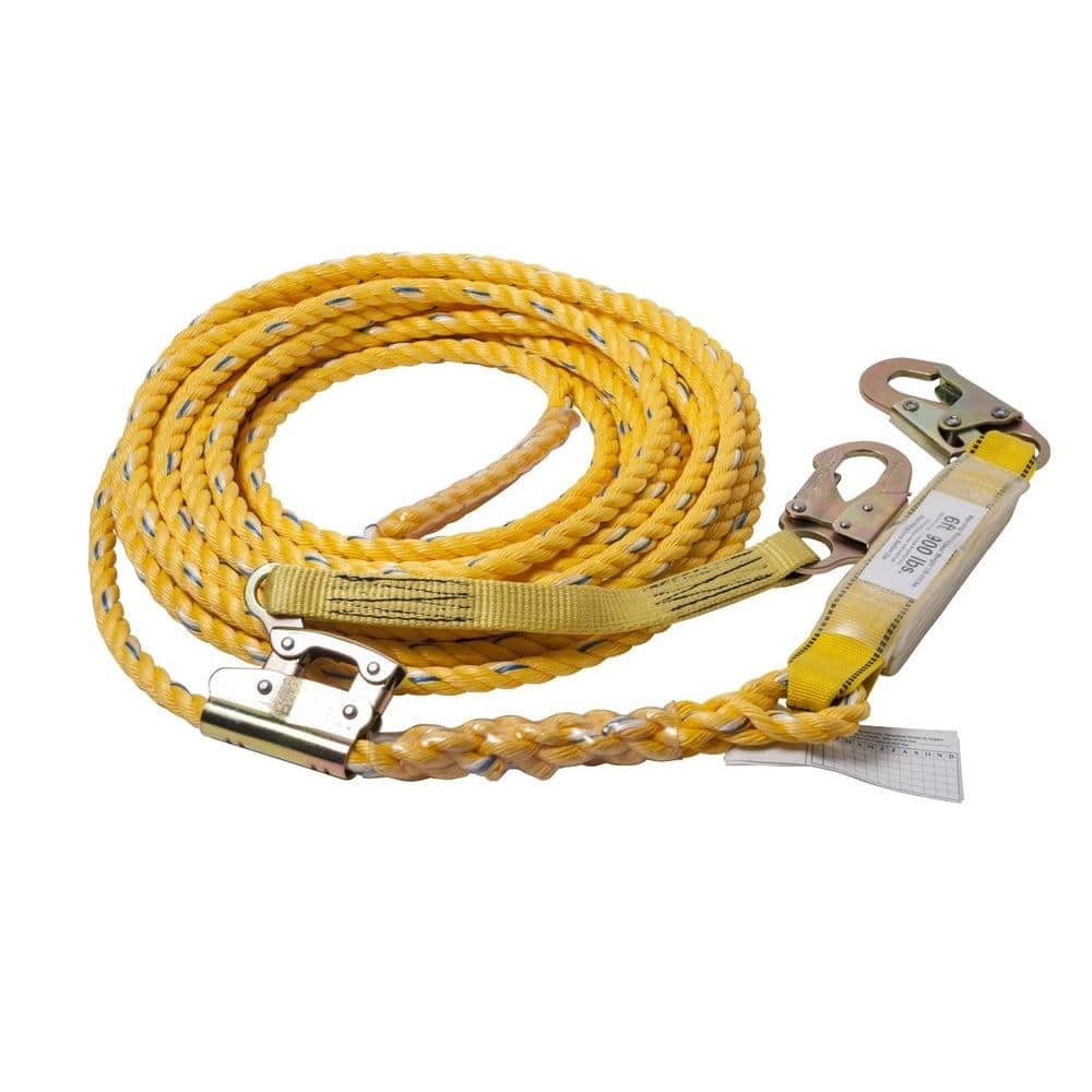
When it comes to any at-height industry, fall protection is an important part of the job. Not to mention you will probably spend some time in situations where tying off to an appropriate anchor can be difficult. That"s why having the best lifeline is important. Our gear experts have spent years sourcing the best lifeline rope available and our hand-picked selection will help you stay safe and get the job done. We feature a range of styles, colors, lengths, and sizes of rope. You can choose a rope from 300, 600, or 1,200 foot pre-cut lengths, or if you need a custom length rope - we’ve got you covered there too. Diameters include ?, 7/16, ?, and ½ inch options and come in a variety of styles including HTP static, 3-strand, and unicore. We’ve also got a range of colors so that each lifeline can be visibly different than the others for easy identification.
(1) Lifelines, lanyards and deceleration devices should be attached to an anchorage and connected to the body-belt or body harness in the same manner as they would be when used to protect employees.
(5) The lanyard or lifeline used to create the free fall distance should be supplied with the system, or in its absence, the least elastic lanyard or lifeline available to be used with the system.
(4) For rope-grab-type deceleration systems, the length of the lifeline above the centerline of the grabbing mechanism to the lifeline"s anchorage point should not exceed 2 feet (0.61 m).
(5) For lanyard systems, for systems with deceleration devices which do not automatically limit free fall distance to 2 feet (0.61 m ) or less, and for systems with deceleration devices which have a connection distance in excess of 1 foot (0.3 m) (measured between the centerline of the lifeline and the attachment point to the body belt or harness), the test weight should be rigged to free fall a distance of 7.5 feet (2.3 m) from a point that is 1.5 feet (.46 m) above the anchorage point, to its hanging location (6 feet below the anchorage). The test weight should fall without interference, obstruction, or hitting the floor or ground during the test. In some cases a non-elastic wire lanyard of sufficient length may need to be added to the system (for test purposes) to create the necessary free fall distance.
(6) For deceleration device systems with integral lifelines or lanyards which automatically limit free fall distance to 2 feet (0.61 m) or less, the test weight should be rigged to free fall a distance of 4 feet (1.22 m).
(A) For deceleration systems which have a connection link or lanyard, the test weight should free fall a distance equal to the connection distance (measured between the centerline of the lifeline and the attachment point to the body belt or harness).
(B) For deceleration device systems with integral lifelines or lanyards which automatically limit free fall distance to 2 feet (0.61 m) or less, the test weight should free fall a distance equal to that permitted by the system in normal use. (For example, to test a system with a self-retracting lifeline or lanyard, the test weight should be supported and the system allowed to retract the lifeline or lanyard as it would in normal use. The test weight would then be released and the force and deceleration distance measured).
(e) "Deceleration device tests." (1) "General." The device should be evaluated or tested under the environmental conditions, (such as rain, ice, grease, dirt, type of lifeline, etc.), for which the device is designed.
(2) "Rope-grab-type deceleration devices." (i) Devices should be moved on a lifeline 1,000 times over the same length of line a distance of not less than 1 foot (30.5 cm), and the mechanism should lock each time.
(ii) Unless the device is permanently marked to indicate the type(s) of lifeline which must be used, several types (different diameters and different materials), of lifelines should be used to test the device.
(a) "Selection and use considerations." (1) The kind of personal fall arrest system selected should match the particular work situation, and any possible free fall distance should be kept to a minimum. Consideration should be given to the particular work environment. For example, the presence of acids, dirt, moisture, oil, grease, etc., and their effect on the system, should be evaluated. Hot or cold environments may also have an adverse effect on the system. Wire rope should not be used where an electrical hazard is anticipated. As required by the standard, the employer must plan to have means available to promptly rescue an employee should a fall occur, since the suspended employee may not be able to reach a work level independently.
(2) Where lanyards, connectors, and lifelines are subject to damage by work operations such as welding, chemical cleaning, and sandblasting, the component should be protected, or other securing systems should be used. The employer should fully evaluate the work conditions and environment (including seasonal weather changes) before selecting the appropriate personal fall protection system. Once in use, the system"s effectiveness should be monitored. In some cases, a program for cleaning and maintenance of the system may be necessary.
(c) "Component compatibility considerations." Ideally, a personal fall arrest system is designed, tested, and supplied as a complete system. However, it is common practice for lanyards, connectors, lifelines, deceleration devices, body belts and body harnesses to be interchanged since some components wear out before others. The employer and employee should realize that not all components are interchangeable. For instance, a lanyard should not be connected between a body belt (or harness) and a deceleration device of the self-retracting type since this can result in additional free fall for which the system was not designed. Any substitution or change to a personal fall arrest system should be fully evaluated or tested by a competent person to determine that it meets the standard, before the modified system is put in use.
(d) "Employee training considerations." Thorough employee training in the selection and use of personal fall arrest systems is imperative. Employees must be trained in the safe use of the system. This should include the following: application limits; proper anchoring and tie-off techniques; estimation of free fall distance, including determination of deceleration distance, and total fall distance to prevent striking a lower level; methods of use; and inspection and storage of the system. Careless or improper use of the equipment can result in serious injury or death. Employers and employees should become familiar with the material in this Appendix, as well as manufacturer"s recommendations, before a system is used. Of uppermost importance is the reduction in strength caused by certain tie-offs (such as using knots, tying around sharp edges, etc.) and maximum permitted free fall distance. Also, to be stressed are the importance of inspections prior to use, the limitations of the equipment, and unique conditions at the worksite which may be important in determining the type of system to use.
(e) "Instruction considerations." Employers should obtain comprehensive instructions from the supplier as to the system"s proper use and application, including, where applicable:
(6) Proper hook-up, anchoring and tie-off techniques, including the proper dee-ring or other attachment point to use on the body belt and harness for fall arrest;
(g) "Inspection considerations." As required by 1926.502(d)(21), personal fall arrest systems must be regularly inspected. Any component with any significant defect, such as cuts, tears, abrasions, mold, or undue stretching; alterations or additions which might affect its efficiency; damage due to deterioration; contact with fire, acids, or other corrosives; distorted hooks or faulty hook springs; tongues unfitted to the shoulder of buckles; loose or damaged mountings; non-functioning parts; or wearing or internal deterioration in the ropes must be withdrawn from service immediately, and should be tagged or marked as unusable, or destroyed.
(h) "Tie-off considerations." (1) One of the most important aspects of personal fall protection systems is fully planning the system before it is put into use. Probably the most overlooked component is planning for suitable anchorage points. Such planning should ideally be done before the structure or building is constructed so that anchorage points can be incorporated during construction for use later for window cleaning or other building maintenance. If properly planned, these anchorage points may be used during construction, as well as afterwards.
(i) Properly planned anchorages should be used if they are available. In some cases, anchorages must be installed immediately prior to use. In such cases, a registered professional engineer with experience in designing fall protection systems, or another qualified person with appropriate education and experience should design an anchor point to be installed.
(ii) In other cases, the Agency recognizes that there will be a need to devise an anchor point from existing structures. Examples of what might be appropriate anchor points are steel members or I-beams if an acceptable strap is available for the connection (do not use a lanyard with a snaphook clipped onto itself); large eye-bolts made of an appropriate grade steel; guardrails or railings if they have been designed for use as an anchor point; or masonry or wood members only if the attachment point is substantial and precautions have been taken to assure that bolts or other connectors will not pull through. A qualified person should be used to evaluate the suitable of these "make shift" anchorages with a focus on proper strength.
(2) Employers and employees should at all times be aware that the strength of a personal fall arrest system is based on its being attached to an anchoring system which does not reduce the strength of the system (such as a properly dimensioned eye-bolt/snap-hook anchorage). Therefore, if a means of attachment is used that will reduce the strength of the system, that component should be replaced by a stronger one, but one that will also maintain the appropriate maximum arrest force characteristics.
(3) Tie-off using a knot in a rope lanyard or lifeline (at any location) can reduce the lifeline or lanyard strength by 50 percent or more. Therefore, a stronger lanyard or lifeline should be used to compensate for the weakening effect of the knot, or the lanyard length should be reduced (or the tie-off location raised) to minimize free fall distance, or the lanyard or lifeline should be replaced by one which has an appropriately incorporated connector to eliminate the need for a knot.
(4) Tie-off of a rope lanyard or lifeline around an "H" or "I" beam or similar support can reduce its strength as much as 70 percent due to the cutting action of the beam edges. Therefore, use should be made of a webbing lanyard or wire core lifeline around the beam; or the lanyard or lifeline should be protected from the edge; or free fall distance should be greatly minimized.
(5) Tie-off where the line passes over or around rough or sharp surfaces reduces strength drastically. Such a tie-off should be avoided or an alternative tie-off rigging should be used. Such alternatives may include use of a snap-hook/dee ring connection, wire rope tie-off, an effective padding of the surfaces, or an abrasion-resistance strap around or over the problem surface.
(6) Horizontal lifelines may, depending on their geometry and angle of sag, be subjected to greater loads than the impact load imposed by an attached component. When the angle of horizontal lifeline sag is less than 30 degrees, the impact force imparted to the lifeline by an attached lanyard is greatly amplified. For example, with a sag angle of 15 degrees, the force amplification is about 2:1 and at 5 degrees sag, it is about 6:1. Depending on the angle of sag, and the line"s elasticity, the strength of the horizontal lifeline and the anchorages to which it is attached should be increased a number of times over that of the lanyard. Extreme care should be taken in considering a horizontal lifeline for multiple tie-offs. The reason for this is that in multiple tie-offs to a horizontal lifeline, if one employee falls, the movement of the falling employee and the horizontal lifeline during arrest of the fall may cause other employees to fall also. Horizontal lifeline and anchorage strength should be increased for each additional employee to be tied off. For these and other reasons, the design of systems using horizontal lifelines must only be done by qualified persons. Testing of installed lifelines and anchors prior to use is recommended.
(7) The strength of an eye-bolt is rated along the axis of the bolt and its strength is greatly reduced if the force is applied at an angle to this axis (in the direction of shear). Also, care should be exercised in selecting the proper diameter of the eye to avoid accidental disengagement of snap-hooks not designed to be compatible for the connection.
(8) Due to the significant reduction in the strength of the lifeline/lanyard (in some cases, as much as a 70 percent reduction), the sliding hitch knot (prusik) should not be used for lifeline/lanyard connections except in emergency situations where no other available system is practical. The "one-and-one" sliding hitch knot should never be used because it is unreliable in stopping a fall. The "two-and-two," or "three-and-three" knot (preferable) may be used in emergency situations; however, care should be taken to limit free fall distance to a minimum because of reduced lifeline/lanyard strength.
(i) "Vertical lifeline considerations." As required by the standard, each employee must have a separate lifeline [except employees engaged in constructing elevator shafts who are permitted to have two employees on one lifeline] when the lifeline is vertical. The reason for this is that in multiple tie-offs to a single lifeline, if one employee falls, the movement of the lifeline during the arrest of the fall may pull other employees" lanyards, causing them to fall as well.
(j) "Snap-hook considerations." (1) Although not required by this standard for all connections until January 1, 1998, locking snaphooks designed for connection to suitable objects (of sufficient strength) are highly recommended in lieu of the nonlocking type. Locking snaphooks incorporate a positive locking mechanism in addition to the spring loaded keeper, which will not allow the keeper to open under moderate pressure without someone first releasing the mechanism. Such a feature, properly designed, effectively prevents roll-out from occurring.
(2) As required by 1926.502(d)(6), the following connections must be avoided (unless properly designed locking snaphooks are used) because they are conditions which can result in roll-out when a nonlocking snaphook is used:
(vi) Improper dimensions of the dee-ring, rebar, or other connection point in relation to the snaphook dimensions which would allow the snaphook keeper to be depressed by a turning motion of the snaphook.
(k) "Free fall considerations." The employer and employee should at all times be aware that a system"s maximum arresting force is evaluated under normal use conditions established by the manufacturer, and in no case using a free fall distance in excess of 6 feet (1.8 m). A few extra feet of free fall can significantly increase the arresting force on the employee, possibly to the point of causing injury. Because of this, the free fall distance should be kept at a minimum, and, as required by the standard, in no case greater than 6 feet (1.8 m). To help assure this, the tie-off attachment point to the lifeline or anchor should be located at or above the connection point of the fall arrest equipment to belt or harness. (Since otherwise additional free fall distance is added to the length of the connecting means (i.e. lanyard)). Attaching to the working surface will often result in a free fall greater than 6 feet (1.8 m). For instance, if a 6 foot (1.8 m) lanyard is used, the total free fall distance will be the distance from the working level to the body belt (or harness) attachment point plus the 6 feet (1.8 m) of lanyard length. Another important consideration is that the arresting force which the fall system must withstand also goes up with greater distances of free fall, possibly exceeding the strength of the system.
(l) "Elongation and deceleration distance considerations." Other factors involved in a proper tie-off are elongation and deceleration distance. During the arresting of a fall, a lanyard will experience a length of stretching or elongation, whereas activation of a deceleration device will result in a certain stopping distance. These distances should be available with the lanyard or device"s instructions and must be added to the free fall distance to arrive at the total fall distance before an employee is fully stopped. The additional stopping distance may be very significant if the lanyard or deceleration device is attached near or at the end of a long lifeline, which may itself add considerable distance due to its own elongation. As required by the standard, sufficient distance to allow for all of these factors must also be maintained between the employee and obstructions below, to prevent an injury due to impact before the system fully arrests the fall. In addition, a minimum of 12 feet (3.7 m) of lifeline should be allowed below the securing point of a rope grab type deceleration device, and the end terminated to prevent the device from sliding off the lifeline. Alternatively, the lifeline should extend to the ground or the next working level below. These measures are suggested to prevent the worker from inadvertently moving past the end of the lifeline and having the rope grab become disengaged from the lifeline.
(n) "Other considerations." Because of the design of some personal fall arrest systems, additional considerations may be required for proper tie-off. For example, heavy deceleration devices of the self-retracting type should be secured overhead in order to avoid the weight of the device having to be supported by the employee. Also, if self-retracting equipment is connected to a horizontal lifeline, the sag in the lifeline should be minimized to prevent the device from sliding down the lifeline to a position which creates a swing hazard during fall arrest. In all cases, manufacturer"s instructions should be followed.
When used in combination with personal protective equipment, a horizontal lifeline can arrest a fall, limiting the amount of force that is transferred both to the worker and the fall arrest system. This same combination of horizontal lifeline, body harness, and lanyard can also serve as a fall restraint system, limiting the the worker’s ability to move close enough to fall over an unprotected leading edge. The fall restraint and fall arrest properties of horizontal lifelines make the HLL an integral part of many fall protection systems.
Diversified Fall Protection a complete turnkey provider of OSHA compliant horizontal lifeline systems. Contact us for expert assistance with your fall arrest, fall restraint and fall protection requirements

(b) Selection and use considerations. (1) The kind of personal fall protection system selected should be appropriate for the employee"s specific work situation. Free fall distances should always be kept to a minimum. Many systems are designed for particular work applications, such as climbing ladders and poles; maintaining and servicing equipment; and window cleaning. Consideration should be given to the environment in which the work will be performed. For example, the presence of acids, dirt, moisture, oil, grease, or other substances, and their potential effects on the system selected, should be evaluated. The employer should fully evaluate the work conditions and environment (including seasonal weather changes) before selecting the appropriate personal fall protection system. Hot or cold environments may also affect fall protection systems. Wire rope should not be used where electrical hazards are anticipated. As required by § 1910.140(c)(21), the employer must provide a means for promptly rescuing an employee should a fall occur.
(2) Where lanyards, connectors, and lifelines are subject to damage by work operations, such as welding, chemical cleaning, and sandblasting, the component should be protected, or other securing systems should be used. A program for cleaning and maintaining the system may be necessary.
(d) Component compatibility considerations. Ideally, a personal fall protection system is designed, tested, and supplied as a complete system. However, it is common practice for lanyards, connectors, lifelines, deceleration devices, body belts, and body harnesses to be interchanged since some components wear out before others. Employers and employees should realize that not all components are interchangeable. For instance, a lanyard should not be connected between a body harness and a deceleration device of the self-retracting type (unless specifically allowed by the manufacturer) since this can result in additional free fall for which the system was not designed. In addition, positioning components, such as pole straps, ladder hooks and rebar hooks, should not be used in personal fall arrest systems unless they meet the appropriate strength and performance requirements of part 1910 (e.g., §§ 1910.140, 1910.268 and 1910.269). Any substitution or change to a personal fall protection system should be fully evaluated or tested by a competent person to determine that it meets applicable OSHA standards before the modified system is put in use. Also, OSHA suggests that rope be used according to manufacturers" recommendations, especially if polypropylene rope is used.
(e) Employee training considerations. As required by §§ 1910.30 and 1910.132, before an employee uses a fall protection system, the employer must ensure that he or she is trained in the proper use of the system. This may include the following: The limits of the system; proper anchoring and tie-off techniques; estimating free fall distance, including determining elongation and deceleration distance; methods of use; and inspection and storage. Careless or improper use of fall protection equipment can result in serious injury or death. Employers and employees should become familiar with the material in this standard and appendix, as well as manufacturers" recommendations, before a system is used. It is important for employees to be aware that certain tie-offs (such as using knots and tying around sharp edges) can reduce the overall strength of a system. Employees also need to know the maximum permitted free fall distance. Training should stress the importance of inspections prior to use, the limitations of the equipment to be used, and unique conditions at the worksite that may be important.
(f) Instruction considerations. Employers should obtain comprehensive instructions from the supplier or a qualified person as to the system"s proper use and application, including, where applicable:
(1) Tie-off using a knot in the lanyard or lifeline (at any location). The strength of the line can be reduced by 50 percent or more if a knot is used. Therefore, a stronger lanyard or lifeline should be used to compensate for the knot, or the lanyard length should be reduced (or the tie-off location raised) to minimize free fall distance, or the lanyard or lifeline should be replaced by one which has an appropriately incorporated connector to eliminate the need for a knot.
(2) Tie-off around rough or sharp (e.g., “H” or “I” beams) surfaces. Sharp or rough surfaces can damage rope lines and this reduces strength of the system drastically. Such tie-offs should be avoided whenever possible. An alternate means should be used such as a snaphook/D-ring connection, a tie-off apparatus (steel cable tie-off), an effective padding of the surfaces, or an abrasion-resistant strap around the supporting member. If these alternative means of tie-off are not available, the employer should try to minimize the potential free fall distance.
(3) Knots. Sliding hitch knots should not be used except in emergency situations. The one-and-one sliding hitch knot should never be used because it is unreliable in stopping a fall. The two-and-two, or three-and-three knots (preferable) may be used in emergency situations; however, care should be taken to limit free fall distances because of reduced lifeline/lanyard strength. OSHA requires that a competent or qualified person inspect each knot in a lanyard or vertical lifeline to ensure it meets the strength requirements in § 1910.140.
(j) Horizontal lifelines. Horizontal lifelines, depending on their geometry and angle of sag, may be subjected to greater loads than the impact load imposed by an attached component. When the angle of horizontal lifeline sag is less than 30 degrees, the impact force imparted to the lifeline by an attached lanyard is greatly amplified. For example, with a sag angle of 15 degrees the force amplification is about 2:1, and at 5 degrees sag it is about 6:1. Depending on the angle of sag, and the line"s elasticity, the strength of the horizontal lifeline, and the anchorages to which it is attached should be increased a number of times over that of the lanyard. Extreme care should be taken in considering a horizontal lifeline for multiple tie-offs. If there are multiple tie-offs to a horizontal lifeline, and one employee falls, the movement of the falling employee and the horizontal lifeline during arrest of the fall may cause other employees to fall. Horizontal lifeline and anchorage strength should be increased for each additional employee to be tied-off. For these and other reasons, the systems using horizontal lifelines must be designed only by qualified persons. OSHA recommends testing installed lifelines and anchors prior to use. OSHA requires that horizontal lifelines are designed, installed and used under the supervision of a qualified person.
(k) Eye-bolts. It must be recognized that the strength of an eye-bolt is rated along the axis of the bolt, and that its strength is greatly reduced if the force is applied at right angles to this axis (in the direction of its shear strength). Care should also be exercised in selecting the proper diameter of the eye to avoid creating a roll-out hazard (accidental disengagement of the snaphook from the eye-bolt).
(l) Vertical lifeline considerations. As required by § 1910.140(c)(3), each employee must have a separate lifeline when the lifeline is vertical. If multiple tie-offs to a single lifeline are used, and one employee falls, the movement of the lifeline during the arrest of the fall may pull other employees" lanyards, causing them to fall as well.
(5) Improper dimensions of the D-ring, rebar, or other connection point in relation to the snaphook or carabiner dimensions which would allow the gate to be depressed by a turning motion.
(n) Free fall considerations. Employers and employees should always be aware that a system"s maximum arresting force is evaluated under normal use conditions established by the manufacturer. OSHA requires that personal fall arrest systems be rigged so an employee cannot free fall in excess of 6 feet (1.8 m). Even a few additional feet of free fall can significantly increase the arresting force on the employee, possibly to the point of causing injury and possibly exceeding the strength of the system. Because of this, the free fall distance should be kept to a minimum, and, as required by § 1910.140(d)(2), must never be greater than 6 feet (1.8 m). To assure this, the tie-off attachment point to the lifeline or anchor should be located at or above the connection point of the fall arrest equipment to the harness. (Otherwise, additional free fall distance is added to the length of the connecting means (i.e., lanyard)). Tying off to the walking-working surface will often result in a free fall greater than 6 feet (1.8 m). For instance, if a 6-foot (1.8-m) lanyard is used, the total free fall distance will be the distance from the walking-working level to the harness connection plus the 6 feet (1.8 m) of lanyard.
(o) Elongation and deceleration distance considerations. During fall arrest, a lanyard will stretch or elongate, whereas activation of a deceleration device will result in a certain stopping distance. These distances should be available with the lanyard or device"s instructions and must be added to the free fall distance to arrive at the total fall distance before an employee is fully stopped. The additional stopping distance may be significant if the lanyard or deceleration device is attached near or at the end of a long lifeline, which may itself add considerable distance due to its own elongation. As required by § 1910.140(d)(2), sufficient distance to allow for all of these factors must also be maintained between the employee and obstructions below, to prevent an injury due to impact before the system fully arrests the fall. In addition, a minimum of 12 feet (3.7 m) of lifeline should be allowed below the securing point of a rope-grab-type deceleration device, and the end terminated to prevent the device from sliding off the lifeline. Alternatively, the lifeline should extend to the ground or the next working level below. These measures are suggested to prevent the employee from inadvertently moving past the end of the lifeline and having the rope grab become disengaged from the lifeline.

CAB Lifeline is an emergency escape line designed to help evacuate an underground mine in the event of fire or explosion. Since 1985, the CAB Lifeline has been hand crafted to rigid standards of quality and performance. It is available in rope and heavy-duty aircraft cable styles to meet the wide variety of requirements found in the underground mining industry.
CAB Lifelinemeets all state and federal regulations and is accepted by MSHA under Part 18, Title 30 Code of Federal Regulations. Research by NIOSH and the U.S. Bureau of Mines confirms that use of Lifeline can significantly improve chances for successful escape when fire breaks out in an underground mine.
CAB Extra High Visibility Lifeline is easily seen from any direction in escapeways. Lifeline markers hang vertically so they can be seen for long distances up and down escapeways. Markers are flexible so miners’ hands can slide easily over them.
CAB Lifeline is hand crafted to rigid quality standards. Available in rope and heavy duty aircraft cable styles. Lifeline sections quickly and securely lock together with heavy duty aircraft cable oval sleeves, thimbles and quick links. CAB Rope Lifeline is manufactured from 1/4″ (6.4mm) diameter, yellow, flame retardant polypropylene rope. Available in 300′ (91.4m) and 1,000′ (304.8m) spools.
CAB Heavy-Duty Aircraft Cable Lifeline (patent pending) is much more durable, especially in case of mine fires, explosions or rock falls. Made from strong 3/16” (5mm) diameter plastic coated, galvanized aircraft cable for maximum durability and safety. Sold in 300′ (91.4m) spools.
CAB Extra High Visibility Lifeline features the most brilliant reflective markers in the industry. Markers are firmly attached to Lifeline and can’t break or fall off like other reflectors.
CAB Lifeline is offered in standard and extra-high visibility styles. CAB Standard Lifeline has 2” (51mm) wide reflective tape bands wrapped around the Lifeline at 25 foot (7.6m) intervals between cones. CAB Extra High Visibility Lifeline meets heightened safety standards with reflective markers suspended vertically at 25 foot (7.6m) intervals between cones, as pictured above.
CAB’s brilliant extra high visibility markers can be easily seen from any direction in the escapeway. Because of their firm attachment to the Lifeline with aluminum stop sleeves, these reflectors stay oriented to show proper direction of escape at all times.
CAB’s flexible retroreflective vinyl markers are the most brilliant on the market. They are sturdy and won’t crack, shatter or fall off the Lifeline as hard plastic reflectors do.
Available in 2″ x 4″ (51mm x 102mm) size as pictured above or in double length 2″ x 8″ (51mm x 203mm). Can be reflective on one or both sides in the same or different colors.
CAB Directional Cones have 6 reflective bands for high visibility. All cones are securely fastened to Lifeline with aircraft cable hardware. Cannot be accidentally dislodged or removed. Reflective bands available on entire surface or tapered surface only.
CAB Directional Indicators are molded in large, heavy-duty solid cones. The cone size and shape is specifically designed to quickly identify proper direction of travel and to prevent a handgrip from being broken when in actual use. CAB Lifeline is hand constructed under rigid quality control by feeding Lifeline through the center of all cones. Cones are then firmly attached to the Lifeline with aircraft cable hardware. This construction prevents directional cones from being dislodged, tampered with or removed from the Lifeline. Other lifelines on the market use small cones that make it hard to tell proper direction of travel or cones that easily unsnap and fall off, even in normal use.
CAB Split Cones are identical to standard cones except featuring a pre-engineered hole and slit on one side for easy and secure attachment to previously installed Lifeline. Use two cones on main Lifeline to mark all branch lines. Use four cones, forming two diamond shapes on branch lines, to indicate SCSR storage caches. Sold in kits of 10 cones and 20 stop sleeves.
CAB Lifeline Balls are used for marking location of mine personnel doors. Solid and durable, yet lightweight. Firm, secure attachment features a pre-engineered hole and slit on one side for quick, easy installation. Sold in kits of 10 balls and 20 stop sleeves.
CAB Spiral Coil Rumble Strips are used on branch lines that lead to refuge alternative. Strips measure 2″ x 8″ (51mm x 203mm) and are easily threaded into strands of existing Rope Lifeline or can be attached with cable ties to Aircraft Cable or Rope Lifeline.
Rope and Aircraft Cable Hangers quickly attach to lifeline and have a strong hook for attachment to plates, mesh or roof structure. Elastic hangers are especially useful in crosscuts; they stretch five times their original length to lower lifeline during use and return it to original height after use. Quick-Release Hangers have a release pin that attaches to hanger hole or edge of plate. They can be quickly pulled off plates to drop lifeline for emergency escape.
CAB Lifeline with interchangeable Velcro Markers is designed for mines that change color of Lifeline after longwall operations. Made from strong polypropylene webbing with velcro on one side. High visibility 2″ x 6″ (51mm x 152mm) reflective markers with velcro backer (sold separately) are quick and easy to attach and change later to another color as mining progresses and escape routes change.
CAB Tie-On Markers can be easily added to existing Lifeline. Made from 2″ x 4″ (51mm x 102mm) brilliant retroreflective vinyl. Stitched on all sides. Strong nylon cord is sewn into top hem for securely tying markers to Lifeline.
CAB Lifeline requires no assembly and is ready to install. All parts are integral and securely attached with aircraft cable hardware. Lower in overall cost compared to other brands that require stocking of parts and extra labor for assembly.
Full size posters (24 inch x 40 inch) are available free of charge for your mine safety training program. For smaller posters (8.5 x 14 inch legal size ) which you can download and print, click on poster image above.

Harness Land has both temporary and permanent horizontal lifelines. Temporary horizontal lifelines are the ideal solution that combines a lightweight system that is portable to take to every job. They are portable and reusable for an economical choice for fall protection. You’ll find kits with a variety of accessory options to make your product fit the job and its particular requirements. You’ll appreciate the flexibility of being to customize your horizontal lifelines at an affordable price while not sacrificing the safety of you or your workers. The Protecta PRO-Line Temporary Horizontal Lifeline include two tie-off adaptors for simple anchorage to an anchor point. It’s an affordable and versatile choice for a temporary system. It includes a built-in shock absorber and a visual impact indicator. The easy to install system helps you get set up and on the job quickly. For a greater range of applications, the Portable Web Horizontal Lifeline is a two-person system that includes cross-arm straps, snap hooks for structural connection, movable D-rings for lanyard connection, and a ratchet-type web tensioner to give your crew the flexibility to match fall protection needs to the work site. It’s a smart choice for the contractor who works on a variety of jobs.
Harness Land offers several permanent horizontal lifelines solutions when you need a system to stay in place for follow up work and maintenance. Our product line includes the Sayfline Permanent Multi-Span Horizontal Lifeline Systems that comes in lengths from 20 to 180 feet to match your workplace. You can create customizable multi-span configurations with all the necessary mounting hardware, bypassable intermediate brackets, and Zorbit energy absorber to limit the impact of stopped falls. They are available in both stainless steel and multi-span cable horizontal lifeline systems.
Our line also includes the SecuraSpan Pour-in-Place Horizontal Lifeline Systems in 20 to 60 feet lengths. These systems provide overhead horizontal mobility in concrete construction jobs. They have two posts, concrete sleeve and cable assembly with a galvanized cable lifeline and a Zorbit energy absorber.
Harness Land’s product line includes the SecuraSpan Loop Rebar Horizontal Lifeline Systems for lengths from 20 to 60 feet for concrete loop rebar. The systems include two stanchions and lifeline assembly that will fit ½ to 4 ½ inch diameter loop rebar. You can customize it to fit your specifications with accessories and additional components.
The SecuraSpan I-Beam Horizontal Lifeline Systems come in sizes from 20 to 60 feet that will fit 6 to 12 inch wide and up to 2 ¼ inch thick I-beam flanges. The systems use a simple clamp and wing nut installation. They come complete with a galvanized cable lifeline, two stanchions, and cable assembly. Like our other horizontal lifeline systems, you can customize your setup with additional accessories and component.
Harness Land strives to be your one-stop site for all of your fall protection needs that serve all types of jobs. The SecuraSpan Rebar/Shear Stud Horizontal Lifeline System are another example of the right solution for your job. Like other products in the SecuraSpan line, you’ll find systems of different lengths with numerous configurations possible.
Harness Land offers the Sayfline line of Synthetic Horizontal Lifeline Systems and Cable Horizontal Lifeline Systems in a broad range of lifeline lengths for a lightweight and portable fall protection system to accommodate two crew members. The synthetic systems include a tensioner, energy absorber, and two six-foot tie-off adaptors with a kernmantle rope horizontal lifeline. The cable systems come with a galvanized cable lifeline, wedgegrip termination, turnbuckle tensioner and a Zorbit energy absorber. You can choose the length and type to fit your job’s needs.
Our selection of horizontal lifelines would not be complete without the Horizontal Absorbinator Lifeline systems in both over and under 60 feet. They offer maximum flexibility with many configurations. Each system includes cross arm straps, CB Anchors, column and ceiling mounting functionality, and much more to meet the requirements of any application. Horizontal lifelines offer a way to provide optimal fall protection for you and your crew at sites where passive protection isn’t possible. They provide your workers with the flexibility and mobility to perform their jobs in a productive manner while ensuring their safety. Harness Lands offers a complete line of systems that serve a broad range of applications. Whether it is a roofing job or concrete construction work, we have a solution to fit your needs and budget. With the ability to create customized configurations, you can be sure that your crew will be safe no matter where the job takes you.
• Then, add a safety factor of 3 ft. to allow for the possibility of an improperly fit harness, a taller than average worker and/or a miscalculation of distance.
°Using a Retractable Lifeline• First, add the maximum free fall distance (2 ft.) with a retractable lifeline to the maximum deceleration distance (3-1/2 ft.) to the average height of a worker (6 ft.).
• Then, add a safety factor of 3 ft. to allow for the possibility of an improperly fit harness, a taller than average worker and/or a miscalculation of distance.
† NOTE: When using a retractable lifeline, the distance is calculated from the point where the retractable attaches to the back D-ring of the worker’s harness.


 8613371530291