
seismic wire rope free sample

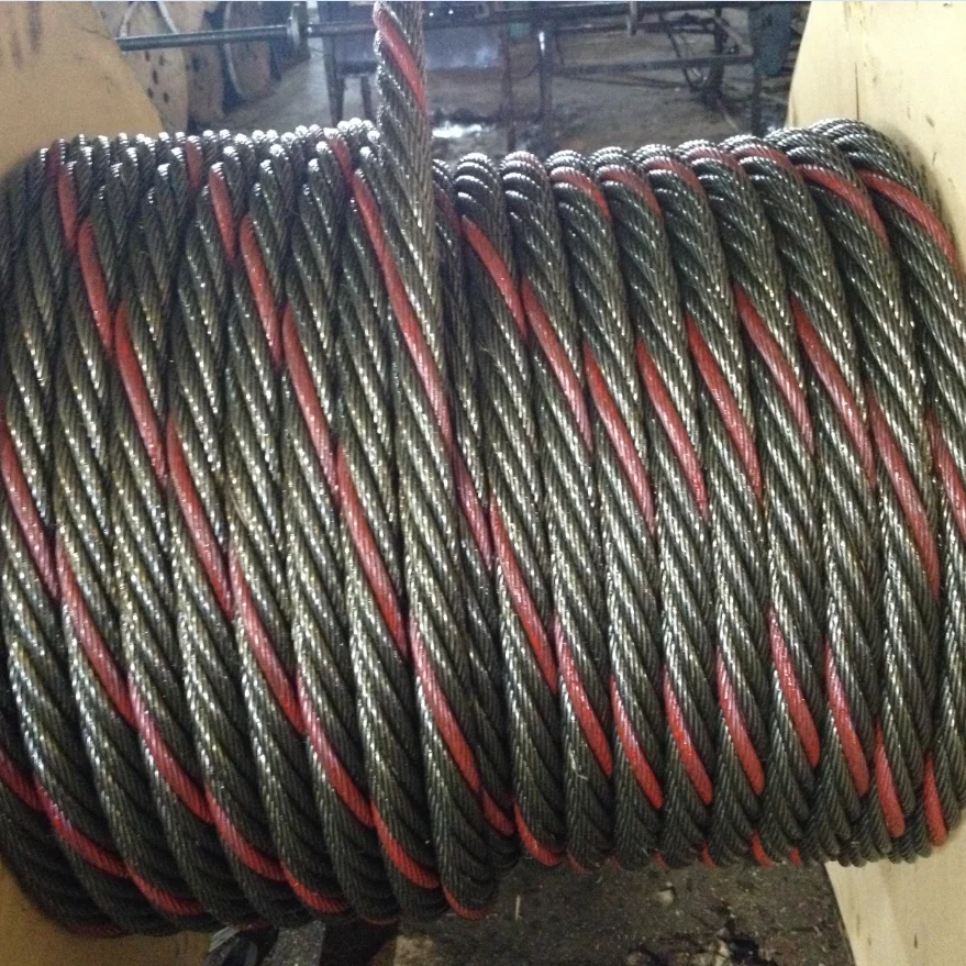
The next generation of wire rope suspension products designed for the fast suspension of cable containment, pipework, ductwork, HVAC systems and modules, including multi-tier installations.
The next generation of wire rope suspension products designed for the fast suspension of cable containment, pipework, ductwork, HVAC systems and modules, including multi-tier installations.
The next generation of wire rope suspension products designed for the fast suspension of cable containment, pipework, ductwork, HVAC systems and modules, including multi-tier installations.
The next generation of wire rope suspension products designed for the fast suspension of cable containment, pipework, ductwork, HVAC systems and modules, including multi-tier installations.
The next generation of wire rope suspension products designed for the fast suspension of cable containment, pipework, ductwork, HVAC systems and modules, including multi-tier installations.
The next generation of wire rope suspension products designed for the fast suspension of cable containment, pipework, ductwork, HVAC systems and modules, including multi-tier installations.
The next generation of wire rope suspension products designed for the fast suspension of cable containment, pipework, ductwork, HVAC systems and modules, including multi-tier installations.
This invention relates to bracing of piping, ductwork and other structural features of buildings and is more particularly directed to apparatus intended primarily for use with tensioned cable sway control systems through use of a single configuration bracket which can be effectively and economically used with a variety of objects to be braced in a variety of cable systems, particularly those providing lateral, longitudinal and four-way sway bracing systems. The invention finds significant usage in bracing structural elements to control seismic induced object sway in earthquake conditions.
Because of the random occurrence of seismic shock waves (earthquakes) and the resulting high damage to property and life, Congress enacted Public Law 95-124 known as the Earthquake Hazards Reduction Act, which act has been amended and made the subject of presidential executive orders. A federal government interagency committee on seismic security in construction has been establishing standards not only for the retrofitting of existing buildings but also standards for new construction intended to reduce damage in the event of an earthquake to the components of life safety systems such as sprinkler systems, electrical distributions systems, piping for various purposes and in general to develop seismic restraint requirements for use by architects, engineers and seismologists.
It is a primary object of this invention to provide a universal restraint bracket having a structure and configuration that makes it suitable for simplified use in a cable tension system for dampening and sway reduction under seismic load conditions.
It is a further object of this invention to provide a restraint bracket or clip suitable for securement to a structural element such as a building wall or ceiling, to objects such as water pipes, electrical conduit, HVAC systems as well as their conventional supports and other apparatus used within the building to facilitate attachment of a cable system to dampen seismic shock induced apparatus sway.
The foregoing objects as well as other objects are achieved by this invention through utilization of a universal one piece restraint bracket which is particularly suited for use with wire rope seismic bracing systems. The universal bracket can be characterized as being generally L-shaped in top plan view to define a flattened apertured central portion with two wing portions arranged generally at right angles to each other and apertured at their free ends as well as being joined to the flattened central portion. Each such wing is upwardly bent away from the plane of the flattened central portion. The flattened centrally apertured portion can be affixed to either a supporting structure or to the device which is to be subjected to dampening forces in the event of forces such seismic loads; the brackets may be identical as the user may desire and can be sized depending upon the nature of the apparatus to be stabilized.
A better understanding of the objects, advantages, features, properties and relations of the invention will be obtained from the following detailed description and accompanying drawings which set forth certain illustrative embodiments and are indicative of the various ways in which the principles of the invention are employed.
Before examining the details of the present invention, it is believed helpful to an understanding the present invention if the nature and status of typical prior art relating to shock bracing, particularly seismic shock bracing, are examined. Consideration of the prior art shown in the drawings is believed essential to an understanding of the problems solved by the present invention. Sway bracing systems to control object sway under, for example, seismic shock conditions have resulted in the preferred prior art use of tensioned cable systems to provide lateral and longitudinal or four-way tensioned cable sway control. Certain fundamental cable concepts have been drawn from the prior art, particularly the marine field, and a fundamental unit is found in FIGS. 1 and 1A. Threaded fastener 10 extends through a suitable washer 11 and bracket 12 having an aperture 14. Bracket 12 may be secured to an object whose sway is to be controlled or to the support structure (not shown) by fastener 10. Cable 18 is of any suitable length and may have brackets such as at 12 at each cable end. Bracket 12 (see particularly FIG. 1A) is provided with an upwardly extending leg or wing 16 from a flat portion 17 of bracket 12. Wing 16 is provided with a suitable aperture 15 to accept cable 18 having a free end wrapped about a thimble 20 extending through aperture 15 with the cable end 22 being trained about thimble 20 and secured to the main cable portion by a suitable crimped fitting 24. This basic structure is a fundamental arrangement for tension sway bracing in the prior art.
In each of the foregoing prior art examples, a single clip or bracket 12 is utilized to affix a cable to the object to be braced. A single aperture is provided in the bracket to accept one or more cable ends, and the resulting stresses imposed on brackets 12 by plural cable bracing techniques creates structural load points of reduced strength to resist the bracing loads, e.g., under a typical seismic sway load situation.
It will be appreciated that there is only a single cable attached to each wing so as to better distribute the load and by virtue of the disclosed angular relationship of the wings 54,56, reduce stresses. As best seen in FIG. 5, wings 54 and 56 are upwardly bent away from the central flat portion or base 52 for optimal cable attachment. The bracket 50 is typically manufactured in bolt hole sizes to accommodate 1/4 inch through 11/4 inch bolts. The cable attachment wings 54,56 are normally capable of receiving size 12, size 18 or size 36 seismic wire rope/cable bracing. Moreover, to minimize undesired prying action of the bracket 50 when it is attached to a support structure and under stress, the cable apertures 60,62 are designed to be closer to the central bolt aperture 58 than in the prior art single clip.
To provide the availability of a plurality of types of cable sway bracing (including lateral and longitudinal or four-way), an installer of sway bracing structure needs only a supply of brackets of this invention for attachment of cable earthquake sway bracing in multiple sway brace configurations without changing the bracket. The bracket shown in FIGS. 4 and 5 is constructed so that the main mounting hole 58 can be used with only a single sway bracing cable secured to the aperture 60 in its one wing 54 or, if desired and as seen in the drawings, wing 56 projects at about a 90° angle relative to wing 54 and is provided with an additional aperture 62 to accept an additional sway bracing cable. Thimbles and cables, with properly crimped fittings, are to be understood to be used to extend from the aperture 60 and 62 in each wing 54 and 56 to a support structure surface with but one cable preferably secured to each wing.
By forming brackets 50 of a material softer than the steel wire cable, the thimble may be dispensed with and an installer then may crimp an oval sleeve at any desired point along the cable. It will be appreciated by those skilled in the art that the universal restraint bracket of this invention is significantly lighter, smaller and less expensive to make than two single clips. These advantages are further amplified by providing for easier field installation at either a support structure or suspended component. In addition, a single universal restraint bracket 50 is particularly convenient in certain applications using bolts, e.g., of a given length which are too short to accommodate double stacked single clip arrangements.


 8613371530291