
shock loading wire rope free sample

MLA style: "Understanding shock loads.." The Free Library. 2013 United States Institute for Theatre Technology, Inc. 10 Dec. 2022 https://www.thefreelibrary.com/Understanding+shock+loads.-a0332379147
Chicago style: The Free Library. S.v. Understanding shock loads.." Retrieved Dec 10 2022 from https://www.thefreelibrary.com/Understanding+shock+loads.-a0332379147
APA style: Understanding shock loads.. (n.d.) >The Free Library. (2014). Retrieved Dec 10 2022 from https://www.thefreelibrary.com/Understanding+shock+loads.-a0332379147
Plug in the values in the following example: load = 200 pounds, falling distance = 12 inches, area factor = 0.472, diameter of rope = 0.25 inches, metallic area = 0.0295 inches^2, modulus of elasticity = 15,000,000 pounds per square inch, and length of cord = 10 feet (120 inches). Therefore, in this example, shock load = 200 x [1 + (1 + (2 x 12 x 0.0295 x 15,000,000)/(200 x 120))^1/2].
Calculate the numerator then the denominator separately, as per the order of operations. So in this example, the equation simplifies to shock load = 200 x [1 + (1 + (10,620,000)/(24,000))^1/2].
Divide the numerator by the denominator, as per the order of operations. So now you have shock load = 200 x [1 + (1 + 442.5)^1/2]. Add 442.5 to 1 within the parentheses to get shock load = 200 x [1 + (443.5)^1/2].

To understand shock forces you must know that there exists static (not in motion) forces, and dynamic (in motion) forces. In the real world we rarely have just simply static forces occurring during lifts. Even small amounts of speeding up or slowing down of the load result in dynamic loads. The very act of even slow lifting often results in some forces caused by movement such as swinging and drifting.
However, the force we are talking about it the one that occurs rapidly as opposed to slow dynamic forces. Shock force is more commonly referred to as shock load. This derives from the fact that engineers routinely refer to forces occurring in and on structural members as loads. In rigging a load is an object to be lifted or flown from one point to another point, hence the use of the phrase shock force in this article.
Shock forces can occur for any number of reasons, most notably; an operator taking up sling slack with a sudden jerk, the rapid acceleration or deceleration of the load, failure of fair leads or sheave guides to prevent the rolling out of a slack line.
The magnitude of a shock force can be many times that of the weight of the load be lifted. This is why the safe working load of rigging equipment is substantially lower than the minimum breaking strength. Minimum breaking strengths are stated for static, straight pulls. A factor of safety must therefore exist.
The amount of force created in a shock situation is dependent on, among other things, the weight of the load and the distance of travel. The exact determination can be quite complicated because the value of the load"s stopping distance is based on the amount of elastic stretch.
In order to precisely calculate the stopping distance we would need to know the exact composition of the wire rope, the equivalent cross sectional area, and the apparent modulus of elasticity of the wire rope composite, and then use a complicated formula to calculate the exact amount of elastic stretch*.
Many manufacturer"s websites state that there exists no practical method to estimate shock force. Gelrum** provides an example of a 75 foot long (L) 1⁄4 inch diameter galvanized cable sling subjected to a shock force by the sudden dropping of a 500 pound load 6 inches. The resulting shock force is 2,296 pounds, a value over 4 times the weight of the load!
*A free applet, or automated calculator, for wire rope elastic stretch is located online at:http://www.macwhyte.com/Technical/Metallic-Area-Elastic-Stretch-Calculator
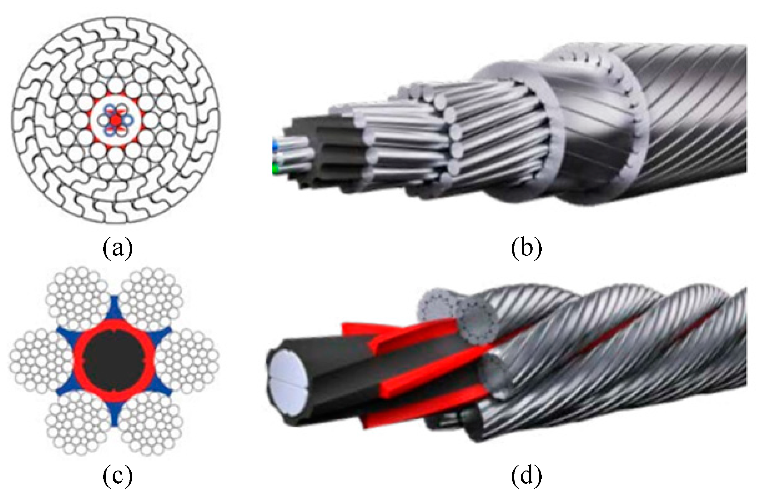
Rope Services Direct supplies a variety of anti-spin non rotating wire rope (also called rotation resistant wire-rope). All standard rope wirehas a tendency to develop torque and therefore prone to rotation, whereas non-rotating wire ropes are designed so that the wire-rope outer rotational force naturally counteracts the inner strands rotational force. This is in the event that a rope is subjected to a load.
Rope elongation and rotation occurs on standard ropes when loaded, which can therefore spin the load, quite possibly out of control, which can be dangerous. When the rope rotates in this way the strands will begin to unravel. This causes the rope to lose strength and will undoubtedly fail, which could be catastrophic. It is for these reasons that non rotating wire rope is commonly used for many types of lifting applications including main hoist rope, whip rope,crane rope, off-shore and deck rope and more.
Non rotating wire rope or rotation resistant wire rope has a different construction to standard. as wires and strands are not laid in the same direction like they would be on standard rope. Inner and outer strands of wires are laid in opposite directions. For example the inner may be constructed in left hand lay whilst the outer layer is in right hand lay. The nature of this construction means that torsional forces on the inner and outer wires/strands will counteract each other and therefore minimising the risk of unraveling.
It is worth noting that the number of strand layers will have an effect of the resistance of rotation. A 2 layer rope has less resistance than a 3 layer rope. Therefore the more layers the rope has the greater rotation resistance it will have.
These types of ropes can be classified as spin resistant, rotation resistant or non rotation resistant. Classed on the basis of the number of rotations a certain length of rope does when a force of 20% of the MBF is applied; with 1 turn or less the rope will be classified as non rotating; with rotations between 1 & 4 the rope is classed as low rotation and for rotations between 4 & 10 the rope will be classified as spin resistant, any higher and the rope is NOT rotation resistant at all.
Correct usage and care with handling will prolong the working life. This is due to the friction on the inner wires caused by the strand crossover’s which will eventually cause the inner wires to break up. This is more apparent on non rotating wire rope with two layers. Ropes with 3 or more strand layers will distribute the radial pressures more evenly. Which will reduce friction and stress on the inner wires.
Regular,thorough inspectionsof non rotating rope are essential due to the fact that it is the inner strands that often break first and broken internal wires often go unnoticed as they are difficult to see.Rope Services Direct offer inspectionson all rope with certification issued on completion.
Holding both ends of the rope will prevent unraveling. Correctly fitted terminations will help to prevent damage. Kinking and unraveling may occur and they can also have an effect on the rotational balance if not fitted correctly.
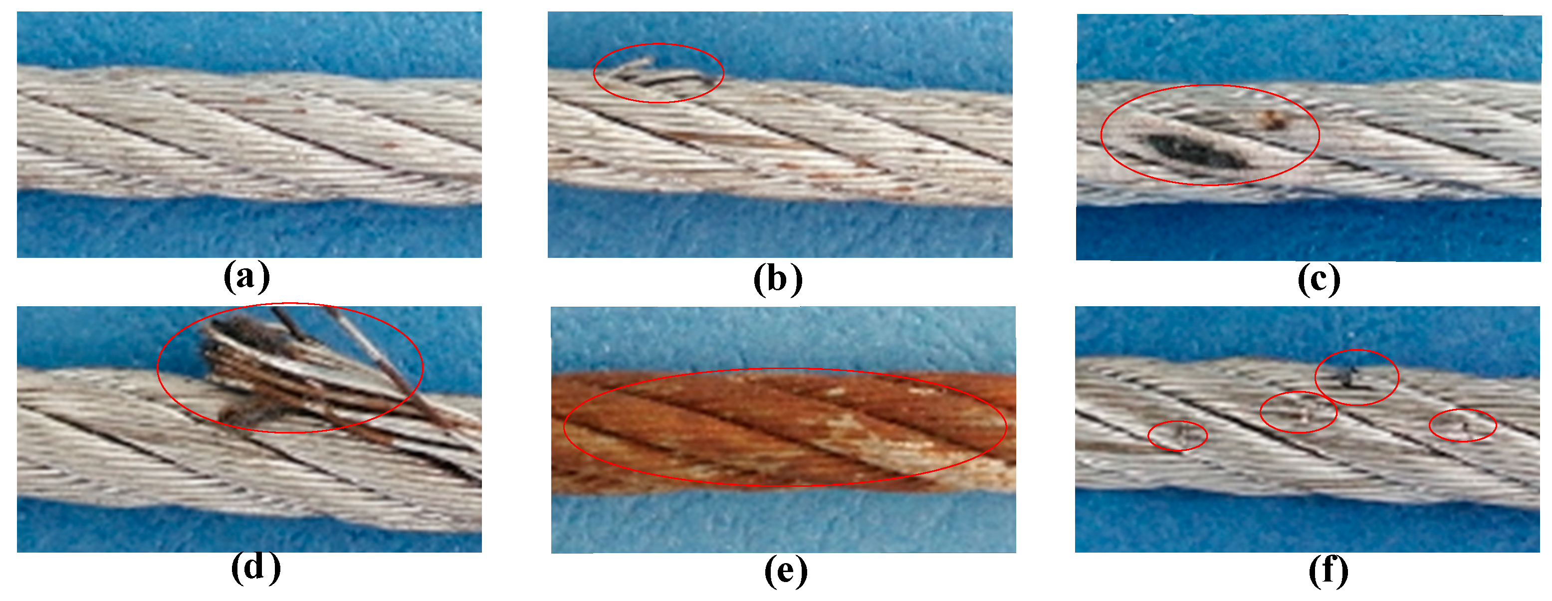
Examine slings for wear, fatigue, crushed or broken wires, kinking, ballooning or "bird-caging", heat damage, etc. Check both before and after using slings to detect any damage or defects. See Hoist wire rope for more inspection tips.

Wire ropes are essential for safety purposes on construction sites and industrial workplaces. They are used to secure and transport extremely heavy pieces of equipment – so they must be strong enough to withstand substantial loads. This is why the wire rope safety factor is crucial.
You may have heard that it is always recommended to use wire ropes or slings with a higher breaking strength than the actual load. For instance, say that you need to move 50,000 lbs. with an overhead crane. You should generally use equipment with a working load limit that is rated for weight at least five times higher – or 250,000 lbs. in this case.
This recommendation is all thanks to the wire rope safety factor. This calculation is designed to help you determine important numbers, such as the minimum breaking strength and the working load limit of a wire rope.
The safety factor is a measurement of how strong of a force a wire rope can withstand before it breaks. It is commonly stated as a ratio, such as 5:1. This means that the wire rope can hold five times their Safe Work Load (SWL) before it will break.
So, if a 5:1 wire rope’s SWL is 10,000 lbs., the safety factor is 50,000 lbs. However, you would never want to place a load near 50,000 lbs. for wire rope safety reasons.
The safety factor rating of a wire rope is the calculation of the Minimum Break Strength (MBS) or the Minimum Breaking Load (MBL) compared to the highest absolute maximum load limit. It is crucial to use a wire rope with a high ratio to account for factors that could influence the weight of the load.
The Safe Working Load (SWL) is a measurement that is required by law to be clearly marked on all lifting devices – including hoists, lifting machines, and tackles. However, this is not visibly listed on wire ropes, so it is important to understand what this term means and how to calculate it.
The safe working load will change depending on the diameter of the wire rope and its weight per foot. Of course, the smaller the wire rope is, the lower its SWL will be. The SWL also changes depending on the safety factor ratio.
The margin of safety for wire ropes accounts for any unexpected extra loads to ensure the utmost safety for everyone involved. Every year there aredue to overhead crane accidents. Many of these deaths occur when a heavy load is dropped because the weight load limit was not properly calculated and the wire rope broke or slipped.
The margin of safety is a hazard control calculation that essentially accounts for worst-case scenarios. For instance, what if a strong gust of wind were to blow while a crane was lifting a load? Or what if the brakes slipped and the load dropped several feet unexpectedly? This is certainly a wire rope safety factor that must be considered.
Themargin of safety(also referred to as the factor of safety) measures the ultimate load or stress divided by theallowablestress. This helps to account for the applied tensile forces and stress thatcouldbe applied to the rope, causing it to inch closer to the breaking strength limit.
A proof test must be conducted on a wire rope or any other piece of rigging equipment before it is used for the first time.that a sample of a wire rope must be tested to ensure that it can safely hold one-fifth of the breaking load limit. The proof test ensures that the wire rope is not defective and can withstand the minimum weight load limit.
First, the wire rope and other lifting accessories (such as hooks or slings) are set up as needed for the particular task. Then weight or force is slowly added until it reaches the maximum allowable working load limit.
Some wire rope distributors will conduct proof loading tests before you purchase them. Be sure to investigate the criteria of these tests before purchasing, as some testing factors may need to be changed depending on your requirements.
When purchasing wire ropes for overhead lifting or other heavy-duty applications, understanding the safety dynamics and limits is critical. These terms can get confusing, but all of thesefactors serve an important purpose.
Our company has served as a wire rope distributor and industrial hardware supplier for many years. We know all there is to know about safety factors. We will help you find the exact wire ropes that will meet your requirements, no matter what project you have in mind.
The use of rope for any purpose results in friction, bending and tension. All rope, hardware, sheaves rollers, capstans, cleats, as well as knots are, in varying degrees, damaging to ropes. It’s important to understand that rope is a moving, working, strength member and even under the most ideal conditions will lose strength due to use in any application. Maximizing the safety of rope performance is directly related to how strength loss is managed and making sure ropes are retired from service before a dangerous situation is created. Ropes are serious working tools and used properly will give consistent and reliable service. The cost of rope replacement is extremely small when compared to the physical damage or personnel injury that can result from using a worn out rope.
There are basically three steps to consider in providing the longest possible service life for ropes, the safest conditions and long range economy: Selection, Usage and Inspection.
Selecting a rope involves evaluating a combination of factors. Some of these factors are straight forward, like comparing rope specifications. Others are less qualitative, like color preference or how a rope feels while handling. Cutting corners, reducing design factors, sizes or strengths on an initial purchase creates unnecessary replacements, potentially dangerous conditions and increased long term costs. Fiber and construction being equal, a larger rope will outlast a smaller rope, because of greater surface wear distribution. By the same token, a stronger rope will outlast a weaker one, because it will be used at a lower percentage of its break strength and corresponding Work Load Limit with less chance of overstressing. The following factors should be considered in your rope selection: Strength, Elongation, Firmness, Construction and Abrasion.
When given a choice between ropes, select the strongest of any given size. A load of 200 pounds represents 2% of the strength of a rope with a 10,000 Lbs. breaking strength. The same load represents 4% of the strength of a rope that has a 5,000 Lbs. breaking strength. The weaker rope will work harder and as a result will have to be retired sooner. Braided ropes are stronger than twisted ropes that are the same size and fiber type.
Please note that the listed break strengths are average break strengths and do not consider conditions such as sustained loads or shock loading. Listed break strengths are attained under laboratory conditions. Remember also that break strength is not the same as the Work Load Limit.
It is well accepted that ropes with lower elongation under load will give you better control. However, ropes with lower elongation that are shock loaded, like a lowering line, can fail without warning even though the rope appears to be in good shape. Low elongating ropes should be selected with the highest possible strength. Both twisted ropes and braided ropes are suitable for rigging. Size for size, braided rope has higher strength and lower stretch than a twisted rope of similar fiber. See page 390 for additional information on rope elongation.
Select ropes that are firm and hold their shape during use. Soft or mushy ropes will snag easily and abrade quickly causing accelerated strength loss.
Rope construction plays an important role in resistance to normal wear and abrasion. Braided ropes have a basically round, smooth construction that tends to flatten out somewhat over the bearing surface. Flattening distributes wear over a much greater area, as opposed to the crowns of a three strand or to a lesser degree, an eight strand rope.
All rope will be severely damaged if subjected to rough surfaces or damaging edges. All rope must be protected against damaging or abrasive surfaces. Wire rope will score and gouge chocks and bitts creating cutting edges that can damage synthetic ropes. Chocks, bitts, drums and other surfaces must be kept in good condition and free of burrs and rust. Weld beads on repaired capstans, fairleads, etc., are equally damaging, unless dressed down smoothly. Pulleys must be free to rotate and should be of proper size to avoid
Avoid using a rope that shows signs of aging and wear. If in doubt, do not use the rope. Damaged rope must be destroyed to prevent any future use. No visual inspection can be guaranteed to accurately and precisely determine the residual strength of the rope. When fibers show wear in any area, the damaged area must be removed and the rope should be re-spliced or replaced. Check regularly for frayed or broken strands. Pulled strands should be rethreaded into the rope if possible. A pulled strand can snag on a foreign object during usage. Both outer and inner rope fibers may contribute to the strength of the rope. When either is worn the rope is naturally weakened. Open the strand of the rope and inspect for powdered fiber, which is one sign of internal wear. A heavily used rope will often become compacted or hard, which indicates reduced strength. The rope should be discarded and made unusable if this condition is detected. See pages 395 and 396 for additional inspection information.
New rope tensile strength is based upon tests of new and unused spliced rope of standard construction in accordance with Samson testing methods, which conform to Cordage Institute, ASTM and OCIMF test procedures. It can be expected that strengths will decrease as soon as a rope is put into use. Because of the wide range of rope use, changes in rope conditions, exposure to the many factors affecting rope behavior and the possibility of risk to life and property, it is impossible to cover all aspects of proper rope applications or to make generalized statements as to Work Load Limits.
Work Load Limits are the load that a rope in good condition with appropriate splices in non-critical applications is subjected to during normal activity. They are normally expressed as a percentage of new rope strength and should not exceed 20% of the stated break strength. Thus, your maximum Work Load Limit would be 1/5 or 20% of the stated break strength.
A point to remember is that a rope may be severely overloaded or shock loaded in use without breaking. Damage and strength loss may have occurred without any visible indication. The next time the rope is used under normal Work Loads and conditions, the acquired weakness can cause it to break.
Normal Work Load Limits do not cover dynamic conditions such as shock loads or sustained loads, nor do they apply where life, limb or property are involved. In these cases a stronger rope must be used and/or a higher design factor applied.
Normal Work Load Limits are not applicable when rope is subjected to dynamic loading. Whenever a load is picked up, stopped, moved or swung there is increased force due to dynamic loading. The more rapidly or suddenly such actions occur, the greater the increase in the dynamic loading. In extreme cases, the force put on the rope may be two, three or many more times the normal Work Load involved. Examples of dynamic loading would be: towing applications, picking up a load on a slack line or using a rope to stop a falling object. Dynamic loading affects low elongation ropes like polyester to a greater degree than higher elongation, nylon ropes. Dynamic loading is also magnified on shorter length ropes when compared to longer rope lengths. Therefore, in all such applications, normal Work Load Limits do not apply.
Work Load Limits as described do not apply when ropes have been subjected to shock loading. Whenever a load is picked up, stopped, moved or swung, there is an increased force due to dynamic loading. The more rapidly or suddenly such actions occur, the greater this increase in force will be. The load must be handled slowly and smoothly to minimize dynamic effects. In extreme cases, the force put on the rope may be two, three or even more times the normal Work Load involved. Examples of shock loading are picking up a tow on a slack line or using a rope to stop a falling object. Therefore, in all applications such as towing lines, life lines, safety lines, climbing ropes, etc., design factors must reflect the added risks involved. Users should be aware that dynamic effects are greater on a low elongation rope such as manila than on a high-elongation rope such as nylon and greater on a shorter rope than on a longer one.
The shock load that occurs on a winch line when a 5,000 Lbs. object is lifted vertically with a sudden jerk may translate the 5,000 Lbs. of weight into 30,000 Lbs. of dynamic force, which could cause the line to break. Where shock loads, sustained loads or where life, limb or valuable property is involved, it is recommended that a much higher design factor than 5 be used.
Remember, shock loads are simply a sudden change in tension, from a state of relaxation or low load to one of high load. The further an object falls, the greater the impact. Synthetic fibers have a memory and retain the effects of being overloaded or shock loaded. Ropes that have been shock loaded can fail at a later time, when used within Work Load Limits.
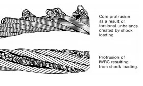
Shock loading can occur in any situation where the load on the crane suddenly increases. The crane and accessories are designed to take up the weight of loads gradually and steadily. They are not designed to withstand sudden increases or decreases in the apparent weight of the load. Some examples of how shock loading can occur are shown below.
Operators and equipment owners should be aware of the causes and potential dangers of shock loading. Because the equipment is being used in a way that it is not designed for, shock loading can lead to damaging the equipment, the facility, or injuring personnel. Understanding the causes of shock loading will help to prepare operators to safely and accurately operate the equipment.
Skilled operators are a company"s first defense against shock loading. Lifting and lowering should always be done in slow speed until all slack has been taken out of the wire rope and any below the hook devices. Additionally, operators should be aware of their surroundings, making sure that the load they are lifting is not likely to snag on other pieces of machinery or the building itself. When lifting or lowering the load, operators should be careful to make sure the load is not bouncing as they operate the hoist. Additionally, operators should ensure that their loads are secure and well balanced.
Beyond operator training and best practices, features such as the HoistMonitor®assist operators in preventing shock loads. The HoistMonitor ensures that starting and stopping is initiated in slow speed, which helps prevent a jumping motion of the load. Sudden load supervision, also a standard feature of the HoistMonitor, prevents the hoist from continuing the hoisting motion when a load increase is suddenly detected, like if the load snagged on another item.
The Working Load Limit is the maximum load which should ever be applied to the product, even when the product is new and when the load is uniformly applied – straight line pull only. Avoid side loading. All catalog ratings are based upon usual environmental conditions and consideration must be given to unusual conditions such as extreme high or low temperatures, chemical solutions or vapors, prolonged immersion in salt water, etc. Never exceed the Working Load Limit.
A load resulting from rapid change of movement, such as impacting, jerking or swinging of a static load. Sudden release of tension is another form of shock loading. Shock loads are generally significantly greater than static loads. Any shock loading must be considered when selecting the item for use in a system.
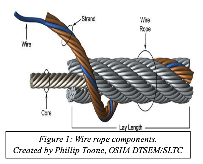
Wire rope and cable are each considered a “machine”. The configuration and method of manufacture combined with the proper selection of material when designed for a specific purpose enables a wire rope or cable to transmit forces, motion and energy in some predetermined manner and to some desired end.
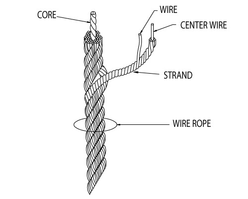
Two or more wires concentrically laid around a center wire is called a strand. It may consist of one or more layers. Typically, the number of wires in a strand is 7, 19 or 37. A group of strands laid around a core would be called a cable or wire rope. In terms of product designation, 7 strands with 19 wires in each strand would be a 7×19 cable: 7 strands with 7 wires in each strand would be a 7×7 cable.
Materials Different applications for wire rope present varying demands for strength, abrasion and corrosion resistance. In order to meet these requirements, wire rope is produced in a number of different materials.
Stainless Steel This is used where corrosion is a prime factor and the cost increase warrants its use. The 18% chromium, 8% nickel alloy known as type 302 is the most common grade accepted due to both corrosion resistance and high strength. Other types frequently used in wire rope are 304, 305, 316 and 321, each having its specific advantage over the other. Type 305 is used where non-magnetic properties are required, however, there is a slight loss of strength.
Galvanized Carbon Steel This is used where strength is a prime factor and corrosion resistance is not great enough to require the use of stainless steel. The lower cost is usually a consideration in the selection of galvanized carbon steel. Wires used in these wire ropes are individually coated with a layer of zinc which offers a good measure of protection from corrosive elements.
Cable Construction The greater the number of wires in a strand or cable of a given diameter, the more flexibility it has. A 1×7 or a 1×19 strand, having 7 and 19 wires respectively, is used principally as a fixed member, as a straight linkage, or where flexing is minimal.
Selecting Wire Rope When selecting a wire rope to give the best service, there are four requirements which should be given consideration. A proper choice is made by correctly estimating the relative importance of these requirements and selecting a rope which has the qualities best suited to withstand the effects of continued use. The rope should possess:Strength sufficient to take care of the maximum load that may be applied, with a proper safety factor.
Strength Wire rope in service is subjected to several kinds of stresses. The stresses most frequently encountered are direct tension, stress due to acceleration, stress due to sudden or shock loads, stress due to bending, and stress resulting from several forces acting at one time. For the most part, these stresses can be converted into terms of simple tension, and a rope of approximately the correct strength can be chosen. As the strength of a wire rope is determined by its, size, grade and construction, these three factors should be considered.
Safety Factors The safety factor is the ratio of the strength of the rope to the working load. A wire rope with a strength of 10,000 pounds and a total working load of 2,000 pounds would be operating with a safety factor of five.
It is not possible to set safety factors for the various types of wire rope using equipment, as this factor can vary with conditions on individual units of equipment.
The proper safety factor depends not only on the loads applied, but also on the speed of operation, shock load applied, the type of fittings used for securing the rope ends, the acceleration and deceleration, the length of rope, the number, size and location of sheaves and drums, the factors causing abrasion and corrosion and the facilities for inspection.
Fatigue Fatigue failure of the wires in a wire rope is the result of the propagation of small cracks under repeated applications of bending loads. It occurs when ropes operate over comparatively small sheaves or drums. The repeated bending of the individual wires, as the rope bends when passing over the sheaves or drums, and the straightening of the individual wires, as the rope leaves the sheaves or drums, causing fatigue. The effect of fatigue on wires is illustrated by bending a wire repeatedly back and forth until it breaks.
The best means of preventing early fatigue of wire ropes is to use sheaves and drums of adequate size. To increase the resistance to fatigue, a rope of more flexible construction should be used, as increased flexibility is secured through the use of smaller wires.
Abrasive Wear The ability of a wire rope to withstand abrasion is determined by the size, the carbon and manganese content, the heat treatment of the outer wires and the construction of the rope. The larger outer wires of the less flexible constructions are better able to withstand abrasion than the finer outer wires of the more flexible ropes. The higher carbon and manganese content and the heat treatment used in producing wire for the stronger ropes, make the higher grade ropes better able to withstand abrasive wear than the lower grade ropes.
Effects of Bending All wire ropes, except stationary ropes used as guys or supports, are subjected to bending around sheaves or drums. The service obtained from wire ropes is, to a large extent, dependent upon the proper choice and location of the sheaves and drums about which it operates.
A wire rope may be considered a machine in which the individual elements (wires and strands) slide upon each other when the rope is bent. Therefore, as a prerequisite to the satisfactory operation of wire rope over sheaves and drums, the rope must be properly lubricated.
Loss of strength due to bending is caused by the inability of the individual strands and wires to adjust themselves to their changed position when the rope is bent. Tests made by the National Institute of Standards and Technology show that the rope strength decreases in a marked degree as the sheave diameter grows smaller with respect to the diameter of the rope. The loss of strength due to bending wire ropes over the sheaves found in common use will not exceed 6% and will usually be about 4%.
The bending of a wire rope is accompanied by readjustment in the positions of the strands and wires and results in actual bending of the wires. Repetitive flexing of the wires develops bending loads which, even though well within the elastic limit of the wires, set up points of stress concentration.
The fatigue effect of bending appears in the form of small cracks in the wires at these over-stressed foci. These cracks propagate under repeated stress cycles, until the remaining sound metal is inadequate to withstand the bending load. This results in broken wires showing no apparent contraction of cross section.
Experience has established the fact that from the service view-point, a very definite relationship exists between the size of the individual outer wires of a wire rope and the size of the sheave or drum about which it operates. Sheaves and drums smaller than 200 times the diameter of the outer wires will cause permanent set in a heavily loaded rope. Good practice requires the use of sheaves and drums with diameters 800 times the diameter of the outer wires in the rope for heavily loaded fast-moving ropes.
It is impossible to give a definite minimum size of sheave or drum about which a wire rope will operate with satisfactory results, because of the other factors affecting the useful life of the rope. If the loads are light or the speed slow, smaller sheaves and drums can be used without causing early fatigue of the wires than if the loads are heavy or the speed is fast. Reverse bends, where a rope is bent in one direction and then in the opposite direction, cause excessive fatigue and should be avoided whenever possible. When a reverse bend is necessary larger sheaves are required than would be the case if the rope were bent in one direction only.
Stretch of Wire Rope The stretch of a wire rope under load is the result of two components: the structural stretch and the elastic stretch. Structural stretch of wire rope is caused by the lengthening of the rope lay, compression of the core and adjustment of the wires and strands to the load placed upon the wire rope. The elastic stretch is caused by elongation of the wires.
The structural stretch varies with the size of core, the lengths of lays and the construction of the rope. This stretch also varies with the loads imposed and the amount of bending to which the rope is subjected. For estimating this stretch the value of one-half percent, or .005 times the length of the rope under load, gives an approximate figure. If loads are light, one-quarter percent or .0025 times the rope length may be used. With heavy loads, this stretch may approach one percent, or .01 times the rope length.
The elastic stretch of a wire rope is directly proportional to the load and the length of rope under load, and inversely proportional to the metallic area and modulus of elasticity. This applies only to loads that do not exceed the elastic limit of a wire rope. The elastic limit of stainless steel wire rope is approximately 60% of its breaking strength and for galvanized ropes it is approximately 50%.
Preformed Wire Ropes Preformed ropes differ from the standard, or non-preformed ropes, in that the individual wires in the strands and the strands in the rope are preformed, or pre-shaped to their proper shape before they are assembled in the finished rope.
This, in turn, results in preformed wire ropes having the following characteristics:They can be cut without the seizings necessary to retain the rope structure of non-preformed ropes.
They are substantially free from liveliness and twisting tendencies. This makes installation and handling easier, and lessens the likelihood of damage to the rope from kinking or fouling. Preforming permits the more general use of Lang lay and wire core constructions.
Removal of internal stresses increase resistance to fatigue from bending. This results in increased service where ability to withstand bending is the important requirement. It also permits the use of ropes with larger outer wires, when increased wear resistance is desired.
Outer wires will wear thinner before breaking, and broken wire ends will not protrude from the rope to injure worker’s hands, to nick and distort adjacent wires, or to wear sheaves and drums. Because of the fact that broken wire ends do not porcupine, they are not as noticeable as they are in non-preformed ropes. This necessitates the use of greater care when inspecting worn preformed ropes, to determine their true condition.


 8613371530291