
single layer wire rope quotation

There are different ways of creating wire ropes, and each produces a rope that offers unique stress and rotational qualities suited to specific tasks. For most tasks, the two primary types of rope in use are stranded and spiral wire ropes.
Stranded wire ropes—steel strands wound in one or more layers around a core made of synthetic material, a wire strand, or a wire rope—secure loads as wire rope slings or running ropes because, in addition to being stressed by tensile forces, they take stress by being bent over the items that they are securing.
The three types of spiral wire rope, steel strands wound in opposing helical layers to make them nearly non-rotating, offer their own positives and negatives. Open spiral wire rope, made only from round wires, is suited to lighter applications. The half- and full-locked variants have a round wire core surrounded by profile strands that protect the rope and keep it lubricated. Given these qualities, spiral ropes are generally used as stationary ropes and stay ropes as they are good with both static and fluctuating tensile stresses. Full-locked ropes also serve as track ropes for cable cars, ski-lifts, cranes, and similar machines as they experience an increase in their free-bending radius when the tensile force increases, decreasing the bending stresses on the rope. As the roller force increases, however, that tensile force, along with the free-bending radius of the rope, decreases.
6 strands, nominally 19 wires per strand This class is the most widely used and is found in its many variations throughout many industries. With its good combination of flexibility and wear resistance, rope in this class is suited to the specific needs of many kinds of machinery and equipment. The designation 6x19 is only nominal; the number of wires ranges from 15 to 26. The following constructions are included in this class:
6x25 Filler Wire. In this construction, there are 19 main wires in each strand, plus six small filler wires. The filler wires are located between the outer layer of 12 wires and the inner layer of six. They provide support and stability to the strand. This construction is the best combination of flexibility and abrasion resistance found in the 6x19 Class.
6x19 Warrington. Each strand is made up of 19 wires. The outer layer of 12 wires has two different sizes of wire; the inner layer of six is one size of wire. The Warrington construction is somewhat less flexible than 6x25 Filler Wire, but more flexible than 6x21 Filler Wire.
6x21 Filler Wire. Each strand is made up of 21 wires. The rope has an outer layer of 10 large wires, an inner layer of five smaller wires and a still smaller center wire. There are five filler wires, located between the outer layer of ten wires and the inner layer of five. The 6x21 Filler Wire ropes are more wear-resistant but less flexible than Warrington, and less abrasion-resistant but more flexible than 6x19 Seale constructions.
6x26 Warrington Seale. This construction is composed of 26-wire strands. It has the same size outer wires as the 6x21 Filler Wire, with an inner wire configuration similar to the 6x36 Class ropes. Thus, it combines the wear resistance of a 6x19 rope with a flexibility between 6x19 and 6x36 Class ropes.
6x19 Seale. This construction has an outer layer of nine large wires, an inner layer of nine smaller wires and a single center wire. The Seale ropes are the least flexible of the 6x19 Class ropes. However, the large outer wires, solidly supported, provide resistance to abrasion and crushing.
The 6x36 Class of wire rope is characterized by the relatively large number of wires in each strand. Ropes of this class are more flexible than the 6x19 Class, but their resistance to abrasion is less than the 6x19 Class ropes.
The designation 6x36 is only nominal, as is the case with 6x19 Class. Ropes in the 6x36 Class may contain 27 to 49 wires per strand. Improvements in wire rope design, as well as changing machine designs, resulted in the use of strands with widely varying numbers of wires and geometry.
Larger wire ropes frequently incorporate a larger number of wires, resulting in a more complex geometry than found in the 6x19 or 6x36 Class wire ropes. WW’s 6x61 Class Bethlehem Mining Ropes generally are designed to comply with ASTM A 1023 geometry, although we added some innovations. WW strands the 6x61 Class Bethlehem Mining Ropes in a single operation, relying on dense, well fitted geometry to provide exceptional rope performance and the flexibility normally associated with 6x61 Class ropes.
The 6x61 Class ropes have a Seale-Filler Wire-Seale design, as shown in the cross sections below, containing from 50 to 77 wires per strand. WW further enhances Bethlehem Mining Rope performance by wire metallurgy and wire properties which are selectively modified to augment the specific rope geometries.
Many wire rope users have observed that heavily loaded ropes fail internally due to the failure of the IWRC. Such conditions illustrate that heavy IWRC stresses exist, which promote fewer fatigue cycles and create short rope life. WW designed Maxi-core to improve rope life under these conditions.
Maxi-core utilizes an IWRC design which features eight strands around a strand center. Maxi-core’s IWRC provides longer life, and, therefore, increases the overall service life of the rope. Because of its specialized IWRC, Maxi-core is resilient and able to accommodate shock loads better than conventional IWRC designs. Maxi-core also adds 33% more core support to the outer strands, thereby reducing internal stresses and promoting longer rope life. As with all Bethlehem Excavator Family Ropes, WW does not publish Maxi-core rope strengths. WW relies on specific rope improvements and specialized features to provide rope designs which give proven, superior field service.
This plastic jacket acts as a cushion or shock absorber between adjacent main strands and at main strand-to-IWRC contact points. The improved internal support is especially significant for ropes subjected to continual bending stresses and fluctuating loads (shock loading). Reduction of wear and damage at internal contact points results in longer and more predictable service life.
Compacted Strands: Beth Pac Beth Pac refers to rope manufactured by compacting each individual strand before closing the rope. In comparison to conventional wire rope, Beth Pac has a higher metallic area, improved crushing resistance and a smoother surface contacting sheaves and drums.
Beth Pac is offered in Excavator and Excavator-AR in diameters 21/4" through 23/4" in 8x36 construction for hoist ropes. Beth Pac can be combined with other Bethlehem Mining Rope features, such as En-core. For more information and help in determining your need for Beth Pac and other available sizes, please contact WW’s Sales and Engineering Departments.
BXL is furnished as right regular or lang lay, Form-set, IWRC wire rope manufactured in the 6x19, 6x36 and 8x36 Classes. Available grades are Excavator and Excavator-AR. For specific information, please refer to the table. For information on smaller diameters for mining applications, please contact our Customer Service Department.
BXL provides the characteristics common to Bethlehem Mining Rope, enhanced by the plastic-infusion. BXL starts with WW’s special wire grades used in the manufacture of mining rope. Excavator grade is designed to provide excellent resistance to bending fatigue, such as those conditions found with hoist ropes. Excavator-AR is intended for those applications where more abrasive operating conditions exist, such as in drag line applications. Enhanced by plastic infusion, BXL offers several improved features.
Improved fatigue resistance is one key feature of BXL. BXL’s polymer cushions each wire and strand, minimizing interstrand and interlayer nicking. BXL also offers improved abrasion resistance. The polymer acts as a barrier between the individual strands, preventing penetration of any adverse material, such as dust, dirt and metal particles. The polymer also distributes and reduces contact stresses between the rope and sheave, reducing the wire rope wear normally associated with uncoated wire rope. Perhaps the most important feature of BXL, however, is the polymer’s ability to maintain the balance of the rope. When a rope is in operation, or simply wound upon a drum, the rope’s components move and adjust accordingly.
Due to the nature of wire rope, this movement may cause accelerated wear, and in uncoated rope, may also produce a flattening or ovaling of the rope. The polymer in BXL minimizes this movement by locking the individual wires and strands in place. With the rope’s holding its intended shape during operation, operating stresses such as vibration are evenly distributed to all wires and strands, thereby reducing fatigue breaks and increasing service life.
This rope is particularly suitable where severe crushing and abrasion on a drum occur, or where a higher strength design is required than can be obtained with a similar round strand rope. The triangular strand shape not only provides better resistance to crushing, but also offers a greater exposed surface area for contact with sheaves, drums or underlying areas of spooled rope.
This feature, combined with Lang lay, distributes the abrasive wear over a greater number and longer length of wires. The broad, smooth surface of the rope also helps to minimize wear on drums and sheaves.
We make a full line of tail ropes customized to meet your requirements of strength and weight to balance your friction hoist system. Please contact your salesman or customer service with your specifications and we will supply a quotation to meet your needs.
Wire rope is shipped in cut lengths, either in coils or on reels. Great care should be taken when the rope is removed from the shipping package since it can be permanently damaged by improper unreeling or uncoiling. Looping the rope over the head of the reel or pulling the rope off a coil while it is lying on the ground, will create loops in the line. Pulling on a loop will, at the very least, produce an imbalance in the rope and may result in open or closed kinks (Fig. 18). Once a rope is kinked, the damage is not repairable. The kink must be cut out or the rope is unfit for service.
Figure 18.Improper handling can create open (a) or, closed kinks b). The open kink will open the rope lay: the closed kink will close it. Starting loop (c): Do not allow the rope to form a loop. If. however, a loop does form and is removed at the stage show. a kink can be avoided. Kink (d): In this case. the looped rope was put under tension, the kink was formed. the rope is permanently damaged.
There are three methods to perform this step correctly:The reel is mounted on a shaft supported by two jacks or a roller payoff (Fig.19). Since the reel is free to rotate, the rope is pulled from the reel by a workman holding the rope end, and walking away from the reel as it unwinds. A braking device should be employed so that the rope is kept taut and the reel is restrained from over-running the rope. This is necessary particularly with powered de-reeling equipment.
Another method involves mounting the reel on an unreeling stand (Fig. 20). It is then unwound in the same manner as described above (1). In this case, however, greater care must be exercised to keep the rope under tension sufficient to prevent the accumulation of slack. Slack can allow the rope to drop below the lower reel head and be damaged or loose wraps on the reel to fall
In another accepted method, the end of the rope is held while the reel itself is rolled along the ground. With this procedure, the rope will payoff properly however, the end being held will travel in the direction the reel is being rolled. As the difference between the diameter of the reel head and the diameter of the wound rope increases, the speed of travel will increase.
Figure 19. The wire rope reel is mounted on a shaft supported by jacks. This permits the reel to rotate freely. and the rope can be unwound either manually or by a powered mechanism.
When re-reeling wire rope from a horizontally supported reel to a drum it is preferable for the rope to travel from the top of the reel to the top of the drum; or, from the bottom of the reel to the bottom of the drum (Fig. 21). Re-reeling in this manner will avoid putting a reverse bend into the rope during installation. If a rope is installed so that a reverse bend is induced, it may cause the rope to become "twisty" and, consequently, harder to handle. When unwinding wire rope from a coil, there are two suggested methods for carrying out this procedure in a proper manner:
1) One method involves placing the coil on a vertical unreeling stand. The stand consists of a base with a fixed vertical shaft. On this shaft there is a "swift," consisting of a plate with inclined pins positioned so that the coil may be placed over them. The whole swift and coil then rotate as the rope is pulled off. This method is particularly effective when the rope is to be wound on a drum.
2) The most common as well as the easiest uncoiling method is merely to hold one end of the rope while rolling the coil along the ground like a hoop (Fig. 22). Figures 23 and 24 show unreeling and uncoiling methods that are most likely to cause kinks. Such improper procedures must be avoided in order to prevent the occurrence of loops. These loops, when pulled taut, will inevitably result in kinks. No matter how a kink develops, it will damage strands and wires, and the kinked section must be cut out. Proper and careful handling will keep the wire rope free from kinks.
Drums are the means y which power is transmitted to the rope and then to the object to be moved. For the wire rope to pick up this power efficiently and to transmit it properly to the working end, the installation must be carefully controlled. If the drum is grooved, the winding conditions should be closely supervised to assure adherence to the following recommended procedures:
I) The end of the rope must be secured to the drum by such means as will give the end termination at least as much strength as is specified by the equipment manufacturer.
2) Adequate tension must be maintained on the rope while it is being wound so that the winding proceeds under continuous tension. Back tension applied to the rope during installation" should be from 2 to 5% of the minimum breaking force of the rope being installed.
4) It is preferable to have at least three dead wraps remaining on the drum when the rope is unwound during normal operation. Two dead wraps are a mandatory requirement in many codes and standards. If the wire rope is carelessly wound and, as a result, jumps the grooves, it will be crushed and cut where it crosses from one groove to the other. Another, almost unavoidable problem is created at the drum flange; as the rope climbs to a second layer there is further crushing and the wires receive excessive abrasion.
drum grooves relative to the actual rope diameter. Wire rope is normally manufactured to a plus tolerance. (See Table 3.) The oversize tolerance of the rope must be taken into account or the rope will be damaged by poor spooling caused
inches. Yet, by Federal standards, a 1/4-inch rope may have a diameter as large as .265 inches. If a rope of this size were to be operated on a drum with a .250 inch pitch, crowding would occur and the rope would be forced out of the groove.
Installation of a wire rope on a plain (smooth) face drum requires a great deal of care. The starting position should be at the correct drum flange so that each wrap of the rope will wind tightly against the preceding wrap (Fig. 32). Here too, close supervision should be maintained during installation. This will help make certain that:
2 ) Appropriate tension on the rope is maintained as it is wound on the drum. Back tension applied to the rope during installation should be from 2 to 5% of the minimum breaking force of the rope being installed.
4) It is preferable to have at least three dead wraps remaining on the drum when the rope is unwound during normal operation. Two dead wraps are a mandatory requirement in many codes and standards. Loose and uneven winding on a plain (smooth) faced drum can and usually does create excessive wear, crushing and distortion of the rope. The results of such abuse are shorter service life and a reduction in the rope"s effective strength. Also, for an operation that is sensitive in terms of moving and spotting a load, the operator will encounter control difficulties as the rope will pile up, pull into the pile and fall from the pile to the drum surface. The ensuing shock can break or otherwise damage the rope.
Figure 32. By holding the right or left hand with index finger extended, palm up or palm down, the proper procedure for applying left-and right-lay rope on a smooth drum can be easily determined.
The proper direction of winding the first layer on a smooth drum can be determined by standing behind the drum and looking along the path the rope travels, and then following one of the procedures illustrated in Figure 32. The diagrams show: the correct relationship that should be maintained between the direction of lay of the rope (right or left), the direction of rotation of the drum (overwind or underwind) and winding from left to right or right to left. Order Wire Rope & Cable
Many installations are designed with requirements for winding more than one layer of wire rope on a drum. Winding multiple layers presents some further problems.The first layer should wind in a smooth, tight helix which, if the drum is grooved,
is already established. The grooves allow the operator to work off the face of the drum, and permit the minimum number of dead wraps. A smooth drum present" an additional problem, initially, as the wire rope must be wound in such a manner that the first layer will be smooth and uniform and will provide a firm foundation for the layers of rope that will be wound over it. The first layer of rope on the smooth drum should be wound with tension (2 to 5% of the minimum breaking force of the rope) sufficient to assure a close helix - each wrap being wound as close as possible to the preceding wrap. The first layer then acts as a groove which will guide the successive layers. Unlike wire ropes operating on grooved drums, the first layer should not be unwound from a smooth-faced drum with multiple layers. After the rope has wound completely across the face of the drum (either smooth or grooved), it is forced up to a second layer at the flange. The rope then winds back across the drum in the opposite direction, lying in the valleys between the wraps of the rope on the first layer. Advancing across the drum on the second layer, the rope, following the "grooves" formed by the rope on the first layer, actually winds back one wrap in each revolution of the drum. The rope must then cross one or two rope "grooves" (depending upon the type of grooving - single or double cross-over) in order to advance across the drum for each turn. The point at which this occurs is known as the cross-over. Cross-over is unavoidable on the second, and all succeeding layers. Figure 33 illustrates the winding of a rope on the second layer from left to right, and from right to left-the direction is shown by the arrows.
At these cross-over points, the rope is subjected to severe abrasion and crushing as it is pushed over the "grooves" and rides across the crown of the first rope layer. The scrubbing of the rope, as this is happening, can easily be heard.
Helical grooving does not employ a built in cross-over and does not work as well for multiple layers spooling as a counterbalanced drum because it does not have the cross-over and does not consistently put the rope in the proper position at the
Counterbalance grooving with two cross-overs is made so that each wrap of rope winds parallel to the drum flange for a distance less than half the circumference around the drum, then follows a short cross-over to complete half the drum circumference. The cross-over is at an angle with the drum flange and displaces the rope laterally by half the pitch of grooving.
The grooving for this type of winding is similar to the parallel grooving except that half the drum circumference is laterally displaced from the other half by half the pitch of grooving, and between these two halves the grooves make short cross-overs to guide the rope properly. The two cross-over areas are on opposite sides of the drum, or 1800 apart.
Since the lateral displacement of each cross-over is one half the pitch of grooving, or one half the displacement of the cross-overs encountered with other types of winding, "throw" of the rope is reduced, decreasing the whipping action. However, if the interval between these displacements happens to match the rope"s vibration cycle, whipping can still become severe because this action is cumulative.
Since the cross-over areas are spaced opposite each other, or 1800 apart, raised portions of the winding caused by vertical displacement at the cross-overs also occur opposite each other. These raised sections become quite pronounced where many layers are involved and the balancing effect of keeping them opposite gave name to the method.
With counterbalance winding, the change of layers can be controlled better than with other systems and is preferred when a rope must wind in many layers on the drum.
Rotation resistant wire rope refers to a series of steel ropes which minimizes the tendency to spin or rotation under load. These wire ropes boast special design - the outer layer is twisted in the reverse direction of inner layers for counteracting torsional forces generated from multi-layers of strands.
To achieve the resistance against the spin and rotation, all wire ropes are composed of at least two layers of strands. In general, more layers a rotation resistant wire rope has, more resistance it will boast. For example, 2-layer ropes is much easier to spin and rotate than 3-layer ones. Meanwhile, if one end of free rotation is allowed, 2-layer rope can only develop 55% to 75% of its breaking strength comparing with 95% to 100% of 3-layer ropes.
The 3-layer rope with more outer strands is capable to distribute more radial pressure onto inner layers and ideal for larger mobile such as all tower cranes.
Wire ropes with 8 to 10 strands & 2-layer constructions without reversely twisted inner strands have very similar appearance to rotation resistant wire ropes, but they are not.
Rotation resistant wire ropes are considered to be less stable needing to be handled and installed with great care. They must be taken to avoid high loads with small diameter sheaves.
Compacted wire rope, also known as swaged wire rope, has a greater steel area which results in higher crush resistance and significantly enhanced drum spooling. A smooth outer strand profile improves rope wear resistance and reduces sheave and drum wear while the greater contact area between each strand reduces inter-strand nicking and increases flexibility under load, enhancing fatigue life and overall performance.
DyPac 6 compacted single layer rope delivers high performance and reduces equipment maintenance as the DyPac compaction process increases the steel area of the individual strands, producing a rope with greater strength and increased lifting capability. We offer DYTY-6 compacted wire rope (6x26) in addition to compacted bright wire rope (35x7 and 19x19).
High strength standard 6-strand rope for applications which require a crush resistant rope to be used on multiple layer winding systems; e.g. boom hoist on lattice boom mobile- and tower cranes. This rope has also shown remarkable performance gains as main hoist rope on port container cranes and on some overhead crane applications.
Python® Construct-6 is a swaged rope which is constructed from specialty made engineered and sized 6-strand wire rope. The basic wire rope is already manufactured with purpose intend to be swage compacted into the finished product. The degree of swage compacting is carefully selected to ensure the best compromise between crush- and fatigue resistance. The strength increase compared to standard 6-strand ropes varies between about plus 10% to 35% depending on rope diameter.
Python® Construct-6 is available as a 25-wire (6 F-V) or 36-wire (6WS-V) construction, in leftand right lay, bright or galvanized. Choose 6 F-V as Boom Hoist rope, 6 WS-V for single layer drum hoisting.
Note: The maximum CAPACITY, WORKING LOAD LIMIT (WLL), or LINE PULL of the rope usually is 1/5 of the below stated values. For specific information consult the standards applicable to your rope application.
6-strand rope with flat outer wire surface resisting drum crushing and aiding in better multiple layer spooling. Compacting removes most of constructional stretch.
The more wires there are in a strand of wire rope of a given diameter, the more flexible that rope will be. One of the key aspects of the usefulness of rope, wire or otherwise, is its ability to bend and wrap around pulleys and sheaves. If a rope cannot bend, it will not be as useful.
When a rope does bend, the wires and strands that make up the rope slide on top of each other. Because of this, wire ropes that will experience significant bending will need to be lubricated. In addition, the actual wires experience bending stress which can, over time, lead to fatigue failure. If the stresses are higher than the yield point of the wires, the wire rope may experience a permanent deformation.
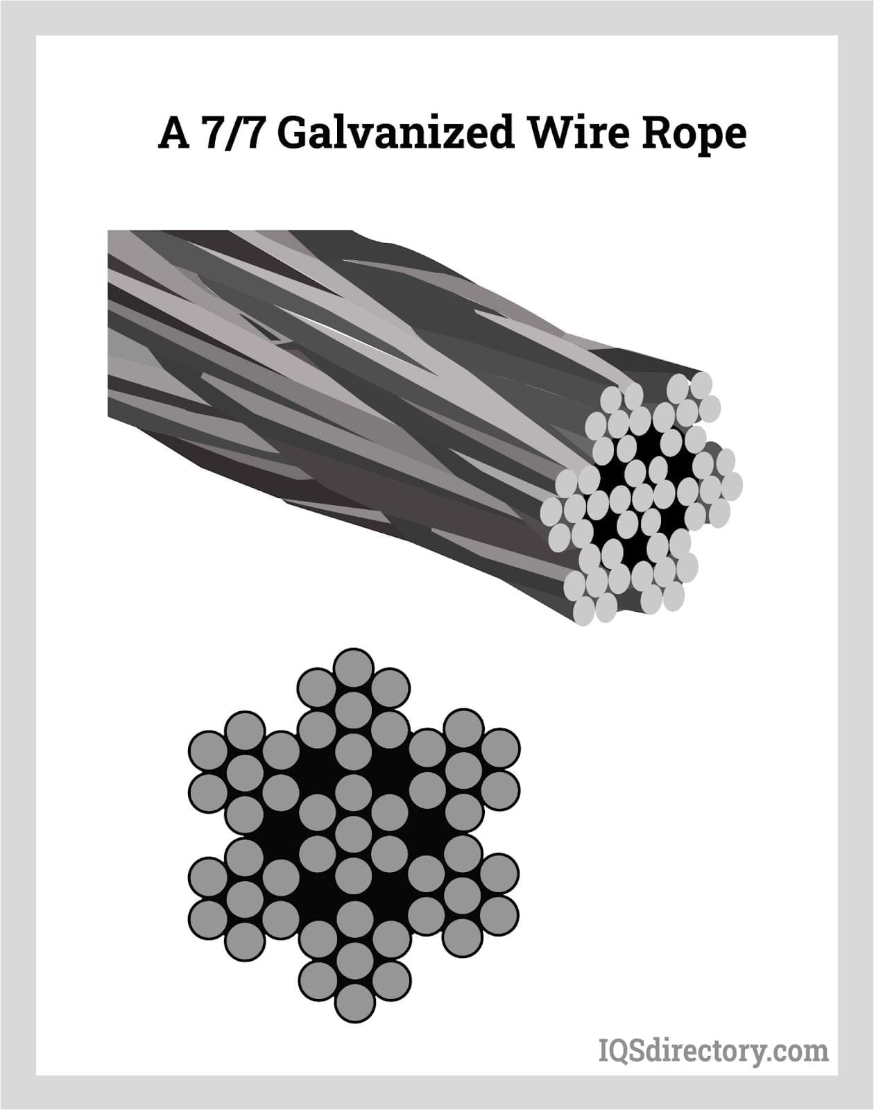
Each strand in a wire rope is comprised of multiple wires (usually 7, 19, or 37). A rope with 7 strands of 19 wires would be referred to as a 7×19 wire rope. This type of designation serves as the class of the wire. These numbers may be followed by a pair of letters that provide information about how the outside layer of the wire rope is constructed.
The lay of a rope refers to how the wire strands are twisted. A regular lay wire rope has the wires twisted one way and the strands twisted in the opposite direction. A lang lay, on the other hand, has the wires and strands wrapped in the same direction. A regular lay is going to be less likely to kink or untwist compared to a lang lay, but a lang lay is going to have better abrasion resistance and flexibility. Lay can also be designated as right or left: a right lay wraps around the core in a clockwise direction, while a left lay wraps around in a counter-clockwise direction.
The finish of a wire rope refers to the coating (if any) applied to the strands. If a rope is described as bright finish, it is made from high carbon steel wires that have no finish or protective coating applied to them. A galvanized finish has a coating of zinc added to enhance corrosion protection. Another finish option is a zinc aluminum coating added to wire for 3x better corrosion protection than a galvanized finish.
The more wires there are in a strand of wire rope of a given diameter, the more flexible that rope will be. One of the key aspects of the usefulness of rope, wire or otherwise, is its ability to bend and wrap around pulleys and sheaves. If a rope cannot bend, it will not be as useful.
When a rope does bend, the wires and strands that make up the rope slide on top of each other. Because of this, wire ropes that will experience significant bending will need to be lubricated. In addition, the actual wires experience bending stress which can, over time, lead to fatigue failure. If the stresses are higher than the yield point of the wires, the wire rope may experience a permanent deformation.
There are several key wire rope characteristics that must be considered when choosing the right one for your application. One of the most important characteristics of wire rope is its strength which is typically reported as its minimum breaking force (MBF). However–and this is very important–a wire rope should never be used at its MBF.
A stranded rope should also have an application-appropriate crushing resistance. The crushing resistance refers to the rope’s ability to resist having its cross-section, stands, wires, or core deformed by outside forces. This is similar to the ability of a rope to resist deformation in the form of wire rope peening, where the outside wires of the rope appear to have been hammered.
Fatigue resistance is another key aspect of choosing the right wire rope and particularly applies to ropes that experience bending stresses. The longer a wire rope is exposed to bending stresses, the less strength it is going to have. A rope with a higher fatigue resistance is going to have a longer useful life. The more wires in a rope, the better its fatigue resistance. However, the size of the wire rope also plays a key part: ropes should not be bent over drums or sheaves that force the rope to bend sharply.
When a load is placed on a rope, the wires will try to straighten out to accommodate a load, generating a torque that can cause the rope to spin. Some need to be rotation resistant wire rope to prevent the load from rotating when applied to the rope. A similar characteristic is the stability of the rope, which refers to the ability of the rope to spool smoothly or avoid tangling.
Another key wire rope characteristic is its resistance to metal loss, which usually affects the outside wires of the rope and occurs through abrasion. As the rope rubs against other hard surfaces, metal can be worn away from the outer wires.
Overhead crane wire ropes are used in many different industries, including mining, oil & gas, marine, steel, logging, ski lifts, and elevators. It is vitally important that you find the right wire rope for your application, whether you need a rotation-resistant wire rope for a critical petrochemical application or a general-purpose wire rope for a winch. If you are in the market for stranded core wire rope, contact the experts at Hi-Speed Industrial Service.

Wire rope is a collection of metal strands that have been twisted and wound to form the shape of a helix with the purpose of supporting and lifting heavy loads and performing tasks that are too rigorous for standard wire. On shipping docks, rigging, and load bearing equipment, wire rope is attached to swivels, shackles, or hooks to lift a load in a controlled, even, and efficient manner.
The uses for wire rope include adding support to suspension bridges, lifting elevators, and serving as additional reinforcement for towers. The design of wire rope, with its multiple strands wrapped around a stable core, provides strength, flexibility, and ease of handling for applications that have bending stress.
Individual designs of wire rope involve different materials, wire, and strand configurations as a means for supporting and assisting in the completion of lifting or supportive applications.
The term wire rope encompasses a wide range of mechanical tools that are made to perform heavy and extreme lifting jobs. Wire rope is a complicated and complex tool with multiple moving parts capable of moving in unison. A 6 by 25 wire rope has 150 outer strands that move as one in an intricate pattern supported by a flexible core.
An essential part of the design of wire rope is the required clearance between the strands to give each stand the freedom to move and adjust when the rope bends. It is this unique feature that differentiates wire rope from solid wire and other forms of cable.
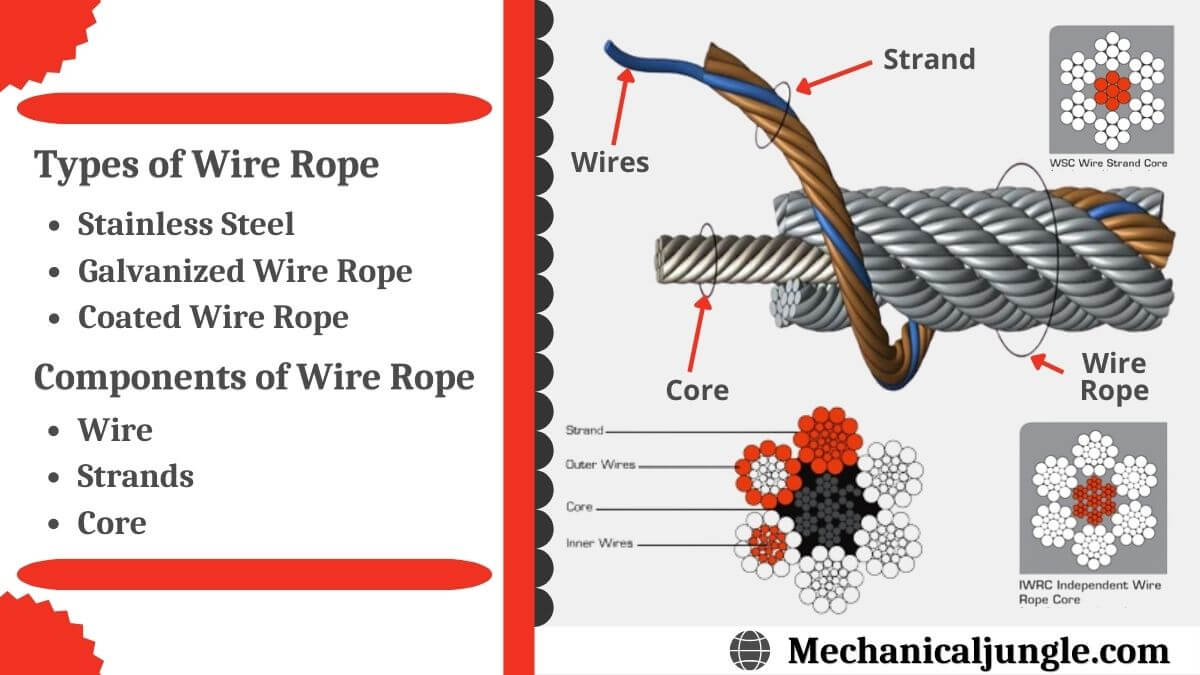
The basic element of wire rope is wire that is used to configure, shape, and form the rope. Typically, steel, stainless steel, and galvanized wires are the first choice with aluminum, nickel alloy, bronze, copper, and titanium being second possibilities. The choice of wire is dependent on the type of work the wire is going to be used to perform with strength, flexibility, and abrasion resistance being the major determining factors.
Stainless steel wire rope has all of the basic qualities of galvanized and general wire rope with the added benefits of corrosion and rust resistance; this makes it the ideal choice for harsh and stressful conditions.
Steel wire rope is classified as general purpose wire rope and comes in a wide variety of sizes, diameters, and strengths. It is the most common type of wire rope and is used for several industrial, manufacturing, and construction applications.
Before going further into the discussion of how wire rope is made, it is important to understand the numbers used to describe each type. All wire ropes have a core around which wires are wound. The various styles of cores vary according to the construction and design of the requirements of the wire rope that is being produced.
Wire rope is classified by the number of strands it has as well as the number of wires in each strand. The most common classification is a seven wire rope that has one strand in the center and six around its circumference. This type of wire rope is lightweight with a very simple construction. The majority of wire ropes are more complex and intricate with multiple intertwining strands and wires.
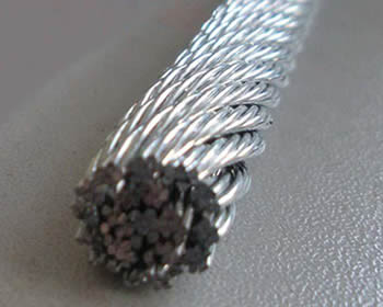
What must be understood about wire rope is that it has a complicated configuration. It is actually wires wrapped around wires to form bundles that are wrapped around other bundles. In the case of a seven wire wire rope, the core has bundles of wires wound around it; this can be seen in the image below.
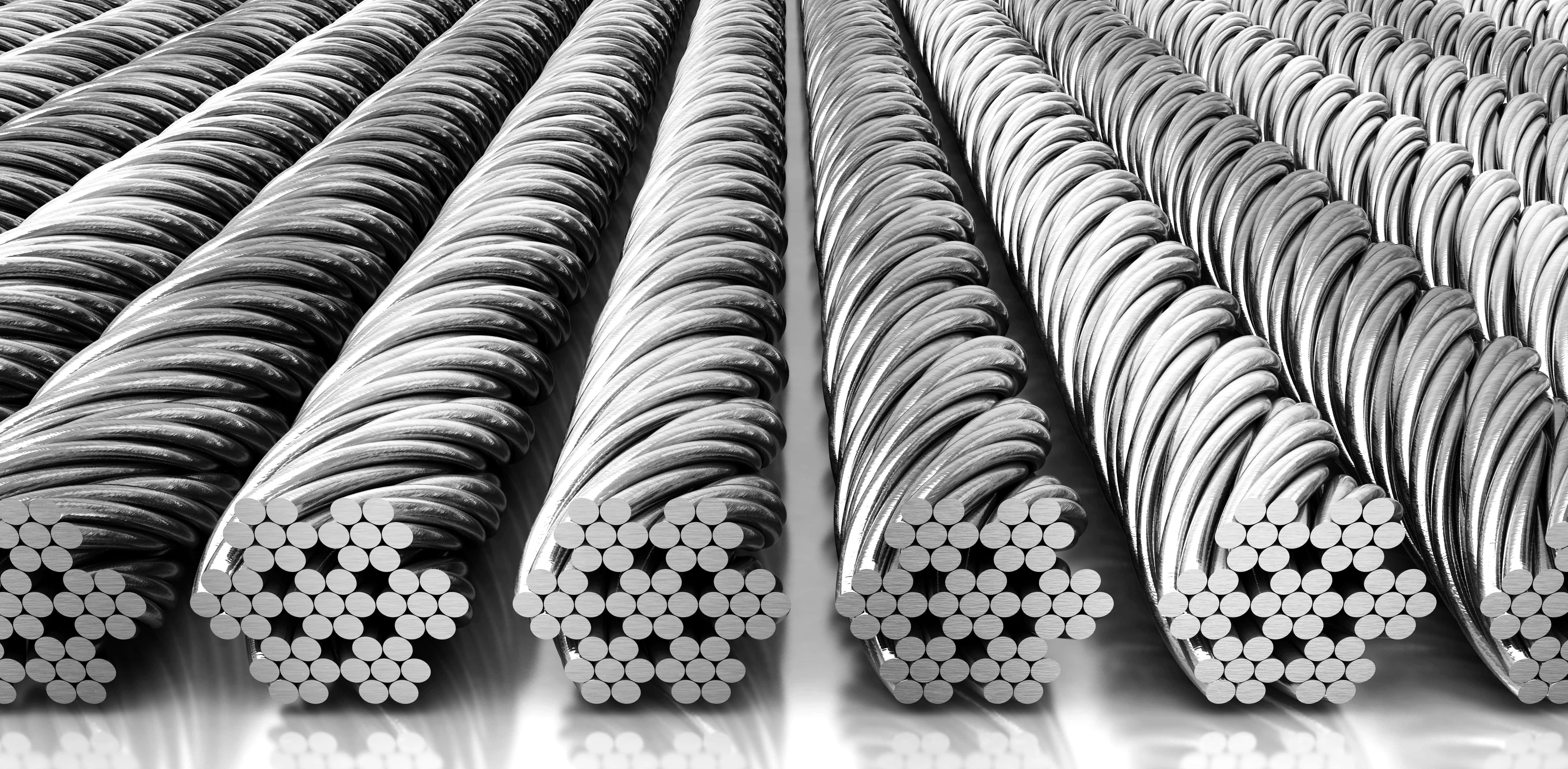
The first step in wire rope creation is the production of wire strands where wires are wound around a single core wire. The number of wires included in the strand is dependent on the specified strength, flexibility, and size requirements of the rope. Once the strand is completed, it is straightened before being moved to wire rope construction.
Like wire ropes, strands have different patterns; patterns are the arrangements of the wires and their diameters. Though most strands have a core, there are strand patterns that have three or four wires without a core that are referred to as centerless strands. The design of each strand pattern is meant to enhance the strength of the wire rope and improve its performance.
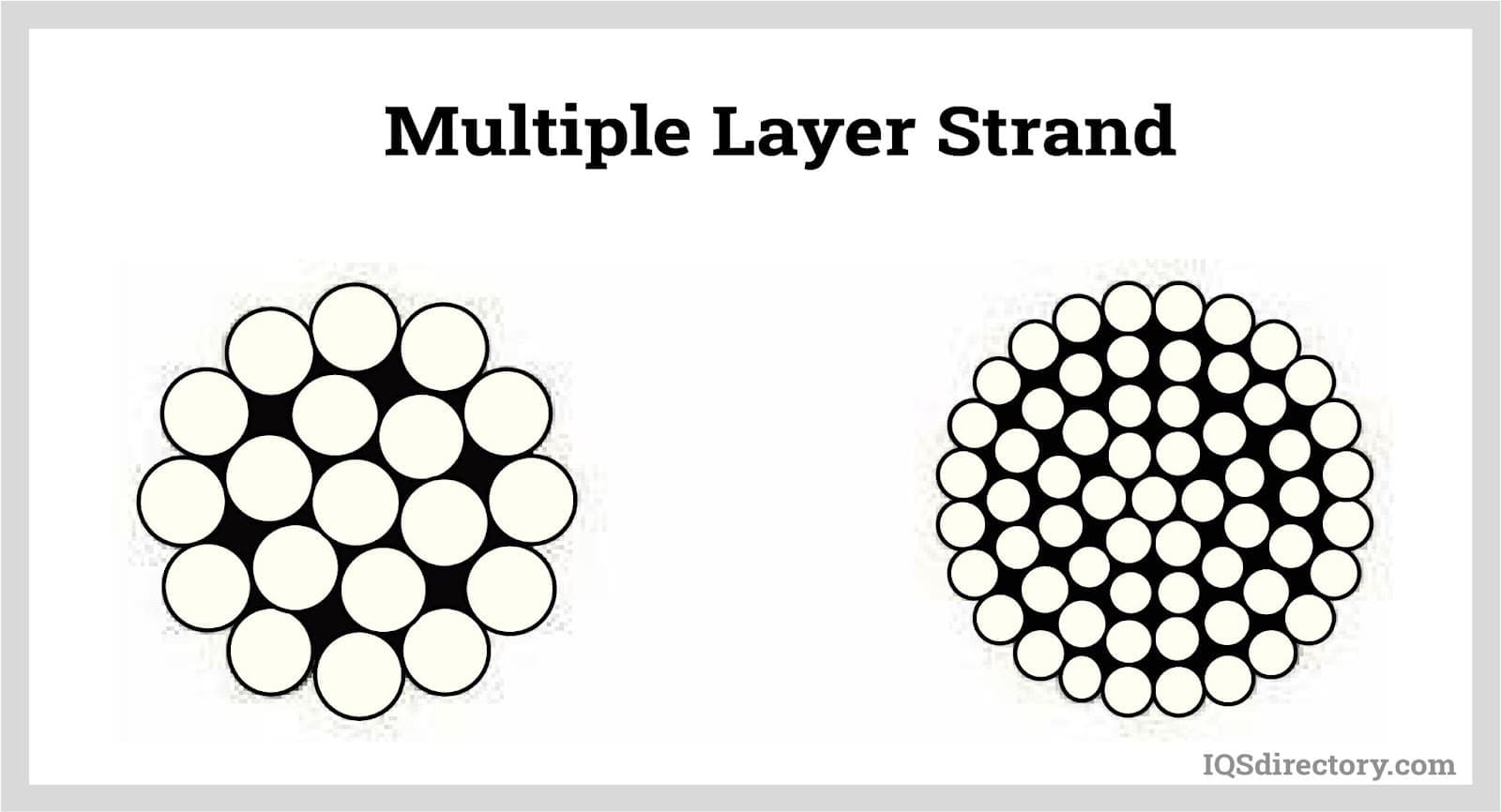
For a multiple layer strand, the layers of wire are placed over one another in successive order. The placement of the wires on top of each other must be such that they fit smoothly and evenly.
The Warrington pattern is like the multiple layer pattern with one variation. Like the multiple layer pattern, the inner wires and the core are the same and have the same diameter. The difference is in the outer layer, which has wires of alternating sizes of large and small with larger diameter wires laying in the valleys of the inner wires.
All of the wires of a filler pattern are the same size. What makes this pattern unique is the insertion of small wires in the valleys of the inner wires to fill the gap between the inner and outer layer.
The flattened strand pattern is also known as the triangular strand, which can be triangular or oval. Three round wires form the core. The outer flattened surface has a greater sectional metallic area; this makes this pattern stronger and longer lasting.
The core of a wire rope runs through the center of the rope and can be composed of a variety of materials, which include synthetic fibers, natural fibers, a single strand, or another wire rope. The core supports the wound strands, helps maintain their position, is an effective lubricant carrier, and provides support.
Wire ropes with fiber cores are restricted to light loads and are not used in severe, harsh, or stressful conditions. Polypropylene and nylon are types of synthetic fiber cores and can be used in conditions where there is exposure to chemicals.
Cores made of wire are classified as independent wire cores. The core of a wire rope with a wire core is actually a wire rope with another wire rope serving as the core, as can be seen in the diagram below. These types of wire ropes are used where the rope will be exposed to exceptional resistance and crushing.
A strand, or wire strand core, is exactly like the rest of the strands of the wire rope with wires of the same diameter and size as the other strands.
The choice of core and creation of the strands are the simplest yet most essential parts of wire rope construction. Wire rope lays, the method used to wind the strands, is more complex and involves several choices.
Lay is a term used to describe three of the main characteristics of wire rope: direction, relationship, and linear distance. The strands can be wrapped around the core going right or left. Right or left refers to the direction of the strands wrapped around the core and the wires within the strands. The linear distance is how far a strand moves when it is making a revolution around the core.
In a regular lay, the wires and strands spiral in opposite directions. With a right hand regular lay, the wires spiral to the left and the strands to the right. In the left hand regular lay, the wires spiral to the right and the strands to the left. This type of lay is easy to handle but wears out quickly because the crown wires are in contact with the bearing surface.
In the Lang, or Albert, lay, the wires and strands spiral in the same direction with right hand lay being the most common. The wires in a Lang lay appear to run parallel to the center line of the rope. The difficulty with Lang lay wire ropes is handling since they tend to kink, twist, and crush.
Wire rope is an exceptionally strong tool that has been configured and designed to withstand the stress placed upon it through rigorous and continual use. In most applications, wire rope has to endure extreme stress and strain. It is for these reasons that coatings have been developed to protect wire rope from abrasions, corrosion, UV rays, and harmful and damaging chemicals.
Three main types of coatings are used to protect wire rope: polyvinyl chloride (PVC), polypropylene, and nylon. Of the three types, PVC is the most popular.
In cases where there are severe and hazardous working conditions, polypropylene is the recommended choice since it is capable of protecting wire rope against corrosion and chemical leaching. Additionally, it is resistant to impact damage and abrasion. Polypropylene is a tough, rigid, and crystalline thermoplastic that is made from a propene monomer and is resilient as well as inexpensive.
Braided wires are electrical conductors made up of small wires that are braided together to form a round tubular braid. The braiding and configuration of braided wire makes them very sturdy such that they do not break when flexed or bent. Braided wires are widely used as conductors, are commonly made from copper due to copper"s exceptional conductivity, and can be bare or coated depending on the application.
Braided wire can be round and tubular or flat. Round tubular braids fit in most spaces where flat braided wire will not. Flat braided wire begins as round braided wire which is flattened on a capstan. They are exceptionally strong and designed for medical and aircraft applications.
Metals used to make wire rope are various grades of stainless steel, bright steel, and galvanized steel. Though the majority of wire rope manufacturers use these three metals, other metals such as copper, aluminum, bronze, and monel are also used on a limited basis.
The most important aspect of wire rope is the wire and the metal from which it is made. The strength and resilience of wire rope is highly dependent on the quality of metal used to make it, and these are essential factors to be considered when purchasing it.
Bright steel wire does not have a coating and is rotation resistant, (designed to not rotate when lifting a load). It is drawn from hot rolled rods that are put through a die to match its specific dimensional tolerances, mechanical properties, and finish. Bright wire is used as a single line in conditions that require a rope that will resist cabling.
Galvanized steel has a zinc coating for corrosion resistance and has the same strength and durability as bright steel. Environmental conditions determine the use of galvanized steel. In mildly severe and slightly harsh conditions, galvanized steel wire is an economical replacement for stainless steel.
In the manufacturing process, galvanized wire goes through the process of galvanization, a method of coating steel wire with a protective and rust resistant metal. Galvanized wire is exceptionally strong, rust resistant, and flexible enough to meet the needs of a variety of applications.
Wire rope made from copper is mostly used for electrical applications due to its exceptional electrical characteristics. The benefits of copper wire rope are its durability, flexibility, and resilience compared to standard copper wire. The strength of copper wire rope is seen in its use in applications where there are vibrations and shaking.
The wire rope lubrication process begins during its fabrication and continues during its use. Lubrication of wire rope is designed to lower the amount of friction it endures and provide corrosion protection. Continued lubrication increases the lifespan of wire rope by preventing it from drying up, rusting, and breaking.
The types of lubricants for wire rope are penetrating or coating with coatings covering and sealing the outside of the rope. Penetrating lubricants go deep into the rope and seep into the core where they evaporate to form a thick coating or film.
The application of the lubricant is dependent on the type of core. Fiber cores absorb the lubricant and serve as a reservoir that retains the lubricant for an extended period of time. With metal cores, the lubricant is applied as the wire is twisted into strands to give complete saturation and coverage of the wires.
There are several types of greases that are used as wire rope lubricating agents and are made up of oil, a thickener, and additives. The essential components are the base oil and additives, which influence the behavior of the grease. The thickener holds the base oil and additives together. The amount of base oil in a grease is between 70% and 95% with an additive of 10%.
The additive in grease enhances the positive properties of the oil and suppresses the negative properties. Common additives are oxidation and rust inhibitors as well as pressure, wear, and friction reducing agents.
Of the many choices for lubricants, vegetable oil is the easiest to use and penetrates the deepest. The design of the additives for vegetable oils gives them the necessary qualities required to penetrate deep into a wire rope. The exceptional penetration provides protection against wear and corrosion. Since vegetable oil is a fluid, it helps in washing the wire rope to remove external abrasive contaminants.
Wire rope is widely used in machines, structures, and varied lifting applications. Its type, size, and requirements are determined by how it will be used. Regardless of its use, wire rope guarantees exceptional strength and provides high quality and excellent performance.
The lifting of heavy loads for centuries involved the use of hemp rope or chains, neither of which was a guaranteed or substantial method. Early in the 18th Century, between 1824 and 1838, Wilhelm Albert, a German mining engineer, combined the twisting of hemp and strength of chains to create today‘s wire rope.
The most common use of wire rope is as a part of a crane hoist wherein it is attached to the hook of the hoist and wrapped around a grooved drum. The tensile strength and durability of wire rope makes an ideal tool for lifting and keeping loads secure. Though it is used in several industries, it is very popular for production environments wherein materials need to be lifted quickly and efficiently.
In addition to its many lifting applications, the strength and stability of wire rope is useful in other applications, especially in the aerospace industry. Pedals, levers, and connectors in the cockpit of an aircraft are connected with wire rope. The wires provide for the passage of power between systems and mechanisms; this allows control of the aircraft. Wire rope is used to control propeller pitch, cowl flaps, and the throttle. It also assists in lowering and minimizing vibrations.
Tires are reinforced with wire rope to increase their durability and strength. All automotive production environments make use of wire ropes for supplying materials, moving heaving loads, and positioning equipment. Wire rope can be found in the production of steering wheels, cables, exhausts, springs, sunroofs, doors, and seating components.
As surprising as it may seem, the place that wire rope has the greatest use is in the home, where its strength, long life, endurance, and resilience provide guaranteed protection and performance. The main reason wire ropes are so popular for home use is cost.
Inexpensive, easy to obtain, easy to install, and easy to maintain, wire ropes provide an additional method for performing home repairs and structural support. Their excellent flexibility and sturdiness combined with their invisibility has made wire rope an ideal solution to several home maintenance issues. It is used to support staircases, fences, decks, and hang plants.
The search and production of crude oil has relied on wire ropes for centuries to lift drill bits, insert shafts, and support oil rigs on land and the water. When equipment, machinery, and tools have to be lowered into the depths of the earth and sea, wire ropes are the tool that the oil industry relies on to do the job.
Many of the tasks of oil production require tools that are capable of enduring severe and harsh conditions. Wire ropes have to withstand enormous pressure, extraordinary stress, and a wide range of temperatures. The use of wire rope includes maintaining oil rig stability and moorings for offshore rigs.
Wire rope has long been a standard component for the transportation industry, from the cable cars of San Francisco to the lift chairs for ski resorts. For many years, cable cars have relied on heavy duty cables (wire ropes) to be pulled by a central motor from multiple locations. It is a method of transportation that has existed for centuries.
In Europe, funiculars use cables that hang from a support to move cars up and down a mountain with cables moving in opposite directions. The word funicular is from the French word funiculaire, meaning railway by cable. The terms wire rope and cable are used interchangeably when discussed by professionals. The first part of funicular, or funiculaire, is from the Latin word "funis," meaning rope.
The major use for wire ropes in the food and beverage industries is as a means for lifting and moving heavy loads. Wine barrels and containers full of ingredients are lifted and placed through use of cranes and wire ropes. They are also part of conveyor systems that move products from one station to another.
From the beginnings of amusement rides up to the present, wire ropes have been an essential part of attraction construction and safety. They pull cars on roller coasters, hold cabins that swing, and move carriages through haunted houses. The main concern of amusement parks is safety. The strength, stability, and guaranteed performance of wire ropes ensures that people who attend amusement parks will have a good time and stay safe.
The rigging used to complete the stunts in modern movies depends on wire rope for safety. Much like in amusement rides, wire ropes protect performers from injury and harm as they hang above a scene or carry out an impossible move.
The live theater industry uses wire ropes to raise and lower curtains, support overhead rigging, and hold backdrops and scenery pieces. During a production, rapid and efficient movement is a necessity that is facilitated by the use of wire ropes.
Wire rope is a tool that we tend to envision as indestructible, unable to succumb to any form of damage. Though it is exceptionally sturdy and strong as well as capable of enduring constant use, it is just as susceptible to breakdown as any other tool.
To avoid serious harm and damage, wire ropes should be scheduled for regular inspections. There are situations that can damage or break a wire rope; these should be understood prior to the problem arising.
Guide rollers have the potential to damage and cause abrasions on wire rope if they become rough and uneven. Of the various elements of a crane and lift, guide rollers have the greatest contact with the mechanism‘s wire rope. Regular inspection of guide rollers will ensure they are not damaging the rope or causing abrasions.
Bending is normally a regular part of wire rope usage; this occurs repetitively as the rope passes through a sheave. As a wire rope traverses the sheave, it is continually bent and develops cracks or breaks. The cracking and breaking are exacerbated by movement on and off the groove of the drum. Normally, the breakage happens on the surface and is visible. Once it appears, it accelerates to the core of the rope.
A bird cage is caused by a sudden release of tension and a rebound of the rope. This type of break requires that the rope be replaced since the place of the break will not return to its normal condition.
Wire ropes are multi-layered; this makes them flexible and torque balanced. The layering inside and outside creates flexibility and wear resistance. Relative motion between the wires causes wear over time, which leads to internal breakage. The detection of these breaks can be indicated by an electromagnetic inspection that calculates the diameter of the rope.
Kinked wire rope is caused by pulling a loop on a slack line during installation or operation; this causes a distortion in the strands and wires. This is a serious condition that necessitates rope replacement.
Corrosion damage is the most difficult cause of wire rope damage to identify, which makes it the most dangerous. The main reason for corrosion is poor lubrication that can be seen in the pitted surface of the rope.
The types of damage and problems listed here are only a small portion of the problems that can be caused if a wire rope is not regularly lubricated and inspected. Various regulatory agencies require that wire ropes be inspected weekly or monthly and provide a list of factors to examine.
As with any type of heavy duty equipment, wire rope is required to adhere to a set of regulations or standards that monitor and control its use for safety and quality reasons. The two organizations that provide guidelines for wire rope use are the American Society of Mechanical Engineers (ASME) and the Occupational Safety and Health Administration (OSHA).
All wire rope manufacturers and users closely follow the standards and guidelines established by OSHA and ASME. In the majority of cases, they will identify the specific standards they are following in regard to their products.
OSHA‘s regulations regarding wire rope fall under sections 1910, 1915, and 1926, with the majority of the stipulations listed in 1926 under material handling, storage, use, and disposal.
"Running rope in service shall be visually inspected daily, unless a qualified person determines it should be performed more frequently. The visual inspection shall consist of observation of all rope that can reasonably be expected to be in use during the day‘s operations. The inspector should focus on discovering gross damage that may be an immediate hazard."
"The inspection frequency shall be based on such factors as rope life on the particular installation or similar installations, severity of environment, percentage of capacity lifts, frequency rates of operation, and exposure to shock loads. Inspections need not be at equal calendar intervals and should be more frequent as the rope approaches the end of its useful life. Close visual inspection of the entire rope length shall be made to evaluate inspection and removal criteria."
ASTM A1023 covers the requirements for steel wire ropes with specifications for various grades and constructions from ¼ in. (6 mm) to 31/2 in. (89 mm) manufactured from uncoated or metallic coated wire. Included are cord products from 1/32 in. (0.8 mm) to 3/8 in. (10 mm) made from metallic coated wire.
United States Federal Spec RR W 410 covers wire ropes and wire seizing strands but does not include all types, classes, constructions, and sizes of wire rope and strands that are available. The purpose of Spec RR W 410 is to cover more common types, classes, constructions, and sizes suitable for federal government use.
Wire rope and wire seizing strand covered by United States Federal Spec RR W 410 are intended for use in general hauling, hoisting, lifting, transporting, well drilling, in passenger and freight elevators, and for marine mooring, towing, trawling, and similar work, none of which are for use with aircraft.
API 9A lists the minimum standards required for use of wire rope for the petroleum and natural gas industries. The types of applications include tubing lines, rod hanger lines, sand lines, cable-tool drilling and clean out lines, cable tool casing lines, rotary drilling lines, winch lines, horse head pumping unit lines, torpedo lines, mast-raising lines, guideline tensioner lines, riser tensioner lines, and mooring and anchor lines. Well serving wire ropes such as lifting slings and well measuring are also included in API 9A.
Wire rope is a collection of metal strands that have been twisted and wound to form the shape of a helix with the purpose of supporting and lifting heavy loads and performing tasks that are too rigorous for standard wire.
Individual designs of wire rope involve different materials, wire, and strand configurations as a means for supporting and assisting in the completion of a lifting or supportive task.
19x7 wire rope is recommended for hoisting unguided loads with a single-part line. The rotation-resistant properties of this rope are superior to those of the 8x19 class wire ropes, and are secured by two layers of strands. The inner strands are left lay, while the 12 outer strands are right lay, which enables one layer to counteract the other layer’s rotation.
Galvanized wire rope (steel) features a compressed zinc coating for providing excellent corrosion resistance. With a higher break strength, yet lower price than stainless steel wire rope, galvanized steel wire rope is widely used in general engineering applications such as winches and security ropes.
The bright class of industrial wire rope is produced without a surface treatment—making the rope less likely to untwist or kink while giving it a stronger crush resistance than lay ropes. Generally, they are fully lubricated to protect the rope from rust and corrosion. Also available in USA-made.
They may look simple, but wire rope slings play a critical role in various industries, including construction, shipping, material handling, and rigging.
The unique physical properties and resistance to abrasion make it easier to use these slings with shackles, hooks, and swivels for a variety ofmaterial handling applications. They also provide strength, durability, and resistance to abrasion or elements.
However, this seemingly simple lifting device comes with a unique structure and functional properties. Let’s take a look at the complete anatomy of wire rope slings.
A typical wire rope sling consists of a wire rope made from small individual steel wires twisted together. Both ends of the wire rope are looped together individually to form a sling. The wire rope is the fundamental component of a sling.
A typical heavy-duty wire rope has multiple small twisted strands made from various grades of steel. The configuration and number of these strands changes, depending on how complicated the pattern is.
Usually, a typical rope comes with hundreds of outer wire strands covering the core strand. All these strands move together as well as independently, providing the wire rope with the necessary strength and flexibility. The mechanics of this movement are quite complex.
A wire is the smallest part of a wire rope. You can use different types of metals, including stainless steel, iron, steel, and bronze to make the wires. The grade of the material used for making the wire depends on strength, abrasion resistance, and durability required for the intended application.
You can create a strand by twisting two or more wires together tightly in a precise pattern. Again, the weaving pattern will be determined by the end-application of the rope.
It is made from steel or natural and sometimes synthetic fibers. The strands go around the core, which offers support when the rope bends or is attached to the load.
As mentioned, strand patterns are critical as they determine the strength, durability, and abrasion resistance of the rope. Usually, the strand consists of the number of wires per layer, the number of layers of wires, and the size (diameter) of the wires in each layer.
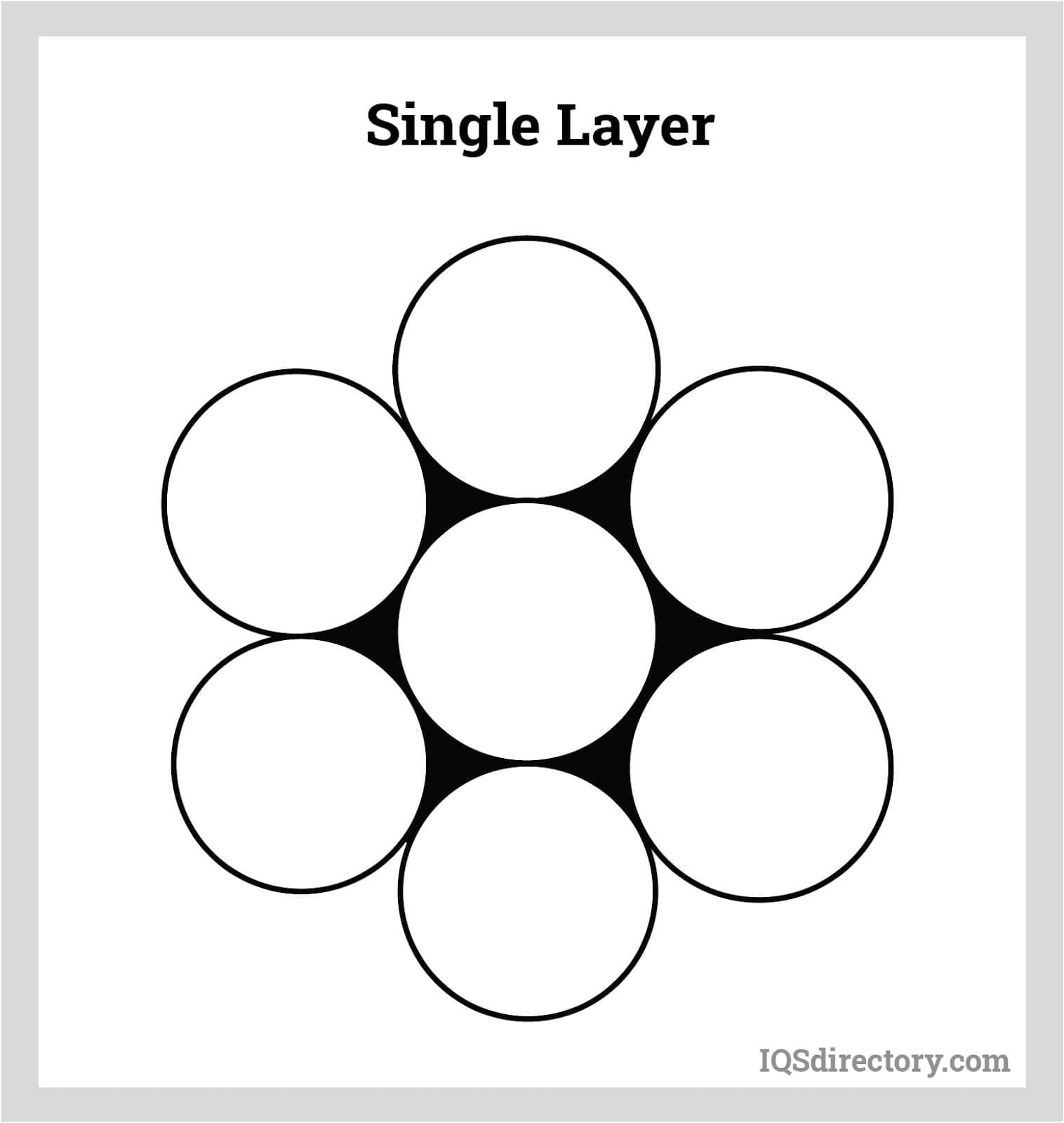
As the name suggests, this type of pattern consists of only one layer of wires around the core, all having the same size or diameter. There are usually six strands covering a core, totaling the number to seven.
It comprises two layers of wires wrapped around the core. The inner layer usually has six wires, while the outer layer has twelve with equal diameter. Six filler wires with a smaller diameter are used to fill the gap between the two layers of strands.
Like the filler pattern, this one also has two layers of wires surrounding the core. However, wires in the inner layer have a smaller diameter compared to the ones in the outer layer. The outer wires rest in the troughs of inner smaller wires.
This pattern also consists of two layers of wires. However, only the inner layer has wires with a uniform diameter. The ones in the outer layer have two sets of wires, one with a bigger diameter and the other with a smaller one.
In the outer layer, the bigger wires rest in the troughs of the inner layer, while the smaller ones rest on the crests on the wires in the inner layer.
This is one of the most common types of layering patterns. In this, the strand layering and the wire layering are in opposite directions. This arrangement provides the wire rope slings with exceptional resistance to crushing forces and offers better spooling.
In this type of structure, the wire layering and the core layering are in the same direction. However, the wires form an angle with the rope axis. This arrangement provides a higher resistance to fatigue and abrasion.
In this type of structure, manufacturers use both regular and lag layering in a suitable combination. However, alternate layering is designed for specialized applications only.
This is the most popular wire rope sling. In this type of loop, the spliced end of the rope is tied around the body of wire rope slings using a metal sleeve. The Flemish eye splice is best suited for six-strand ropes.
However, if you are using these loops with other types of wire ropes, you need to use aluminum or loop-back (turn-back) steel sleeves. The regular sleeves often cause an electrochemical reaction, which speeds up the deterioration process.
In this loop, an aluminum sleeve is pressed using fabrication over both rope parts. The integrity of the pressed sleeve solely determines the strength of these wire rope slings. You can also add thimbles to these slings.
This is similar to aluminum sleeve loop-back splice. However, it uses steel sleeves with a slightly smaller diameter. It can also be used for making stainless steel rope slings of a larger rope diameter.
The rope gets inserted into the fitting bore, and it then gets swagged onto the rope. With this method, you can attach open and closed sockets, buttons, threaded studs, and load hooks directly to the rope. The process results in a high-efficiency bond.
This is a type of socket that is attached to one or both ends of a wire rope to form a sling. The strength of these sockets is the actual rope strength.
As you can see, wire rope slings are a complex piece of lifting device, although they look simple. Hopefully, understanding their structure will help you know how they can offer the required strength, flexibility, and resistance to abrasion, crushing, and fatigue. It will also help you choose the right sling suitable for your application. Do tell us why and how you use these slings in your industry in the comments section.

Any assembly of wires spun into a helical formation (either as a strand or a wire rope), when subjected to a tensile load, can extend in three seperate phases, depending on the magnitude of the applied load:
Phase 1 and 2 are highly important because they represent a part of the qualities of the rope. Phase 3, on the other hand, can be caused by wrong choose of rope or lack of rope inspection. The phases are connected to eachother and cause a course of event in all ropes that are exposed to gradual increased load. Due to this a new rope, which are exposed to overloading, will go through phase 1 and 2 before the third phase (permanent extension) begin.
When loading a new product, extension is created by the bedding down of the assembled wires with a corresponding reduction in overall diameter. This reduction in diameter creates an excess length of wire which is accommodated by a lengthening of the helical lay.
When sufficientely large bearing areas have been generated on adjacent wires, to withstand the circumferential compressive loads, this mechanically created extension ceases and the extension in phase 2 commences.
The initial extention can not be accurately determined and depend on, apart from the strand or the rope construction, the various load and the current load frequency.
The proportionality factor normally is a material constant called Modulus of Elasticity (E-module). To steel wire ropes the E-module is more of a construction constant than a material constant.
The modulus of elasticity varies with different rope constructions. According to manufacturing factors, wire dimensions and a lot of other factors the E-module various between different wire ropes of the same construction and dimension. If exact E-module olf a certain rope is necassary a modulus test have to be done at that rope.
The elastic extension is valid until the proportionality or elasticity limit is reached. By loa


 8613371530291