
splicing steel wire rope made in china
Beijing Tianma Sling Co., Ltd has been in heavy lifting industry for more than 18 years. We are specialized in manufacturing all sizes of webbing slings, round sling, lashing straps, towing straps, polyester webbing, wire rope press machine, hydraulic testing machines, wire rope sling and other rigging equipment to the world market.
Our mainly produce webbing sling ,round sling ,wire rope press machine ,tensile testing machine,lifting spreader and other kinds of lifting slings and equipments.

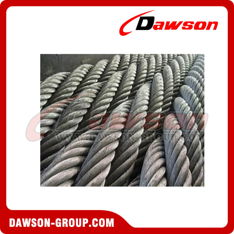
Wire rope is made of plaiting strands of wire – normally medium carbon steel –into a thick cable. The strands are formed around a core. The strands in wire ropes are made of wore twisted together. Strands with smaller diameter wires are less abrasion resistant and more fatigue resistant. Strands made with thicker length of wore are more abrasion resistant and less fatigue resistant.
Left-hand ordinary lay (LHOL) wire rope (close-up). Right-hand lay strands are laid into a left-hand lay rope. Right-hand Lang"s lay (RHLL) wire rope (close-up). Right-hand lay strands are laid into a right-hand lay rope.
Left hand lay or right hand lay describe the manner in which the strands are laid to form the rope. To determine the lay of strands in the rope, a viewer looks at the rope as it points away from them. If the strands appear to turn in a clockwise direction, or like a right-hand thread, as the strands progress away from the viewer, the rope has a right hand lay. The picture of steel wire rope on this page shows a rope with right hand lay. If the strands appear to turn in an anti-clockwise direction, or like a left-hand thread, as the strands progress away from the viewer, the rope has a left hand lay.
Ordinary and Lang"s lay describe the manner in which the wires are laid to form a strand of the wire rope. To determine which has been used first identify if left or right hand lay has been used to make the rope. Then identify if a right or left hand lay has been used to twist the wires in each strand. Ordinary lay The lay of wires in each strand is in the opposite direction to the lay of the strands that form the wire.
Alternate lay The lay of wires in the strands alternate around the rope between being in the opposite and same direction to the lay of the strands that form the wire rope.
The specification of a wire rope type – including the number of wires per strand, the number of strands, and the lay of the rope – is documented using a commonly accepted coding system, consisting of a number of abbreviations.
This is easily demonstrated with a simple example. The rope shown in the figure "Wire rope construction" is designated thus: 6x19 FC RH OL FSWR 6 Number of strands that make up the rope
Each of the sections of the wire rope designation described above is variable. There are therefore a large number of combinations of wire rope that can be specified in this manner. The following abbreviations are commonly used to specify a wire rope. Abbr. Description
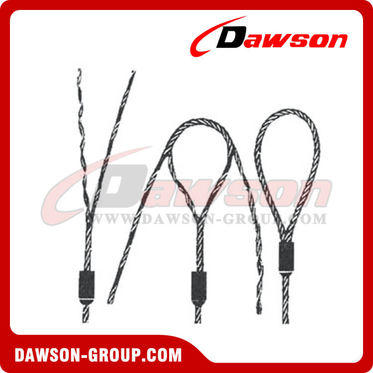
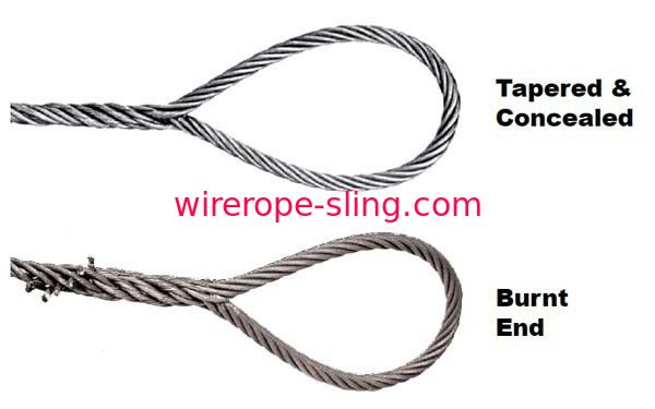
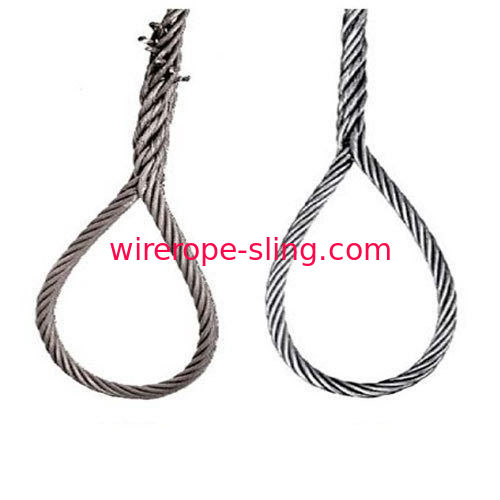
The end of a wire rope tends to fray readily, and cannot be easily connected to plant and equipment. A number of different mechanisms exist to secure the ends of wire ropes to make them more useful. The most common and useful type of end fitting for a wire rope is when the end is turned back to form a loop. The loose end is then fixed by any number of methods back to the wire rope.
When the wire rope is terminated with a loop, there is a risk that the wire rope can bend too tightly, especially when the loop is connected to a device that spreads the load over a relatively small area. A thimble can be installed inside the loop to preserve the natural shape of the loop, and protect the cable from pinching and abrasion on the inside of the loop. The use of thimbles in loops is industry best practice. The thimble prevents the load from coming into direct contact with the wires.
A wire rope clamp, also called a clip, is used to fix the loose end of the loop back to the wire rope. It usually consists of a u-shaped bolt, a forged saddle and two nuts. The two layers of wire rope are placed in the u-bolt. The saddle is then fitted over the ropes on to the bolt (the saddle includes two holes to fit to the u-bolt). The nuts secure the arrangement in place. Three or more clamps are usually used to terminate a wire rope.
Swaging is a method of wire rope termination that refers to the installation technique. The purpose of swaging wire rope fittings is to connect two wire rope ends together, or to otherwise terminate one end of wire rope to something else. A mechanical or hydraulic swager is used to compress and deform the fitting, creating a permanent connection. There are many types of swaged fittings. Threaded Studs, Ferrules, Sockets, and Sleeves a few examples.
A socket termination is useful when the fitting needs to be replaced frequently. For example, if the end of a wire rope is in a high-wear region, the rope may be periodically trimmed, requiring the termination hardware to be removed and reapplied. An example of this is on the ends of the drag ropes on a dragline. The end loop of the wire rope enters a tapered opening in the socket, wrapped around a separate component called the wedge. The arrangement is knocked in place, and load gradually eased onto the rope. As the load increases on the wire rope, the wedge become more secure, gripping the rope tighter.
Eye Splice The ends of individual strands of this eye splice used aboard a cargo ship are seized with natural fiber cord after the splicing is complete. This helps protect seaman"s hands when handling.
Referring to fig. 1-3, a splicing steel wire rope comprises a steel wire rope body 1 and a splicing mechanism arranged on the steel wire rope body 1; the splicing mechanism comprises a first splicing assembly and a second splicing assembly; the first splicing assembly and the second splicing assembly are respectively arranged at two ends of the steel wire rope body 1; the first splicing assembly and the second splicing assembly are matched at one end far away from the steel wire rope body 1; the second splicing assembly comprises a splicing head 6 and a connecting component 7, and the splicing head 6 is installed at one end of the steel wire rope body 1; the connecting part 7 is arranged on the splicing head 6; the connecting component 7 comprises a connecting rod 71, a movable sleeve 72, a limiting rod 73 and a spring 74, wherein the connecting rod 71 is arranged inside the splicing head 6; and both ends of the connecting rod 71 are provided with movable sleeves 72; the non-adjacent ends of the two movable sleeves 72 are respectively provided with a limiting rod 73, and the non-adjacent ends of the two limiting rods 73 are respectively extended to the outer surface of the splicing head 6; the spring 74 is sleeved on the connecting rod 71, and two ends of the spring 74 are respectively connected with one adjacent side of the two movable sleeves 72.
Wherein, four spouts 2 have been seted up to the lateral wall of wire rope body 1, and the interval value between every two spouts 2 of four spouts 2 is adjacent equals, and splice 6 is all kept away from to four spouts 2.
The first splicing assembly comprises a splicing sleeve 3 and a limiting block 5; the splicing sleeve 3 is sleeved at one end of the steel wire rope body 1 far away from the splicing head 6; the outer side wall of the splicing sleeve 3 is provided with two limiting holes 4; four stoppers 5 are installed to the inner wall of splice cover 3, and four stoppers 5 all are located the inside of four spout 2, and its effect is realized linking together the both ends of wire rope body 1.
During operation, at first press the gag lever post 73 on the splice 6 to the inside of splice 6, insert the inside of splice 3 with the one end of splice 6 after that, rotate splice 6 simultaneously and make gag lever post 73 correspond with the position of spacing hole 4 each other, the movable sleeve 72 pops out under the effect of spring 74 simultaneously, and prescribe a limit to movable sleeve 72 under the effect of spacing groove, thereby ensure that wire rope can splice together, simultaneously under the effect of spout 2 and stopper 5, make wire rope can carry out the regulation of minim.

Wire ropes can be seen everywhere around us, they are made of strands or bundles of individual wires constructed around an independent core, suitable for construction, industrial, fitness, commercial, architectural, agricultural, and marine rigging applications.
Wire rod is made from high carbon steel wires(0.35 to 0.85 percent carbon) in a hot rolling process of a required diameter, usually from 5.5mm to 8 mm.
Wire rod is drawn to the required diameter by the 1st drawing machine after descaling dust and rust, adding mechanical properties suitable for application.
Positioning the wires different or the same size lay in multiple layers and same direction, or cross lay and diameter is maintained by one-third of the rope size.
So in theory, it is very simple to manufacture wire ropes. However there are many more details that must be closely monitored and controlled, and this requires time and experienced personnel since it is a super complicated project you cannot imagine.
TEUFELBERGER high performance steel wire ropes are being used for various tasks on cranes around the world. In order to keep their quality at the highest level, a team of experts has been working continuously on upgrading existing and developing new products. In these endeavors, we work together closely with our renowned customers so as to find the perfect solution for their high demands.
Our range of services encompasses rope assembly, splicing, exchanging ropes, and even providing customized training. For these purposes, our service teams are deployed to many countries of the globe.
soLITE® by TEUFELBERGER, the first-ever fiber rope featuring a steel wire rope construction, impresses its users by providing 10% more in loading capacity and 80% less in weight than its steel counterparts. Developed together with the crane specialists at LIEBHERR, it has already taken the place of steel wire ropes in challenging lifting applications.

Wire rope is often used in slings because of its strength, durability, abrasion resistance and ability to conform to the shape of the loads on which it is used. In addition, wire rope slings are able to lift hot materials.
Wire rope used in slings can be made of ropes with either Independent Wire Rope Core (IWRC) or a fiber-core. It should be noted that a sling manufactured with a fiber-core is usually more flexible but is less resistant to environmental damage. Conversely, a core that is made of a wire rope strand tends to have greater strength and is more resistant to heat damage.
Wire rope may be manufactured using different rope lays. The lay of a wire rope describes the direction the wires and strands are twisted during the construction of the rope. Most wire rope is right lay, regular lay. This type of rope has the widest range of applications. Wire rope slings may be made of other wire rope lays at the recommendation of the sling manufacturer or a qualified person.
Wire rope slings are made from various grades of wire rope, but the most common grades in use are Extra Improved Plow Steel (EIPS) and Extra Extra Improved Plow Steel (EEIPS). These wire ropes are manufactured and tested in accordance with ASTM guidelines. If other grades of wire rope are used, use them in accordance with the manufacturer"s recommendations and guidance.
When selecting a wire rope sling to give the best service, consider four characteristics: strength, ability to bend without distortion, ability to withstand abrasive wear, and ability to withstand abuse.
Rated loads (capacities) for single-leg vertical, choker, basket hitches, and two-, three-, and four-leg bridle slings for specific grades of wire rope slings are as shown in Tables 7 through 15.
Ensure that slings made of rope with 6×19 and 6x37 classifications and cable slings have a minimum clear length of rope 10 times the component rope diameter between splices, sleeves, or end fittings unless approved by a qualified person,
Ensure that braided slings have a minimum clear length of rope 40 times the component rope diameter between the loops or end fittings unless approved by a qualified person,
Do not use wire rope clips to fabricate wire rope slings, except where the application precludes the use of prefabricated slings and where the sling is designed for the specific application by a qualified person,
Ensure that wire rope slings have suitable characteristics for the type of load, hitch, and environment in which they will be used and that they are not used with loads in excess of the rated load capacities described in the appropriate tables. When D/d ratios (Fig. 4) are smaller than those listed in the tables, consult the sling manufacturer. Follow other safe operating practices, including:
When D/d ratios (see Fig. 6) smaller than those cited in the tables are necessary, ensure that the rated load of the sling is decreased. Consult the sling manufacturer for specific data or refer to the WRTB (Wire Rope Technical Board) Wire Rope Sling Users Manual, and
Before initial use, ensure that all new swaged-socket, poured-socket, turnback-eye, mechanical joint grommets, and endless wire rope slings are proof tested by the sling manufacturer or a qualified person.
Permanently remove from service fiber-core wire rope slings of any grade if they are exposed to temperatures in excess of 180 degrees F (82 degrees C).
Follow the recommendations of the sling manufacturer when you use metallic-core wire rope slings of any grade at temperatures above 400 degrees F (204 degrees C) or below minus 40 degrees F (minus 40 degrees C).
A Chinese finger provides a quick and fast means of (temporary) terminating different kinds of steel wire rope. The grips can be used for reeving and pulling of steel wire rope onto blocks or cranes. They are made from woven mesh galvanized steel wires leading to a very flexible and easy to handle termination


 8613371530291