
ss wire rope strength free sample
Wire rope is also known by many other names, such as: wire, multi-strand wire, flexible wire, cable, cord, steelcord, etc. but it is essentially a collection of small filaments wound around each other in a manner that largely retains its shape when bent, crushed and/or tensioned.
It is a system for significantly increasing the strength and flexibility of steel wire and is used in almost every important application we see around us. For example: suspension bridges, tyres, brake and accelerator cables (in cars), high-pressure flexible pipes, lifting and rigging cables, electrical conductors, etc. and it comes in many different forms. Fig 2 shows just a very small sample of available designs.
With minor variations, the generally accepted method for designating a wire rope construction in the industry is by describing it numerically. For example:
Whilst "IWRC" wire ropes offer a slightly greater tensile capacity (≈7%) than those with fabric or polymer fillers, the additional strength does not come from the tensile capacity of the core filaments but from improved dimensional stability under load. And whilst they are also much more resistant to crushing, they are stiffer than fibre core ropes and therefore not recommended for applications where tension occurs under bending.
Warrington (Fig 1) is a parallel lay construction with an outer layer comprising wires of alternating large and small diameters, each outer layer having twice the number of wires as the layer immediately beneath. The benefit of this design is to increase packing and therefore strength density, however, unless the different diameter filaments are of the same strength (unlikely), this construction is limited by the strength of the weakest filaments.
Seale (Figs 1 & 2 6x36) is also a parallel lay construction but with the same number of wires in each wire layer. All the wires in any layer are the same diameter. This is an alternative to the Warrington construction, with similar benefits and disadvantages.
Tyrecord generally comprises a single strand of less than 1.5mm in diameter and normally contains about 12 filaments all of the same diameter between 0.15mm and 0.25mm, but designs and configurations can vary considerably dependent upon manufacturer and tyre design requirements. This design tends to be the most flexible of all constructions.
OTR is more or less a complicated tyrecord construction (see above) up to 4.5mm in diameter containing around 100 filaments of a similar size to tyrecord, albeit towards the larger end of the size range (0.2mm to 0.25mm).
Regular lay constructions are used much more widely (than Lang lay) because they have excellent structural stability and less tendency to unwrap under tension (see Rotating vs Non-Rotating below). However, because it has a knobbly (undulating) surface it will wear both itself and any surface over which it is run much more quickly than Lang lay wire rope.
Lang lay constructions have a flatter surface than regular lay constructions giving them better resistance to wear and bending fatigue, especially when made from flattened (elliptical) filaments. They are, however, much less structurally stable and subject to birdcaging if the wire rope is over-bent or twisted against its wrapped direction.
"Regular Lay", multi-strand constructions are normally subject to slightly less rotation under tension (than Lang lay) due to the opposite helical direction of the filaments (within the strands) and the strands (within the rope), however, you can improve their rotation characteristics still further by;
Fillers (Fig 2) may be fabric, polymer or even smaller diameter filaments (e.g. 6x36). Whilst they contribute little to the tensile strength of wire rope, they can significantly; improve performance under bending (fabric and polymer cores only), reduce axial growth, reduce rotation in rotation-resistant constructions, improve structural stability and increase fatigue life.
There is little point in having a central core manufactured from the same material as the filaments as it will be the first to break. If you need a metal core, this should be of a material with lower axial stiffness than the strand that surrounds it.
This filler material should not be included in strength (tensile capacity) calculations, but must be included in those for axial stiffness (extension). If it is ignored, your calculations will reveal excessive extension as the wire rope collapses.
Suspension bridges tend to be constructed from densely packed, single strand plain "Wire Rope" constructions using large diameter galvanised filaments. Little heed is paid to rotational resistance as strength is paramount and once tensioned, they should remain in that loading condition for their design life.
Lifting & winching normally require wire ropes of good flexibility and fatigue resistance. Therefore they tend to be similar to 6x36 but with fibre core instead of the IWRC in Fig 2
Hosecord is suitable for HPHT flexible pipes as lateral flexibility is generally considered less important than minimal longitudinal growth or maximum tensile strength (per unit cross-sectional area).
Remote operating cables such as hand-brakes and accelerators on cars normally only work in tension so they need to be strong but not necessarily stiff (as they are fully contained in reinforced outer sheaths). These tend to be manufactured from large diameter "TyreCord" or small diameter single-strand "Wire Rope".
Axial stiffness is the linear relationship between axial strain and force that allows us to predict the condition of any material or structure when exposed to a specified tensile force. However, it works only with materials and structures that obey Hooke"s law.
Wire rope does not obey Hooke"s law. Therefore, you cannot accurately predict how much it will stretch for any specified force. This unpredictability applies to any section removed from the same manufactured length of cord and even between cords produced to the same specification but by different manufacturers.
CalQlata has decided that the accuracy of axial stiffness (EA) of wire rope falls outside its own levels of acceptability and therefore does not include it in the wire rope calculator. The extension calculated in the Wire Rope calculator (δLᵀ) is based upon the effect of axial tension on packing density. It is therefore important that core material is not ignored when using the calculator to evaluate this characteristic.
Torsional stiffness is the linear relationship that allows us to predict the rotation of any material or structure when exposed to a torque. However, it works only with materials and structures that obey Hooke"s law.
Wire rope does not obey Hooke"s law. Therefore, you cannot accurately predict how much it will twist for any specified torque. This unpredictability applies to any section removed from the same manufactured length of cord and even between cords produced to the same specification but by different manufacturers.
CalQlata has decided that the accuracy of torsional stiffness (GJ) of wire rope falls outside its own levels of acceptability and therefore does not include it in the wire rope calculator.
1) No wire rope calculator, whether dedicated or generic, will accurately predict the properties of any single construction under a wide range of loading conditions
2) No wire rope calculator, whether dedicated or generic, will accurately predict any single property for a range of constructions under a wide range of loading conditions
3) Unless additional heat treatment or material modification is performed during the manufacturing (drawing) process, the smaller the filament diameter the greater will be its SMYS
The only wire rope that can be reliably analysed is that which is used for suspension bridges, because; it comprises a single strand, is very densely packed, has negligible twist, contains filaments of only one diameter, is never subjected to minimum bending and every filament is individually tensioned.
There is a very good reason why manufacturers do not present calculated performance data for construction or design proposals, because even they cannot accurately predict such properties and quite rightly rely on, and publish, test data.
During his time working in the industry, the wire rope calculator"s creator has seen, created and abandoned numerous mathematical models both simple and complex. He has gradually developed his own simplified calculation principle based upon his own experience that still provides him with consistently reliable results of reasonable accuracy.
The purpose of CalQlata"s wire rope calculator is to provide its user with the ability to obtain a reasonable approximation for a generic construction, after which, accurate test data should be sought from the manufacturer for the user"s preferred construction.
The calculation principle in the wire rope calculator is based upon changes in the properties of the wire rope that occur with variations in packing density under tension
Bearing in mind the above limitations CalQlata can provide the following assistance when generating (manipulating) the wire rope calculator"s input data and interpreting its output
Alternatively, for wire rope with multiple filament diameters, you need to find an equivalent diameter with the following proviso; you must enter the minimum filament yield stress (SMYS)
It is expected that apart from fillers, all the material in the wire rope will be identical and therefore have the same density, i.e. using different materials will result in less than "best" performance. However, if such a construction is proposed, you can calculate an equivalent density as follows:
It is expected that apart from fillers, all the material in the wire rope will be identical and therefore have the same tensile modulus, i.e. using different materials will result in less than "best" performance. However, if such a construction is proposed, you should enter the highest tensile modulus.
The wire rope calculator simply adds together the total area of all the filaments and multiplies them by the SMYS entered, which represents a theoretical maximum breaking load that would exist if this load is equally shared across all of the filaments and the lay angles have been arranged to eliminate localised (point) loads between adjacent filaments.
If the wire rope has been properly constructed it is likely that its actual break load will be greater than 80% of this theoretical value. However, given the vagaries of wire rope construction, the actual break load can vary considerably dependent upon a number of factors. CalQlata suggest that the following factors may be used to define the anticipated break load of any given construction:
The axial stiffness and strain under load will be affected by this value, hence the reason why the most reliable (predictable) constructions tend to be minimum [number of] strands and single filament diameter. The Warrington and Seale constructions and combinations thereof tend to provide the highest packing density (but lowest flexibility) and there is little to be gained from using these constructions in more than single stranded wire rope as the benefit of high-packing density will be lost with no gain in flexibility.
The anticipated second moment of area of the wire rope at tension "T" due to deformation but insignificant flattening as it is assumed the wire rope will be bent over a formed (shaped) sheave or roller.
The anticipated tensile modulus of the wire rope at tension "T" due to deformation but insignificant flattening as it is assumed the wire rope will be bent over a formed (shaped) sheave or roller.
It is not advisable to induce this bend radius in operation due to uncertainties associated with wire rope construction, especially for dynamic applications. CalQlata suggests that a similar approach to that used for the break load (Fb) above also be applied here, i.e.:
A change in diameter will occur in all wire rope, irrespective of construction, until packing density has reached a limiting value. The value provided in the wire rope calculator is that which would be expected if the construction remains intact at the applied tension "T"
Unreliability of this value increases with complexity in wire rope due to its longitudinal variability and the increased likelihood of premature failure.
The accuracy of this data will range from about ±1% for wire rope with a single strand and a single filament diameter, up to about ±15% for constructions of similar complexity to OTR cord
A change in length of any wire rope will occur due to the fact that the packing density increases with tension. This is not, however, a linear relationship.
This can be an unreliable value as illustrated by tests carried out (by the author) on two pieces of wire rope supplied by the same well-known manufacturer both of which were cut from the same length, varied in tensile capacity by only 1.5%, but the tensile modulus (and strain at break) varied by 34%. Whilst this was an extreme case, significant variations have been seen in wire rope manufactured by a number of manufacturers.
Whilst the wire rope calculator does not calculate axial stiffness (see Calculation Limitations 9) above), CalQlata can suggest the following rule-of-thumb that will provide reasonable results for most constructions at the applied tension "T":
Whilst the wire rope calculator does not calculate bending stiffness (see Calculation Limitations 8) above), CalQlata can suggest the following rule-of-thumb that will provide reasonable results for most constructions at the applied tension "T":
Low complexity means single strand and single wire diameter. Medium complexity means multi-strand and single wire diameter. High complexity means multi-strand and multiple wire diameters.

Wire rope and cable are each considered a “machine”. The configuration and method of manufacture combined with the proper selection of material when designed for a specific purpose enables a wire rope or cable to transmit forces, motion and energy in some predetermined manner and to some desired end.
Two or more wires concentrically laid around a center wire is called a strand. It may consist of one or more layers. Typically, the number of wires in a strand is 7, 19 or 37. A group of strands laid around a core would be called a cable or wire rope. In terms of product designation, 7 strands with 19 wires in each strand would be a 7×19 cable: 7 strands with 7 wires in each strand would be a 7×7 cable.
Materials Different applications for wire rope present varying demands for strength, abrasion and corrosion resistance. In order to meet these requirements, wire rope is produced in a number of different materials.
Stainless Steel This is used where corrosion is a prime factor and the cost increase warrants its use. The 18% chromium, 8% nickel alloy known as type 302 is the most common grade accepted due to both corrosion resistance and high strength. Other types frequently used in wire rope are 304, 305, 316 and 321, each having its specific advantage over the other. Type 305 is used where non-magnetic properties are required, however, there is a slight loss of strength.
Galvanized Carbon Steel This is used where strength is a prime factor and corrosion resistance is not great enough to require the use of stainless steel. The lower cost is usually a consideration in the selection of galvanized carbon steel. Wires used in these wire ropes are individually coated with a layer of zinc which offers a good measure of protection from corrosive elements.
Cable Construction The greater the number of wires in a strand or cable of a given diameter, the more flexibility it has. A 1×7 or a 1×19 strand, having 7 and 19 wires respectively, is used principally as a fixed member, as a straight linkage, or where flexing is minimal.
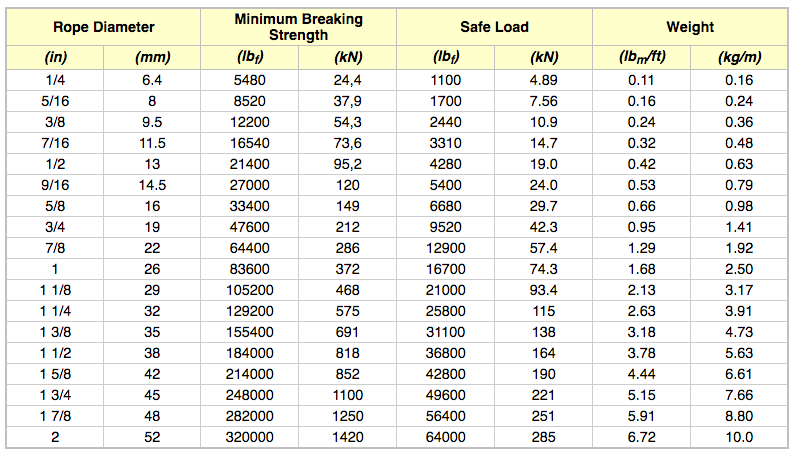
Selecting Wire Rope When selecting a wire rope to give the best service, there are four requirements which should be given consideration. A proper choice is made by correctly estimating the relative importance of these requirements and selecting a rope which has the qualities best suited to withstand the effects of continued use. The rope should possess:Strength sufficient to take care of the maximum load that may be applied, with a proper safety factor.
Strength Wire rope in service is subjected to several kinds of stresses. The stresses most frequently encountered are direct tension, stress due to acceleration, stress due to sudden or shock loads, stress due to bending, and stress resulting from several forces acting at one time. For the most part, these stresses can be converted into terms of simple tension, and a rope of approximately the correct strength can be chosen. As the strength of a wire rope is determined by its, size, grade and construction, these three factors should be considered.
Safety Factors The safety factor is the ratio of the strength of the rope to the working load. A wire rope with a strength of 10,000 pounds and a total working load of 2,000 pounds would be operating with a safety factor of five.
It is not possible to set safety factors for the various types of wire rope using equipment, as this factor can vary with conditions on individual units of equipment.
The proper safety factor depends not only on the loads applied, but also on the speed of operation, shock load applied, the type of fittings used for securing the rope ends, the acceleration and deceleration, the length of rope, the number, size and location of sheaves and drums, the factors causing abrasion and corrosion and the facilities for inspection.
Fatigue Fatigue failure of the wires in a wire rope is the result of the propagation of small cracks under repeated applications of bending loads. It occurs when ropes operate over comparatively small sheaves or drums. The repeated bending of the individual wires, as the rope bends when passing over the sheaves or drums, and the straightening of the individual wires, as the rope leaves the sheaves or drums, causing fatigue. The effect of fatigue on wires is illustrated by bending a wire repeatedly back and forth until it breaks.
The best means of preventing early fatigue of wire ropes is to use sheaves and drums of adequate size. To increase the resistance to fatigue, a rope of more flexible construction should be used, as increased flexibility is secured through the use of smaller wires.
Abrasive Wear The ability of a wire rope to withstand abrasion is determined by the size, the carbon and manganese content, the heat treatment of the outer wires and the construction of the rope. The larger outer wires of the less flexible constructions are better able to withstand abrasion than the finer outer wires of the more flexible ropes. The higher carbon and manganese content and the heat treatment used in producing wire for the stronger ropes, make the higher grade ropes better able to withstand abrasive wear than the lower grade ropes.
Effects of Bending All wire ropes, except stationary ropes used as guys or supports, are subjected to bending around sheaves or drums. The service obtained from wire ropes is, to a large extent, dependent upon the proper choice and location of the sheaves and drums about which it operates.
A wire rope may be considered a machine in which the individual elements (wires and strands) slide upon each other when the rope is bent. Therefore, as a prerequisite to the satisfactory operation of wire rope over sheaves and drums, the rope must be properly lubricated.
Loss of strength due to bending is caused by the inability of the individual strands and wires to adjust themselves to their changed position when the rope is bent. Tests made by the National Institute of Standards and Technology show that the rope strength decreases in a marked degree as the sheave diameter grows smaller with respect to the diameter of the rope. The loss of strength due to bending wire ropes over the sheaves found in common use will not exceed 6% and will usually be about 4%.
The bending of a wire rope is accompanied by readjustment in the positions of the strands and wires and results in actual bending of the wires. Repetitive flexing of the wires develops bending loads which, even though well within the elastic limit of the wires, set up points of stress concentration.
The fatigue effect of bending appears in the form of small cracks in the wires at these over-stressed foci. These cracks propagate under repeated stress cycles, until the remaining sound metal is inadequate to withstand the bending load. This results in broken wires showing no apparent contraction of cross section.
Experience has established the fact that from the service view-point, a very definite relationship exists between the size of the individual outer wires of a wire rope and the size of the sheave or drum about which it operates. Sheaves and drums smaller than 200 times the diameter of the outer wires will cause permanent set in a heavily loaded rope. Good practice requires the use of sheaves and drums with diameters 800 times the diameter of the outer wires in the rope for heavily loaded fast-moving ropes.
It is impossible to give a definite minimum size of sheave or drum about which a wire rope will operate with satisfactory results, because of the other factors affecting the useful life of the rope. If the loads are light or the speed slow, smaller sheaves and drums can be used without causing early fatigue of the wires than if the loads are heavy or the speed is fast. Reverse bends, where a rope is bent in one direction and then in the opposite direction, cause excessive fatigue and should be avoided whenever possible. When a reverse bend is necessary larger sheaves are required than would be the case if the rope were bent in one direction only.
Stretch of Wire Rope The stretch of a wire rope under load is the result of two components: the structural stretch and the elastic stretch. Structural stretch of wire rope is caused by the lengthening of the rope lay, compression of the core and adjustment of the wires and strands to the load placed upon the wire rope. The elastic stretch is caused by elongation of the wires.
The structural stretch varies with the size of core, the lengths of lays and the construction of the rope. This stretch also varies with the loads imposed and the amount of bending to which the rope is subjected. For estimating this stretch the value of one-half percent, or .005 times the length of the rope under load, gives an approximate figure. If loads are light, one-quarter percent or .0025 times the rope length may be used. With heavy loads, this stretch may approach one percent, or .01 times the rope length.
The elastic stretch of a wire rope is directly proportional to the load and the length of rope under load, and inversely proportional to the metallic area and modulus of elasticity. This applies only to loads that do not exceed the elastic limit of a wire rope. The elastic limit of stainless steel wire rope is approximately 60% of its breaking strength and for galvanized ropes it is approximately 50%.
Preformed Wire Ropes Preformed ropes differ from the standard, or non-preformed ropes, in that the individual wires in the strands and the strands in the rope are preformed, or pre-shaped to their proper shape before they are assembled in the finished rope.
This, in turn, results in preformed wire ropes having the following characteristics:They can be cut without the seizings necessary to retain the rope structure of non-preformed ropes.
They are substantially free from liveliness and twisting tendencies. This makes installation and handling easier, and lessens the likelihood of damage to the rope from kinking or fouling. Preforming permits the more general use of Lang lay and wire core constructions.
Removal of internal stresses increase resistance to fatigue from bending. This results in increased service where ability to withstand bending is the important requirement. It also permits the use of ropes with larger outer wires, when increased wear resistance is desired.
Outer wires will wear thinner before breaking, and broken wire ends will not protrude from the rope to injure worker’s hands, to nick and distort adjacent wires, or to wear sheaves and drums. Because of the fact that broken wire ends do not porcupine, they are not as noticeable as they are in non-preformed ropes. This necessitates the use of greater care when inspecting worn preformed ropes, to determine their true condition.

Wire rope is technically defined as multi-wire strands laid geometrically around a core while also used more generally as a term to classify multiple product families including aircraft cable, coated aircraft cable, general purpose wire rope, strand, rotation resistant wire rope, compacted/swaged wire rope, and cable laid wire rope.
Aircraft cable does not fit the definition of wire rope in the strictest sense as it does not have an independent core, but rather a strand core, in which the center is one of the strands that is laid with the outside strand layers. Aircraft cable is available in diameters 3/8" or less with breaking strengths similar to that of equal diameter independent wire rope core (IWRC) and is available in stainless steel and galvanized steel.
Wire rope can be galvanized via three processes. Listed from least corrosion-resistant to the most corrosion-resistant, they are electro-galvanizing, hot-dip galvanizing, and drawn-galvanizing. In addition to being the most corrosion-resistant types of galvanized wire rope, drawn-galvanized has another added benefit which is a breaking strength that is the same as bright wire rope does. Electro-galvanized and hot-dip galvanized wire rope have breaking strengths that are approximately 10% lower.
Wire rope is specified by the number of strands in the rope, the number of wires in each strand, and a description of the core’s material of construction. For example, the notation “6x7 FC” means that the rope has six strands with seven wires in each strand and a fiber core. Commonly used core designations include FC (fiber core), independent wire rope core (IWRC), wire strand core (WSC), and poly core (PC).
There are two elements to wire rope lubrication, the core, and outer strands. IWRC wire rope always has a lubricated core (unless specially ordered as otherwise). Bright wire rope always has lubricated outer strands. Galvanized wire rope can be manufactured in either dry finish or lubricated with respect to the outer strands. Typically stainless steel wire rope is manufactured with a lubricated IWRC and dry finish outer strands.

Asahi Intecc started in 1976 as a manufacturer of custom stainless-steel cables solutions and monofilament stainless wire, including small wire rope, strands and cables, plastic coated miniature cable, and miniature stainless cable assemblies for both medical device and non-medical applications.
1. IWSC (Independent Wire Strand Core): The core consists of a strand made of the same material as the outside strands of the wirerope. These strands are combined in configurations such as 3x7, 7x7 and 7x19. This structure can be used universally as a mechanical element and features excellent axial rigidity and bending flexibility.
2. IWRC (Independent Wire Rope Core): The core consists of a wire rope, around which the outside strands are twisted. The core wire rope and strands are combined in configurations such as {(7x7)+(1x19)x8} and others. This structure is used for mechanical elements that require high flexibility. As durability in the original form is low due to easy deformation under contact stress, these types are usually coated with a synthetic resin such as nylon.
In order to ensure the highest quality, we draw our own wire material in-house. Besides regular SS304 and SS316, Asahi also has its proprietary WHT (high-tensile strength) stainless-steel. We also work with tungsten and nitinol.
Asahi wire rope has been specifically designed for high flexibility and high strength. Different structure options give the possibility to meet your need as closely as possible. Example applications are angulation wires in endoscopic scopes, medical robotics forceps, etc.

Although Westech Rigging Supply strives to manufacture and sell the highest quality rigging and safety gear, use of the gear is dangerous if not used correctly by competent trained professionals. Westech Rigging Supply disclaims any liability resulting from the misuse of its rigging and safety gear. Please take a moment to more thoroughly review our disclaimer.
Westech Rigging Supply rigging and safety gear is only intended to be used by competent trained professionals. Misuse of the rigging and safety gear can result in serious injury up to and including loss of life. As such, Westech Rigging Supply disclaims liability for any misuse or incorrect product selection by our customers.
Stainless steel mechanical cable is, by its very design, corrosion resistant. Even setting aside mechanical cable for a moment, stainless steel, as a material choice in any use case, ensures impressive resistance to environmental elements that would corrode this popular iron and carbon alloy. However, for all its corrosion-resistant properties, even stainless steel remains at risk of oxidation when applied to a harsh environment. It is therefore precisely when stainless steel requires additional protection from hostile conditions that cable design engineers may choose to perform an operation known as passivation to the stainless steel cable.
Passivation extends the life and quality of a stainless steel cable (and/or wire rope) by maximizing its corrosion resistance. This maximizing process involves treating the surface of the stainless steel mechanical cable with either nitric acid or citric acid, which removes free iron from the cable filament surfaces themselves. The acid removes the iron particles that exist on the surface layer of the cable, which may cause oxidation if certain conditions are present. Without passivation, by way of comparison, the free iron in the stainless steel cable would react with the oxygen in the air to ultimately introduce rust to the cable. Passivation removes this unwanted iron, leaving the critical element chromium to act as the protectant against oxidation.
Once the passivated cable is then exposed to oxygen, the oxygen bonds freely with the surface, creating an oxide layer that inherently protects the cable. The oxygen now binds to the surface instead of oxidizing. So the once potentially hostile and harmful element oxygen is now free to make unfettered contact with the stainless steel cable without consequence.
However, as protected as passivation leaves stainless steel cable, engineers must still treat the cable with care. Passivation creates a microlayer of protection against corrosion, but this surface treatment can be inadvertently stripped by the presence of friction, or other surface penetrant. So when installing, for instance, passivated stainless steel cable into a motion control system, design engineers must mitigate any potential sources of unwanted friction or other types of damage to the surface of the cable itself.
When passivating stainless steel cable, the cable is first cleaned through a process known as ultrasonic cleaning. Ultrasonic cleaning is the process of literally bathing the stainless steel cable in a solution where high frequency vibrations resonate the cable. These vibrating forces effectively shake free any unwanted particulate in anticipation of the passivation process.
Because passivation is designed to increase corrosion resistance to the surface of the cable filaments, it’s critical to understand that the role of ultrasonic cleaning is therefore to expose the most amount of cable surface area possible to later passivate. Once the stainless steel cable is ultrasonically cleaned, passivation can begin.
Although stainless steel cable is ideally suited to passivation, the acid used and degree to which the cable is exposed to it is determined by the grade of stainless steel. 304 stainless steel, for example, has a 18% chromium content, whereas 316 has 16% of the same element. Because of this subtle difference in material components, each will tolerate passivation acids differently. So while passivation is ideal for stainless steel, the acids used, as well as the exposure to them is decided on a case-by-case basis.
Take tungsten cable, for instance. It is not necessary for tungsten mechanical cable to be passivated because wolfram does not contain free iron. Remembering that it is the presence of free iron that puts stainless steel cable at risk of corrosion, wolfram simply does not possess the same molecular components and thus, the same risks.
If tungsten was dipped in passivating acids, by way of comparing it to stainless steel cable, it might erode the material to the detriment of its strength and integrity.
What’s more, galvanized steel cable likewise does not require passivation because galvanized cable, by design, contains an added layer of zinc. This protective layer of elementary material provides comparable oxidation resistance for galvanized steel cable that’s similar to that which is achieved with passivated stainless steel cable.
These industries generally possess moisture-rich environments that put stainless steel cable in danger of corrosion were it not passivated. Moreover, anywhere oxygen is present, stainless steel cable performs best when passivated.
Passivation does not affect the structural integrity of the stainless steel because the process only affects a negligible amount of surface material. When in doubt, consult your cable design engineer to ensure that the cable application under consideration requires or benefits from passivation.
Sava possesses decades of in-house engineering, quality and production expertise to accommodate any stainless steel passivation project. Contact us for more information about cable passivation.

At Carl Stahl Sava Industries, our steel mechanical cable choices include 304 and 316 stainless steel and galvanized steel cable. Sava is both a wire rope supplier and a wire rope manufacturer that is able to work withexotic steel alternatives upon request, both stainless steel and galvanized steel mechanical cable offer distinct benefits, depending upon the application. Read on to learn the differences between galvanized vs. stainless steel wire ropeand determine which custom wire rope will better serve your application requirements.
One of the greatest benefits of stainless steel wire rope is that it is suitable for nearly any application. While it may have a slightly higher cost than galvanized steel cable, stainless steel cable provides customers with greater ROI and maintains its high-strength qualities over its lifespan under most conditions. While not as strong as tungsten or tolerant of excessive temperatures, stainless steel mechanical wire rope is an incredibly effective cable construction material.
Stainless steel has high corrosion resistance due to it being treated with chromium. This additional element makes stainless steel suitable for use in moist environments, even when harmful salty conditions are present. Specifically in marine environments, for instance, stainless steel wire rope can be used for years without corroding. And in the medical devices field, stainless steel is commonly the metal of choice for many medical device instruments like endoscopes because of its high sanitization level and durability over many cycles makes it ideal.
Galvanized steel is steel that has been dipped in a zinc coating, which gives it good corrosion-resistant qualities. But even with the addition of zinc, galvanized wire rope’s strength is weaker than stainless steel because of the presence of chromium, making the cable stronger and more tolerant of corrosive elements like saltwater. Galvanized cable will rust and corrode if salty wet conditions are present. And like stainless steel, galvanized steel cable ends will also weld together if they make contact with one another.
Galvanized steel cable is often found in industrial applications, since items may brush up against the wire rope in the field, which again, are environmental conditions that galvanized steel tolerates quite well over time. For this and other reasons, Galvanized steel wire rope works exceptionally well in aerospace applications.
Stainless steel wire rope is a cost-effective solution that works across a range of applications, is impervious to salty wetness and is stronger than galvanized steel cable. But galvanized steel wire rope is corrosion-resistant, except when salt is present and tolerates contact with itself far better than stainless steel cable.
It"s important to remember that since each application has unique needs, these comparisons are general guidelines. Contact Sava today to discuss your project, so we can help you determine whether a stainless steel wire rope or galvanized steel wire rope is best for your cable manufacturing needs.


 8613371530291