
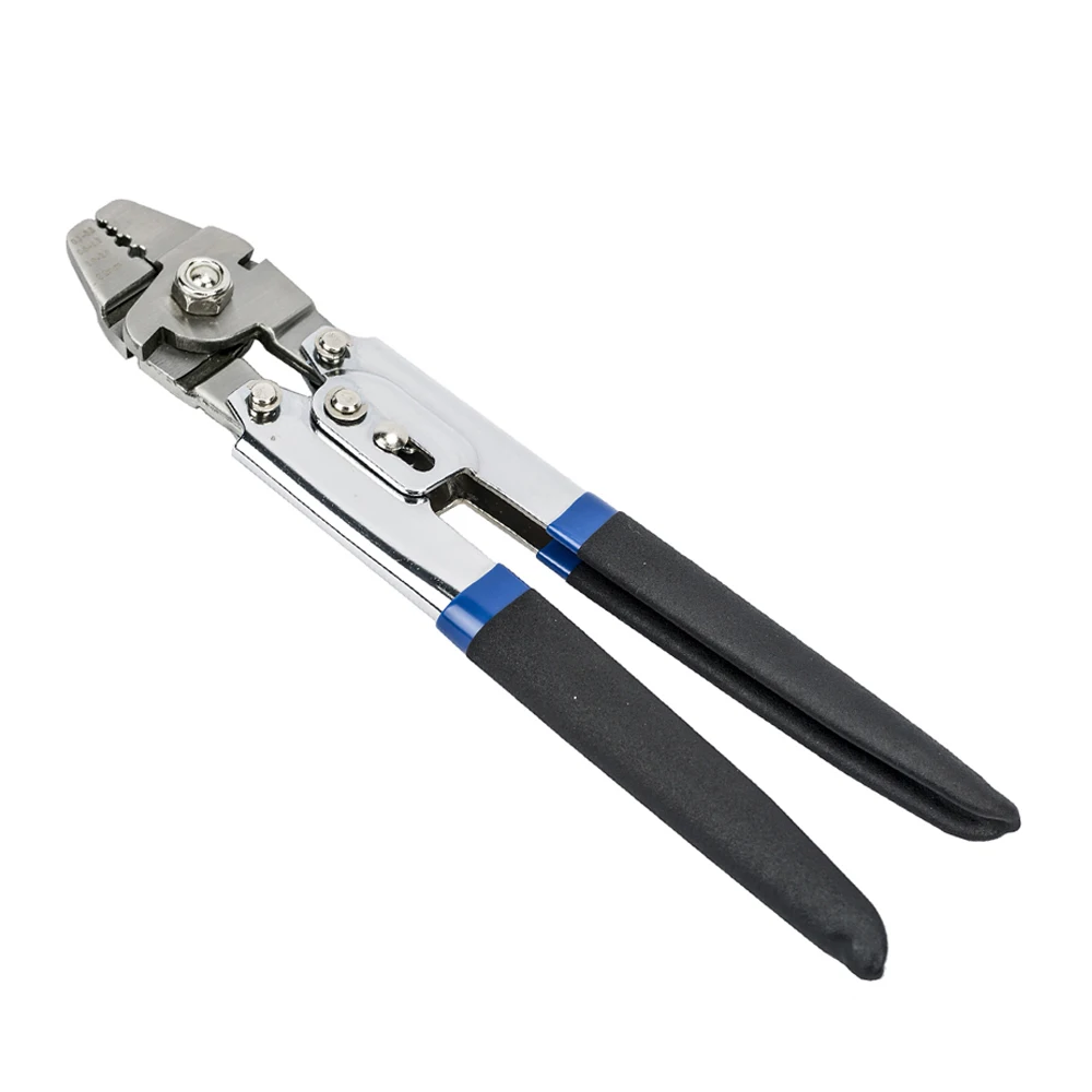
stainless steel wire rope crimping tool free sample

1x19 Type 316 stainless steel wire rope is primarily used for deck railings, marine rigging and boat lifelines, as well as architectural structural rigging. The 19-wire composition makes this wire very stiff. It has a smooth, clean finish for a great-looking railing cable. Stainless steel wire offers maximum corrosion resistance and durability. The 1x19 construction does not allow for kinks or bends.

1x19 Type 316 stainless steel wire rope is primarily used for deck railings, marine rigging and boat lifelines, as well as architectural structural rigging. The 19-wire composition makes this wire very stiff. It has a smooth, clean finish for a great-looking railing cable. Stainless steel wire offers maximum corrosion resistance and durability. The 1x19 construction does not allow for kinks or bends.

Stainless steel mechanical cable is, by its very design, corrosion resistant. Even setting aside mechanical cable for a moment, stainless steel, as a material choice in any use case, ensures impressive resistance to environmental elements that would corrode this popular iron and carbon alloy. However, for all its corrosion-resistant properties, even stainless steel remains at risk of oxidation when applied to a harsh environment. It is therefore precisely when stainless steel requires additional protection from hostile conditions that cable design engineers may choose to perform an operation known as passivation to the stainless steel cable.
Passivation extends the life and quality of a stainless steel cable (and/or wire rope) by maximizing its corrosion resistance. This maximizing process involves treating the surface of the stainless steel mechanical cable with either nitric acid or citric acid, which removes free iron from the cable filament surfaces themselves. The acid removes the iron particles that exist on the surface layer of the cable, which may cause oxidation if certain conditions are present. Without passivation, by way of comparison, the free iron in the stainless steel cable would react with the oxygen in the air to ultimately introduce rust to the cable. Passivation removes this unwanted iron, leaving the critical element chromium to act as the protectant against oxidation.
Once the passivated cable is then exposed to oxygen, the oxygen bonds freely with the surface, creating an oxide layer that inherently protects the cable. The oxygen now binds to the surface instead of oxidizing. So the once potentially hostile and harmful element oxygen is now free to make unfettered contact with the stainless steel cable without consequence.
However, as protected as passivation leaves stainless steel cable, engineers must still treat the cable with care. Passivation creates a microlayer of protection against corrosion, but this surface treatment can be inadvertently stripped by the presence of friction, or other surface penetrant. So when installing, for instance, passivated stainless steel cable into a motion control system, design engineers must mitigate any potential sources of unwanted friction or other types of damage to the surface of the cable itself.
When passivating stainless steel cable, the cable is first cleaned through a process known as ultrasonic cleaning. Ultrasonic cleaning is the process of literally bathing the stainless steel cable in a solution where high frequency vibrations resonate the cable. These vibrating forces effectively shake free any unwanted particulate in anticipation of the passivation process.
Because passivation is designed to increase corrosion resistance to the surface of the cable filaments, it’s critical to understand that the role of ultrasonic cleaning is therefore to expose the most amount of cable surface area possible to later passivate. Once the stainless steel cable is ultrasonically cleaned, passivation can begin.
Although stainless steel cable is ideally suited to passivation, the acid used and degree to which the cable is exposed to it is determined by the grade of stainless steel. 304 stainless steel, for example, has a 18% chromium content, whereas 316 has 16% of the same element. Because of this subtle difference in material components, each will tolerate passivation acids differently. So while passivation is ideal for stainless steel, the acids used, as well as the exposure to them is decided on a case-by-case basis.
Take tungsten cable, for instance. It is not necessary for tungsten mechanical cable to be passivated because wolfram does not contain free iron. Remembering that it is the presence of free iron that puts stainless steel cable at risk of corrosion, wolfram simply does not possess the same molecular components and thus, the same risks.
If tungsten was dipped in passivating acids, by way of comparing it to stainless steel cable, it might erode the material to the detriment of its strength and integrity.
What’s more, galvanized steel cable likewise does not require passivation because galvanized cable, by design, contains an added layer of zinc. This protective layer of elementary material provides comparable oxidation resistance for galvanized steel cable that’s similar to that which is achieved with passivated stainless steel cable.
These industries generally possess moisture-rich environments that put stainless steel cable in danger of corrosion were it not passivated. Moreover, anywhere oxygen is present, stainless steel cable performs best when passivated.
Passivation does not affect the structural integrity of the stainless steel because the process only affects a negligible amount of surface material. When in doubt, consult your cable design engineer to ensure that the cable application under consideration requires or benefits from passivation.
Sava possesses decades of in-house engineering, quality and production expertise to accommodate any stainless steel passivation project. Contact us for more information about cable passivation.

Wire rope consists of several strands of steel wire twisted into a helix. Most wire ropes are made from uncoated high-carbon steel wire, but they can also be made from galvanized wire or stainless steel wire. They are available in diameters ranging from 1/32 to 5 inches or more.
Wire ropes are used dynamically for lifting and hoisting in cranes and elevators. They’re also used to transmit mechanical force. For example, wire ropes connect the control surfaces of some airplanes to levers and pedals in the cockpit. In automobiles, wire ropes can be used to actuate the parking brake, gear shifter and throttle.
Metal sleeves are usually applied to each end of a wire rope to prevent it from fraying and to help connect the rope to a mechanism or structure. Metal sleeves can also be used to splice two wire ropes together.
While presses can certainly apply enough power to crimp a sleeve to a wire rope, they are stationary. They can’t be used to make terminations in situ.
Manually operated hand tools are portable, but there’s a limit to how much force they can apply. Moreover, repeated actuation in a production environment can be an ergonomic issue.
Fabco-Air’s 300 series of pneumatic tools achieve tremendous crimping power from force-multiplying air cylinders combined with cam-operated jaws. The power cylinder has three pistons attached to a common shaft. Each piston is isolated within its own chamber by means of baffles integral with the outer cylinder wall. Special internal porting through the rod allows air pressure to simultaneously energize all pistons and transmit more than 1,700 pounds force directly to the cam and power head.
Force is increased through the cam and jaws to approximately 4,000 pounds at a distance of 1 inch from the tool and approximately 2,500 pounds at a distance of 2 inches.
They are available in both handheld and bench-mounted models, so engineers can bring the tool to the work or centralize assembly work at a bench. The units are lightweight and portable, so assembly lines can be readily moved and adjusted to optimize production.
The tools can handle wires ranging from 1/32 to 3/8 inch in diameter. They run on standard shop air pressure of 85 to 95 psi. Dual triggers allow the tool to be operated using either the left or right hand, with or without gloves.
A wide selection of single-groove and multi-groove power heads is available. The power heads can be interchanged in less than a minute on either bench-mounted or portable tools.
For safety, the tool operates in a multistep process. Depressing a white button at the top of the handle opens the jaws to receive the workpiece. Releasing the button allows the jaws to spring closed and grip the parts securely. Pulling either of the red triggers releases a lock so that the valve can be tripped by squeezing the index finger. This actuates the power cylinder and drives the cam-operated jaws into their closed crimping position.
The bench-mounted version operates in much the same way. Like the handheld model, the bench model is equipped with spring-loaded crimping jaws that are normally closed for safety. The bench model is actuated via a foot switch. Pressure on valve A opens the jaws so the wire and sleeve assembly can be inserted. Releasing valve A allows the crimp jaws to close lightly and hold the assembly securely in place. Foot pressure on valve B activates the crimping cycle.
The benchtop tool’s control box includes a pressure-sensing valve that can be adjusted for various crimp pressures. If the supply pressure should fall below the sensing valve’s pressure setting, the valve will not provide a “crimp” signal to the tool. This prevents the tool from making a bad crimp and ruining the parts.
Larger cables may require higher forces for sufficient crimping. An optional booster accessory is available to increase air pressure to the tool to an acceptable level.
Lap or running splices can be made with oval sleeves when lengthening cable or making grommet slings. Oval sleeves are widely available in a variety of materials, including aluminum, copper, zinc-copper, tin-copper and stainless steel. Two sleeves are typically needed to develop a splice equal to the breaking strength of the wire.
To make a splice, pull one end of each cable through both sleeves. Leave a little space between the sleeves to allow for extrusion of the sleeves during crimping. Also, the finished crimp should have some space between sleeves to provide cable flexibility. Line up the sleeve between the tool jaws with the long axis crosswise to the jaws.
Our custom-designed Hydraulic crimping tool is made with high-quality steel materials for super durability, strength, and long-lasting performance. With our upgraded hydraulic crimper tool + cable cutter CT01, it is easier than ever to bid adieu to frayed cable ends and unwanted pieces. So, switch to our cable rail crimping tool and save your project time. Our hand-held pair of cable cutters are suitable for most installations or upgrade to a bench-mount option for large commercial projects, or repeat installations over multiple projects.
Our products are designed to offer comfort to our customers when using our products. The comfortable ergonomic cushioned handle of our cable rail crimping tools makes it easy to grip and control.
From heavy-duty cable tools to custom hydraulic crimper tools, we offer a gamut of cable crimper tools that will keep you covered at economical prices.
For us, our customers come first, and this is the core reason that we offer customized services to keep their content. So, get your hands on the best crimper and cable tools at budget-friendly prices.
Our fork and jaw end fittings must be machine swaged for proper hold strength. Lexco takes pride in our assembly work and will quote any assembly you need per your specification or design print.
Lexco® Cable supplies both commercial grade and MIL SPEC (MS20667) fork ends. Typically machined from 304 stainless steel, they are available in various sizes to accommodate cable from 1/16” to 1” in diameter.
Commercial and military grade fork ends must be machine swaged for proper hold strength. Please contacta Lexco® sales representative to receive an assembly quote.

In stricter senses, the term wire rope refers to a diameter larger than 9.5 mm (3⁄8 in), with smaller gauges designated cable or cords.wrought iron wires were used, but today steel is the main material used for wire ropes.
Historically, wire rope evolved from wrought iron chains, which had a record of mechanical failure. While flaws in chain links or solid steel bars can lead to catastrophic failure, flaws in the wires making up a steel cable are less critical as the other wires easily take up the load. While friction between the individual wires and strands causes wear over the life of the rope, it also helps to compensate for minor failures in the short run.
Wire ropes were developed starting with mining hoist applications in the 1830s. Wire ropes are used dynamically for lifting and hoisting in cranes and elevators, and for transmission of mechanical power. Wire rope is also used to transmit force in mechanisms, such as a Bowden cable or the control surfaces of an airplane connected to levers and pedals in the cockpit. Only aircraft cables have WSC (wire strand core). Also, aircraft cables are available in smaller diameters than wire rope. For example, aircraft cables are available in 1.2 mm (3⁄64 in) diameter while most wire ropes begin at a 6.4 mm (1⁄4 in) diameter.suspension bridges or as guy wires to support towers. An aerial tramway relies on wire rope to support and move cargo overhead.
Modern wire rope was invented by the German mining engineer Wilhelm Albert in the years between 1831 and 1834 for use in mining in the Harz Mountains in Clausthal, Lower Saxony, Germany.chains, such as had been used before.
Wilhelm Albert"s first ropes consisted of three strands consisting of four wires each. In 1840, Scotsman Robert Stirling Newall improved the process further.John A. Roebling, starting in 1841suspension bridge building. Roebling introduced a number of innovations in the design, materials and manufacture of wire rope. Ever with an ear to technology developments in mining and railroading, Josiah White and Erskine Hazard, principal ownersLehigh Coal & Navigation Company (LC&N Co.) — as they had with the first blast furnaces in the Lehigh Valley — built a Wire Rope factory in Mauch Chunk,Pennsylvania in 1848, which provided lift cables for the Ashley Planes project, then the back track planes of the Summit Hill & Mauch Chunk Railroad, improving its attractiveness as a premier tourism destination, and vastly improving the throughput of the coal capacity since return of cars dropped from nearly four hours to less than 20 minutes. The decades were witness to a burgeoning increase in deep shaft mining in both Europe and North America as surface mineral deposits were exhausted and miners had to chase layers along inclined layers. The era was early in railroad development and steam engines lacked sufficient tractive effort to climb steep slopes, so incline plane railways were common. This pushed development of cable hoists rapidly in the United States as surface deposits in the Anthracite Coal Region north and south dove deeper every year, and even the rich deposits in the Panther Creek Valley required LC&N Co. to drive their first shafts into lower slopes beginning Lansford and its Schuylkill County twin-town Coaldale.
The German engineering firm of Adolf Bleichert & Co. was founded in 1874 and began to build bicable aerial tramways for mining in the Ruhr Valley. With important patents, and dozens of working systems in Europe, Bleichert dominated the global industry, later licensing its designs and manufacturing techniques to Trenton Iron Works, New Jersey, USA which built systems across America. Adolf Bleichert & Co. went on to build hundreds of aerial tramways around the world: from Alaska to Argentina, Australia and Spitsbergen. The Bleichert company also built hundreds of aerial tramways for both the Imperial German Army and the Wehrmacht.
In the last half of the 19th century, wire rope systems were used as a means of transmitting mechanical powercable cars. Wire rope systems cost one-tenth as much and had lower friction losses than line shafts. Because of these advantages, wire rope systems were used to transmit power for a distance of a few miles or kilometers.
Steel wires for wire ropes are normally made of non-alloy carbon steel with a carbon content of 0.4 to 0.95%. The very high strength of the rope wires enables wire ropes to support large tensile forces and to run over sheaves with relatively small diameters.
In the mostly used parallel lay strands, the lay length of all the wire layers is equal and the wires of any two superimposed layers are parallel, resulting in linear contact. The wire of the outer layer is supported by two wires of the inner layer. These wires are neighbors along the whole length of the strand. Parallel lay strands are made in one operation. The endurance of wire ropes with this kind of strand is always much greater than of those (seldom used) with cross lay strands. Parallel lay strands with two wire layers have the construction Filler, Seale or Warrington.
In principle, spiral ropes are round strands as they have an assembly of layers of wires laid helically over a centre with at least one layer of wires being laid in the opposite direction to that of the outer layer. Spiral ropes can be dimensioned in such a way that they are non-rotating which means that under tension the rope torque is nearly zero. The open spiral rope consists only of round wires. The half-locked coil rope and the full-locked coil rope always have a centre made of round wires. The locked coil ropes have one or more outer layers of profile wires. They have the advantage that their construction prevents the penetration of dirt and water to a greater extent and it also protects them from loss of lubricant. In addition, they have one further very important advantage as the ends of a broken outer wire cannot leave the rope if it has the proper dimensions.
Stranded ropes are an assembly of several strands laid helically in one or more layers around a core. This core can be one of three types. The first is a fiber core, made up of synthetic material or natural fibers like sisal. Synthetic fibers are stronger and more uniform but cannot absorb much lubricant. Natural fibers can absorb up to 15% of their weight in lubricant and so protect the inner wires much better from corrosion than synthetic fibers do. Fiber cores are the most flexible and elastic, but have the downside of getting crushed easily. The second type, wire strand core, is made up of one additional strand of wire, and is typically used for suspension. The third type is independent wire rope core (IWRC), which is the most durable in all types of environments.ordinary lay rope if the lay direction of the wires in the outer strands is in the opposite direction to the lay of the outer strands themselves. If both the wires in the outer strands and the outer strands themselves have the same lay direction, the rope is called a lang lay rope (from Dutch langslag contrary to kruisslag,Regular lay means the individual wires were wrapped around the centers in one direction and the strands were wrapped around the core in the opposite direction.
Multi-strand ropes are all more or less resistant to rotation and have at least two layers of strands laid helically around a centre. The direction of the outer strands is opposite to that of the underlying strand layers. Ropes with three strand layers can be nearly non-rotating. Ropes with two strand layers are mostly only low-rotating.
Stationary ropes, stay ropes (spiral ropes, mostly full-locked) have to carry tensile forces and are therefore mainly loaded by static and fluctuating tensile stresses. Ropes used for suspension are often called cables.
Track ropes (full locked ropes) have to act as rails for the rollers of cabins or other loads in aerial ropeways and cable cranes. In contrast to running ropes, track ropes do not take on the curvature of the rollers. Under the roller force, a so-called free bending radius of the rope occurs. This radius increases (and the bending stresses decrease) with the tensile force and decreases with the roller force.
Wire rope slings (stranded ropes) are used to harness various kinds of goods. These slings are stressed by the tensile forces but first of all by bending stresses when bent over the more or less sharp edges of the goods.
Technical regulations apply to the design of rope drives for cranes, elevators, rope ways and mining installations. Factors that are considered in design include:
Donandt force (yielding tensile force for a given bending diameter ratio D/d) - strict limit. The nominal rope tensile force S must be smaller than the Donandt force SD1.
The wire ropes are stressed by fluctuating forces, by wear, by corrosion and in seldom cases by extreme forces. The rope life is finite and the safety is only ensured by inspection for the detection of wire breaks on a reference rope length, of cross-section loss, as well as other failures so that the wire rope can be replaced before a dangerous situation occurs. Installations should be designed to facilitate the inspection of the wire ropes.
Lifting installations for passenger transportation require that a combination of several methods should be used to prevent a car from plunging downwards. Elevators must have redundant bearing ropes and a safety gear. Ropeways and mine hoistings must be permanently supervised by a responsible manager and the rope must be inspected by a magnetic method capable of detecting inner wire breaks.
The end of a wire rope tends to fray readily, and cannot be easily connected to plant and equipment. There are different ways of securing the ends of wire ropes to prevent fraying. The common and useful type of end fitting for a wire rope is to turn the end back to form a loop. The loose end is then fixed back on the wire rope. Termination efficiencies vary from about 70% for a Flemish eye alone; to nearly 90% for a Flemish eye and splice; to 100% for potted ends and swagings.
When the wire rope is terminated with a loop, there is a risk that it will bend too tightly, especially when the loop is connected to a device that concentrates the load on a relatively small area. A thimble can be installed inside the loop to preserve the natural shape of the loop, and protect the cable from pinching and abrading on the inside of the loop. The use of thimbles in loops is industry best practice. The thimble prevents the load from coming into direct contact with the wires.
A wire rope clip, sometimes called a clamp, is used to fix the loose end of the loop back to the wire rope. It usually consists of a U-bolt, a forged saddle, and two nuts. The two layers of wire rope are placed in the U-bolt. The saddle is then fitted to the bolt over the ropes (the saddle includes two holes to fit to the U-bolt). The nuts secure the arrangement in place. Two or more clips are usually used to terminate a wire rope depending on the diameter. As many as eight may be needed for a 2 in (50.8 mm) diameter rope.
The mnemonic "never saddle a dead horse" means that when installing clips, the saddle portion of the assembly is placed on the load-bearing or "live" side, not on the non-load-bearing or "dead" side of the cable. This is to protect the live or stress-bearing end of the rope against crushing and abuse. The flat bearing seat and extended prongs of the body are designed to protect the rope and are always placed against the live end.
An eye splice may be used to terminate the loose end of a wire rope when forming a loop. The strands of the end of a wire rope are unwound a certain distance, then bent around so that the end of the unwrapped length forms an eye. The unwrapped strands are then plaited back into the wire rope, forming the loop, or an eye, called an eye splice.
A Flemish eye, or Dutch Splice, involves unwrapping three strands (the strands need to be next to each other, not alternates) of the wire and keeping them off to one side. The remaining strands are bent around, until the end of the wire meets the "V" where the unwrapping finished, to form the eye. The strands kept to one side are now re-wrapped by wrapping from the end of the wire back to the "V" of the eye. These strands are effectively rewrapped along the wire in the opposite direction to their original lay. When this type of rope splice is used specifically on wire rope, it is called a "Molly Hogan", and, by some, a "Dutch" eye instead of a "Flemish" eye.
Swaging is a method of wire rope termination that refers to the installation technique. The purpose of swaging wire rope fittings is to connect two wire rope ends together, or to otherwise terminate one end of wire rope to something else. A mechanical or hydraulic swager is used to compress and deform the fitting, creating a permanent connection. Threaded studs, ferrules, sockets, and sleeves are examples of different swaged terminations.
A wedge socket termination is useful when the fitting needs to be replaced frequently. For example, if the end of a wire rope is in a high-wear region, the rope may be periodically trimmed, requiring the termination hardware to be removed and reapplied. An example of this is on the ends of the drag ropes on a dragline. The end loop of the wire rope enters a tapered opening in the socket, wrapped around a separate component called the wedge. The arrangement is knocked in place, and load gradually eased onto the rope. As the load increases on the wire rope, the wedge become more secure, gripping the rope tighter.
Poured sockets are used to make a high strength, permanent termination; they are created by inserting the wire rope into the narrow end of a conical cavity which is oriented in-line with the intended direction of strain. The individual wires are splayed out inside the cone or "capel", and the cone is then filled with molten lead-antimony-tin (Pb80Sb15Sn5) solder or "white metal capping",zincpolyester resin compound.
Donald Sayenga. "Modern History of Wire Rope". History of the Atlantic Cable & Submarine Telegraphy (atlantic-cable.com). Archived from the original on 3 February 2014. Retrieved 9 April 2014.

NCA Cable Assemblies offers a full line of wire rope and aircraft cable end fittings. We are the leader in custom wire rope hardware or aircraft cable hardware. Our fittings are designed for installation directly onto cable or wire rope by crimping, clamping, swaging,or Speltering.Most fitting types are available in numerous sizes and materials of construction to meet the needs of nearly any customer application. Wire rope lanyard assemblies include: stamped eyelets, stop sleeves, ball shanks, strap eye and forks, fork ends, wire rope clips, thimbles, threaded studs, tabs, marine eyes, snap and winch hooks, oval sleeves for cable loops.

Wire rope thimbles also known as cable thimbles, are used for making reinforce loop(eyelet) with grips, clips or clamps by preventing fraying caused by friction at the bearing anchor point to protect and extend the service life of the wire rope or sling. They are just one of the many types of wire rope fittings (ferrules, wire rope clips, terminals, etc.).
Wire rope thimbles are available in a variety of strengths and materials(carbon steel and stainless steel, see our post on Surface Finish: 4 Common Types You Should Know) but mainly they come in two different duty grades.
If you use it in high moisture or corrosive environments, recommend our stainless steel wire rope thimbles which can offer resistance to corrosion on the surface, particularly in marine applications.
Simply wrap the end of the wire rope around the outer groove of the thimble, lace the dead end of the wire rope past the U-bolt of the wire rope grips or a wire rope ferrule crimp to hold onto the bearing anchor point at the end of the thimble to prevent fraying caused by friction.
Once in place, put another wire rope clip as near the loop you just wrapped over the thimble. Turn nuts firmly but do not yet tighten to the proper torque, we recommend using a crimping/swaging tool to compress the ferrule firmly onto the rope to hold your thimble loop securely.
Alternatively, you can use a wire rope ferrule crimp to secure your thimble in place. this method is quick and easy to install. For further information on installation using a wire rope ferrule please – click here
Wire rope thimbles are used in conjunction with cable and rope to protect the eyes and will allow for smooth rope guiding around natural curves. So that the most important thing is to make sure the thimble eye securely fastened. Here are some tips for correctly using wire rope thimble:
Make sure that the cable thimbles size properly and securely fastened in the eye of the loop, not too loose or too tighten, so they can create an extra layer of support to connect with other properly sized rigging fittings.
While you are using a vinyl coated cable, you should multiply the actual size of the cable, usually use a larger size thimble than normal, for the actual diameter is the thickness of the vinyl coating plus the inside wire rope diameter. For example, if you are using a 5/16″ vinyl coated cable that is coated to 3/8″ diameter, you’d want to use a 3/8″ wire rope thimble.


 8613371530291