
stainless steel wire rope terminations free sample

At Stainless Cable Solutions, our termination fittings are manufactured from the most superior-grade 316 stainless steel, following the most precise military specifications and quality control standards. Our process has been honed over a decade of experience and expertise, resulting in unmatched durability that keeps them strong, visually appealing and capable of withstanding the many tests of time.
Our stainless button terminals feature a modern look and are perfect in a wide range of wood and metal post applications. We"ve designed them for minimal physical and visual interference, with the button only visible from the outside face of your post.
Perfect for face-mounting to buildings or wooden post applications. SCS stainless deck toggle terminals serve as a perfect solution for many angled applications. The hardware seamlessly articulates to the pitch of your stairs, and can also be attached to steel posts by drilling or tapping.
Whether you"re attaching terminals directly into wood with an eye bolt, or looking for terminals that articulate the specific pitch of stairs, Stainless Cable Solutions Jaw Toggle Terminals are easy to work with and designed for decades of reliability. They can also be connected to steel posts with tabs or gusset plates.
If you"re working with hollow core posts, our Lock T Terminal is an excellent choice. This popular 316 stainless steel termination fitting is only available for 1/8" cable, and SCS will swage the hardware for your convenience. Bend the cable to 90 degrees before inserting into the post, and the Lock T mollies on the inside for an economical solution on stair applications and 90 degree corners.
For additional details on our complete line of premium stainless termination fittings, contact Stainless Cable Solutions today. See why SCS is “The Clear Choice" among so many of today’s homeowners and custom builders.
Our fork and jaw end fittings must be machine swaged for proper hold strength. Lexco takes pride in our assembly work and will quote any assembly you need per your specification or design print.
Lexco® Cable supplies both commercial grade and MIL SPEC (MS20667) fork ends. Typically machined from 304 stainless steel, they are available in various sizes to accommodate cable from 1/16” to 1” in diameter.
Commercial and military grade fork ends must be machine swaged for proper hold strength. Please contacta Lexco® sales representative to receive an assembly quote.

Wire rope and cable are each considered a “machine”. The configuration and method of manufacture combined with the proper selection of material when designed for a specific purpose enables a wire rope or cable to transmit forces, motion and energy in some predetermined manner and to some desired end.
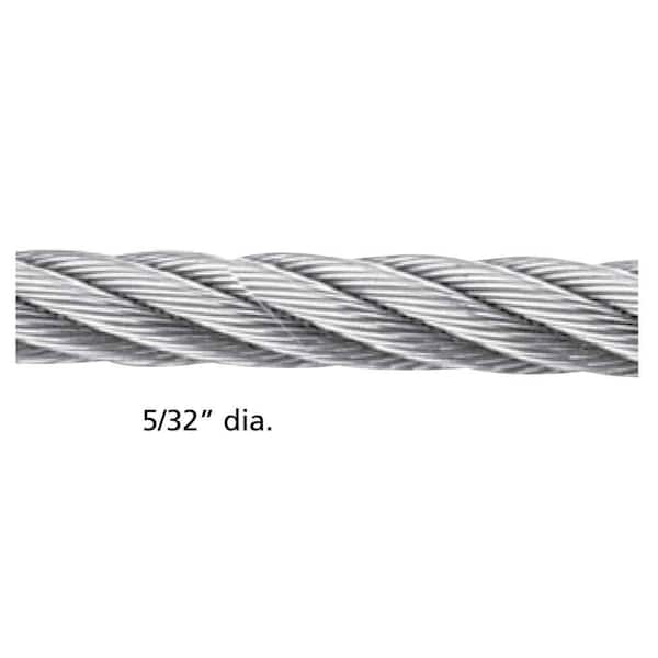
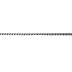
Two or more wires concentrically laid around a center wire is called a strand. It may consist of one or more layers. Typically, the number of wires in a strand is 7, 19 or 37. A group of strands laid around a core would be called a cable or wire rope. In terms of product designation, 7 strands with 19 wires in each strand would be a 7×19 cable: 7 strands with 7 wires in each strand would be a 7×7 cable.
Materials Different applications for wire rope present varying demands for strength, abrasion and corrosion resistance. In order to meet these requirements, wire rope is produced in a number of different materials.
Stainless Steel This is used where corrosion is a prime factor and the cost increase warrants its use. The 18% chromium, 8% nickel alloy known as type 302 is the most common grade accepted due to both corrosion resistance and high strength. Other types frequently used in wire rope are 304, 305, 316 and 321, each having its specific advantage over the other. Type 305 is used where non-magnetic properties are required, however, there is a slight loss of strength.
Galvanized Carbon Steel This is used where strength is a prime factor and corrosion resistance is not great enough to require the use of stainless steel. The lower cost is usually a consideration in the selection of galvanized carbon steel. Wires used in these wire ropes are individually coated with a layer of zinc which offers a good measure of protection from corrosive elements.
Cable Construction The greater the number of wires in a strand or cable of a given diameter, the more flexibility it has. A 1×7 or a 1×19 strand, having 7 and 19 wires respectively, is used principally as a fixed member, as a straight linkage, or where flexing is minimal.
Selecting Wire Rope When selecting a wire rope to give the best service, there are four requirements which should be given consideration. A proper choice is made by correctly estimating the relative importance of these requirements and selecting a rope which has the qualities best suited to withstand the effects of continued use. The rope should possess:Strength sufficient to take care of the maximum load that may be applied, with a proper safety factor.
Strength Wire rope in service is subjected to several kinds of stresses. The stresses most frequently encountered are direct tension, stress due to acceleration, stress due to sudden or shock loads, stress due to bending, and stress resulting from several forces acting at one time. For the most part, these stresses can be converted into terms of simple tension, and a rope of approximately the correct strength can be chosen. As the strength of a wire rope is determined by its, size, grade and construction, these three factors should be considered.
Safety Factors The safety factor is the ratio of the strength of the rope to the working load. A wire rope with a strength of 10,000 pounds and a total working load of 2,000 pounds would be operating with a safety factor of five.
It is not possible to set safety factors for the various types of wire rope using equipment, as this factor can vary with conditions on individual units of equipment.
The proper safety factor depends not only on the loads applied, but also on the speed of operation, shock load applied, the type of fittings used for securing the rope ends, the acceleration and deceleration, the length of rope, the number, size and location of sheaves and drums, the factors causing abrasion and corrosion and the facilities for inspection.
Fatigue Fatigue failure of the wires in a wire rope is the result of the propagation of small cracks under repeated applications of bending loads. It occurs when ropes operate over comparatively small sheaves or drums. The repeated bending of the individual wires, as the rope bends when passing over the sheaves or drums, and the straightening of the individual wires, as the rope leaves the sheaves or drums, causing fatigue. The effect of fatigue on wires is illustrated by bending a wire repeatedly back and forth until it breaks.
The best means of preventing early fatigue of wire ropes is to use sheaves and drums of adequate size. To increase the resistance to fatigue, a rope of more flexible construction should be used, as increased flexibility is secured through the use of smaller wires.
Abrasive Wear The ability of a wire rope to withstand abrasion is determined by the size, the carbon and manganese content, the heat treatment of the outer wires and the construction of the rope. The larger outer wires of the less flexible constructions are better able to withstand abrasion than the finer outer wires of the more flexible ropes. The higher carbon and manganese content and the heat treatment used in producing wire for the stronger ropes, make the higher grade ropes better able to withstand abrasive wear than the lower grade ropes.
Effects of Bending All wire ropes, except stationary ropes used as guys or supports, are subjected to bending around sheaves or drums. The service obtained from wire ropes is, to a large extent, dependent upon the proper choice and location of the sheaves and drums about which it operates.
A wire rope may be considered a machine in which the individual elements (wires and strands) slide upon each other when the rope is bent. Therefore, as a prerequisite to the satisfactory operation of wire rope over sheaves and drums, the rope must be properly lubricated.
Loss of strength due to bending is caused by the inability of the individual strands and wires to adjust themselves to their changed position when the rope is bent. Tests made by the National Institute of Standards and Technology show that the rope strength decreases in a marked degree as the sheave diameter grows smaller with respect to the diameter of the rope. The loss of strength due to bending wire ropes over the sheaves found in common use will not exceed 6% and will usually be about 4%.
The bending of a wire rope is accompanied by readjustment in the positions of the strands and wires and results in actual bending of the wires. Repetitive flexing of the wires develops bending loads which, even though well within the elastic limit of the wires, set up points of stress concentration.
The fatigue effect of bending appears in the form of small cracks in the wires at these over-stressed foci. These cracks propagate under repeated stress cycles, until the remaining sound metal is inadequate to withstand the bending load. This results in broken wires showing no apparent contraction of cross section.
Experience has established the fact that from the service view-point, a very definite relationship exists between the size of the individual outer wires of a wire rope and the size of the sheave or drum about which it operates. Sheaves and drums smaller than 200 times the diameter of the outer wires will cause permanent set in a heavily loaded rope. Good practice requires the use of sheaves and drums with diameters 800 times the diameter of the outer wires in the rope for heavily loaded fast-moving ropes.
It is impossible to give a definite minimum size of sheave or drum about which a wire rope will operate with satisfactory results, because of the other factors affecting the useful life of the rope. If the loads are light or the speed slow, smaller sheaves and drums can be used without causing early fatigue of the wires than if the loads are heavy or the speed is fast. Reverse bends, where a rope is bent in one direction and then in the opposite direction, cause excessive fatigue and should be avoided whenever possible. When a reverse bend is necessary larger sheaves are required than would be the case if the rope were bent in one direction only.
Stretch of Wire Rope The stretch of a wire rope under load is the result of two components: the structural stretch and the elastic stretch. Structural stretch of wire rope is caused by the lengthening of the rope lay, compression of the core and adjustment of the wires and strands to the load placed upon the wire rope. The elastic stretch is caused by elongation of the wires.
The structural stretch varies with the size of core, the lengths of lays and the construction of the rope. This stretch also varies with the loads imposed and the amount of bending to which the rope is subjected. For estimating this stretch the value of one-half percent, or .005 times the length of the rope under load, gives an approximate figure. If loads are light, one-quarter percent or .0025 times the rope length may be used. With heavy loads, this stretch may approach one percent, or .01 times the rope length.
The elastic stretch of a wire rope is directly proportional to the load and the length of rope under load, and inversely proportional to the metallic area and modulus of elasticity. This applies only to loads that do not exceed the elastic limit of a wire rope. The elastic limit of stainless steel wire rope is approximately 60% of its breaking strength and for galvanized ropes it is approximately 50%.
Preformed Wire Ropes Preformed ropes differ from the standard, or non-preformed ropes, in that the individual wires in the strands and the strands in the rope are preformed, or pre-shaped to their proper shape before they are assembled in the finished rope.
This, in turn, results in preformed wire ropes having the following characteristics:They can be cut without the seizings necessary to retain the rope structure of non-preformed ropes.
They are substantially free from liveliness and twisting tendencies. This makes installation and handling easier, and lessens the likelihood of damage to the rope from kinking or fouling. Preforming permits the more general use of Lang lay and wire core constructions.
Removal of internal stresses increase resistance to fatigue from bending. This results in increased service where ability to withstand bending is the important requirement. It also permits the use of ropes with larger outer wires, when increased wear resistance is desired.
Outer wires will wear thinner before breaking, and broken wire ends will not protrude from the rope to injure worker’s hands, to nick and distort adjacent wires, or to wear sheaves and drums. Because of the fact that broken wire ends do not porcupine, they are not as noticeable as they are in non-preformed ropes. This necessitates the use of greater care when inspecting worn preformed ropes, to determine their true condition.
Jakob products are manufactured in Switzerland using only high-quality AISI 316. Whether your project needs stainless steel fittings, stainless steel fasteners or any stainless steel hardware, you won"t find a better product anywhere in the world.
This section includes stainless steel railing balustrades and guardrail created with our wire rope wire mesh netting, rods, fittings, and other INOX Line components manufactured by Jakob, Inc.. Components provided by Jakob, Inc. are fabricated from chromium-nickel austenitic stainless steel with low carbon content and containing molybdenum for greater corrosion resistance. These stainless steel, corrosion resistant, low maintenance, high tensile strength products provide design flexibility, durability, high strength to weight ratio, functionality, and impressive aesthetics.
** NOTE TO SPECIFIER ** It is the Architect"s responsibility to design the stainless steel wire rope railings including supporting posts, frames, and anchorage method to comply with applicable codes and regulations. Consult load tables contained in the manufacturers product data for required data. The following paragraphs identify typical code conditions, edit as required to suit actual requirements. Delete if data is indicated on the Drawings.
A.Structural Requirements: Provide wire rope railings systems capable of withstanding the effects of gravity loads and the following loads and stresses within limits and under conditions indicated on the Drawings:
** NOTE TO SPECIFIER ** It is the Architect"s responsibility to design the stainless steel wire rope railings including the height of railings, size and clearance of handrails, size of openings in guardrails, and other attributes to comply with applicable codes and regulations. The following paragraphs identify typical code conditions, edit as required to suit actual requirements. Delete if data is indicated on the Drawings.
C.Wire rope railing systems shall be designed, fabricated, and installed to accommodate expansion and contraction of metal components without causing undue stress, buckling, opening of joints, and distortion.
4.Where materials or fabrications are indicated to comply with design loadings, include material and safety factor properties, and other information needed for structural analysis.
A.Manufacturer Qualifications: Company specializing in manufacturer of stainless steel wire rope, fittings, and other stainless steel components with 10 years minimum successful experience.
A.Acceptable Manufacturer: Jakob Rope Systems, which is located at: 2665 N.W. 1st Ave.; Boca Raton, FL 33431; Toll Free Tel: 866-215-1421; Tel: 561-330-6502; Fax: 561-330-6508; Email: request info; Web: https://www.jakob-usa.com
** NOTE TO SPECIFIER ** Select wire rope paragraph(s) required and delete those not required. 6x7 wire rope is used for most railing applications due to ease of use and flexibility to accommodate stairs and curves. 1x19 has higher tensile capacity and is more resistant to bending and deformation under load. Typically 3 mm (1/8 inch) to 6 mm (1/4 inch) is used for cable infill. The type and size of wire rope to be used can be selected by Architect from Jakob product literature and load tables. Contact Jakob for assistance in determining the correct cable size and end fittings for your application.
A.Material: ASTM A 492 and ASTM A 555, Type 316 stainless steel. Fabricate wire rope with integral colored filament designating specific manufacturer.
** NOTE TO SPECIFIER ** Wire netting is a flexible, extendable, stainless steel wire mesh that when stretched between perimeter supports accommodates stretch and tension forces in three dimensions. Use the following paragraphs if Webnet is to be used as infill for guardrails. Delete if not required.
A.Material: Webnet as manufactured by Jakob, Inc. Parallel stainless steel wire ropes connected by reciprocally curved offset sleeves or clamps such that ropes are neither knotted nor crossed. Wire rope shall be fabricated from cold-drawn, AISI Type 316 stainless steel wire complying with ASTM A 492 and ASTM A 555.
** NOTE TO SPECIFIER ** The type and size of wire netting to be used can be selected by Architect from Jakob product literature and load tables. Contact Jakob for assistance in determining the correct cable size and end fittings for your application.
** NOTE TO SPECIFIER ** Guardrails can be infilled with vertical solid stainless steel rod spindles. Edit and include this article if rod spindles required. Contact Jakob for assistance in determining the correct rod size and end fittings for your application. Delete if not required.
** NOTE TO SPECIFIER ** Stainless steel rods are available in eight standard diameter sizes as listed in the following paragraph. Select the diameter required and delete those not required.
** NOTE TO SPECIFIER ** Stainless steel rods can be shop swaged with end connectors or rolled with external threaded connectors for on-site attachment. Select the rod termination required and delete those not required.
** NOTE TO SPECIFIER ** Guardrails and infill require fittings for attachment and connection of stainless steel wire rope wire netting and metal rods to support framework and substrates. Edit the following paragraphs as required. Contact Jakob for assistance in determining the correct end fittings for your application.
** NOTE TO SPECIFIER ** Fitting strength is typically a percentage of the wire minimum breaking strength. Depending on type of fitting, breaking strength can vary from 40 to 120 percent of wire rope minimum breaking strength.
C.Types: Fabricate from AISI Type 316 and 316L stainless steel complying with ASTM F 1145; INOX Line Fittings as manufactured by Jakob, Inc. Provide sizes and types as required to meet project design conditions specified and indicated on Drawings and reviewed shop drawings including:
** NOTE TO SPECIFIER ** Jakob, 1nc. manufactures numerous stainless steel fittings for wire rope ends, for attachment to different substrates, and for connecting wire rope segments. To ensure structural compatibility it is important the Jakob wire rope only be used with Jakob fittings. Typically required fittings will be determined by manufacturer to accommodate Project conditions and loadings. Edit the following to indicate basic type of fittings required for specific project. Delete the fitting type paragraphs not required.
1.Shop applied swaged rope ends: Threaded external and internal swivel ends, turnbuckles, tensioning screws, end stops, clevis ends, eye ends, loop ends, and end cones.
2.Screwed rope ends for on-site assembly: Threaded external and internal swivel ends, turnbuckles, tensioning screws, end stops, clevis ends, eye ends, loop ends, and end cones.
5.Anchoring systems: Studs, clevis, eye end, eye bolt, slotted, spacer baskets, radial clevis holder, cross clamp with support disk, slotted rope deflector, ball cage.
D.Accessories: Provide threaded couplings, tensioning screws, cover disks, eye bolts, eye nuts, carabiners, shackles, clips, welded rings, screws, washers, lock nuts, hexagonal nuts, dome nuts, wall anchors, screws, and wire endcaps as required to complete the installation.
E.Coordinate requirements, dimensions and spacings of wire rope railing system to ensure required factory drilled holes in supporting framework are correctly located.
C.Verify supporting posts and framework for stainless steel wire rope railings are prepared for attachment of anchors, fittings, wire rope, and wire netting and transfer of calculated loads.

Wire rope thimbles also known as cable thimbles, are used for making reinforce loop(eyelet) with grips, clips or clamps by preventing fraying caused by friction at the bearing anchor point to protect and extend the service life of the wire rope or sling. They are just one of the many types of wire rope fittings (ferrules, wire rope clips, terminals, etc.).
Wire rope thimbles are available in a variety of strengths and materials(carbon steel and stainless steel, see our post on Surface Finish: 4 Common Types You Should Know) but mainly they come in two different duty grades.
If you use it in high moisture or corrosive environments, recommend our stainless steel wire rope thimbles which can offer resistance to corrosion on the surface, particularly in marine applications.
Simply wrap the end of the wire rope around the outer groove of the thimble, lace the dead end of the wire rope past the U-bolt of the wire rope grips or a wire rope ferrule crimp to hold onto the bearing anchor point at the end of the thimble to prevent fraying caused by friction.
Once in place, put another wire rope clip as near the loop you just wrapped over the thimble. Turn nuts firmly but do not yet tighten to the proper torque, we recommend using a crimping/swaging tool to compress the ferrule firmly onto the rope to hold your thimble loop securely.
Alternatively, you can use a wire rope ferrule crimp to secure your thimble in place. this method is quick and easy to install. For further information on installation using a wire rope ferrule please – click here
Wire rope thimbles are used in conjunction with cable and rope to protect the eyes and will allow for smooth rope guiding around natural curves. So that the most important thing is to make sure the thimble eye securely fastened. Here are some tips for correctly using wire rope thimble:
Make sure that the cable thimbles size properly and securely fastened in the eye of the loop, not too loose or too tighten, so they can create an extra layer of support to connect with other properly sized rigging fittings.
While you are using a vinyl coated cable, you should multiply the actual size of the cable, usually use a larger size thimble than normal, for the actual diameter is the thickness of the vinyl coating plus the inside wire rope diameter. For example, if you are using a 5/16″ vinyl coated cable that is coated to 3/8″ diameter, you’d want to use a 3/8″ wire rope thimble.


 8613371530291