
steel wire rope load chart quotation

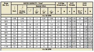
METRIC WIRE ROPES- 6 x 36 wire rope is a more flexible cable wire than 6 x 19 wire rope since it has a higher number of wires per strand. Some of the most common uses are winch lines, choker and boom lines, and works well in marine environments.
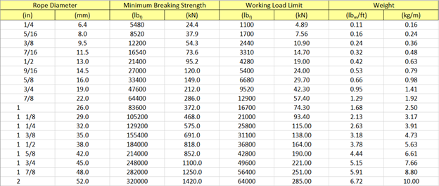
* EIPS (Extra Improved Plowed Steel) wire rope has roughly 10% more strength than regular IPS. Independent wire rope core ( IWRC ) provides added strength, reduces the amount of stretch. IWRC wire rope also is resistance to heat and provides extra corrosion resistance over a typical bright wire finish.
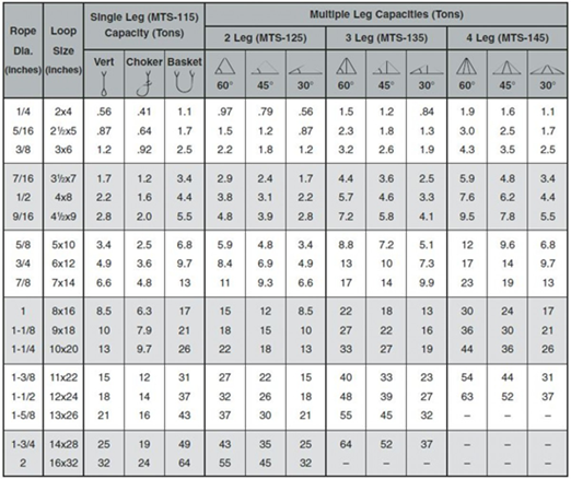
Rated load based on pin diameter no larger than one half the natural eye length or not less than the nominal sling diameter. Basket hitch capacity based on minimum D/d ratio of 25/1. For choker hitch, the angle of choke shall be 120 degrees or greater. For sling angles other than those shown, use the rated load for the next lower angle or a qualified person shall calculate the rated load. Horizontal sling angles of less than 30 degrees are not recommended. The capacity of a bridle at a 30 degree horizontal is same as single vertical leg.
SWL, NWL, MBS — all of the acronyms can get very confusing. Don’t fret – we’re here to clear things up when it comes to safe working load limits and the terms associated with it.
Safe Working Load (SWL) sometimes stated as the Normal Working Load (NWL) is the mass or force that a piece of lifting equipment, lifting device or accessory can safely utilize to lift, suspend, or lower a mass without fear of breaking. Usually marked on the equipment by the manufacturer and is often 1/5 of the Minimum Breaking Strength (MBS) although other fractions may be used such as 1/4, 1/6 and 1/10.[1][2][3]
Other synonyms include Working Load Limit (WLL), which is the maximum working load designed by the manufacturer. This load represents a force that is much less than that required to make the lifting equipment fail or yield, also known as the Minimum Breaking Load (MBL). SWL or WLL are calculated by dividing MBL by a safety factor (SF). An example of this would be a chain that has a MBL of 2000 lbf (8.89 kN) would have a SWL or WLL of 400 lbf (1.78 kN) if a safety factor of 5 (5:1, 5 to 1, or 1/5) is used.
Here at Industrial Rope Supply, we are not only committed to providing you with a quality product, but also with all the information needed to insure safety comes first on every job. Have safety questions on a product purchased from us? Contact us today and we’ll be happy to talk you through and/or provide you with the safety materials needed.
Type 304 stainless steel is the standard alloy for use in wire rope and cable. It has about the same strength as galvanized rope or cable but is much more corrosion resistant. It can be used in most industrial atmospheres and has acceptable corrosion resistance when used in marine and salt water.
Type 316 stainless steel is the standard high corrosion resistant steel for rope and cable. It is resistant to many chemicals in the pulp and paper, photographic, food processing and textile industries. It has the best pitting resistance in marine and salt water and can be used in temperatures up to 480ºC (900ºF).
The Minimum Breaking Strain is also known as the Maximum Working Load and is the stated minimum ‘strength’ of the wire rope. This load represents a mass or force that is required to make the wire rope fail or yield, also known as the Minimum Breaking Load (MBL). SWL or WLL are calculated by dividing the MBL by a safety factor (SF).
The Safe Working Load (SWL) is a common but outdated term (See “What is the Safe Working Load SWL?” post in our Advice section). The currently correct term is the Working Load Limit or WLL. SWL or WLL are calculated by dividing the MBL by a safety factor (SF) and the SF varies by application or project. Often it will be specified by the design engineer.
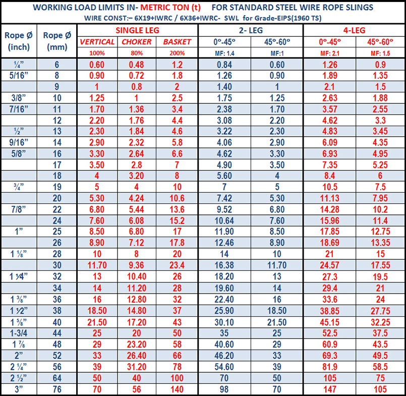
Low Cost Wire recommends a 10x SF if the lifting element (wire in this case) holds an object above ‘people’ and a 5x SF if the object is above ‘things’ and could never injure a person in the event of a catastrophic failure. The table below presents the WWL of the wire with a 10x SF when the suspended weight is held by wire in a Vertical Orientation or in a Horizontal Orientation.
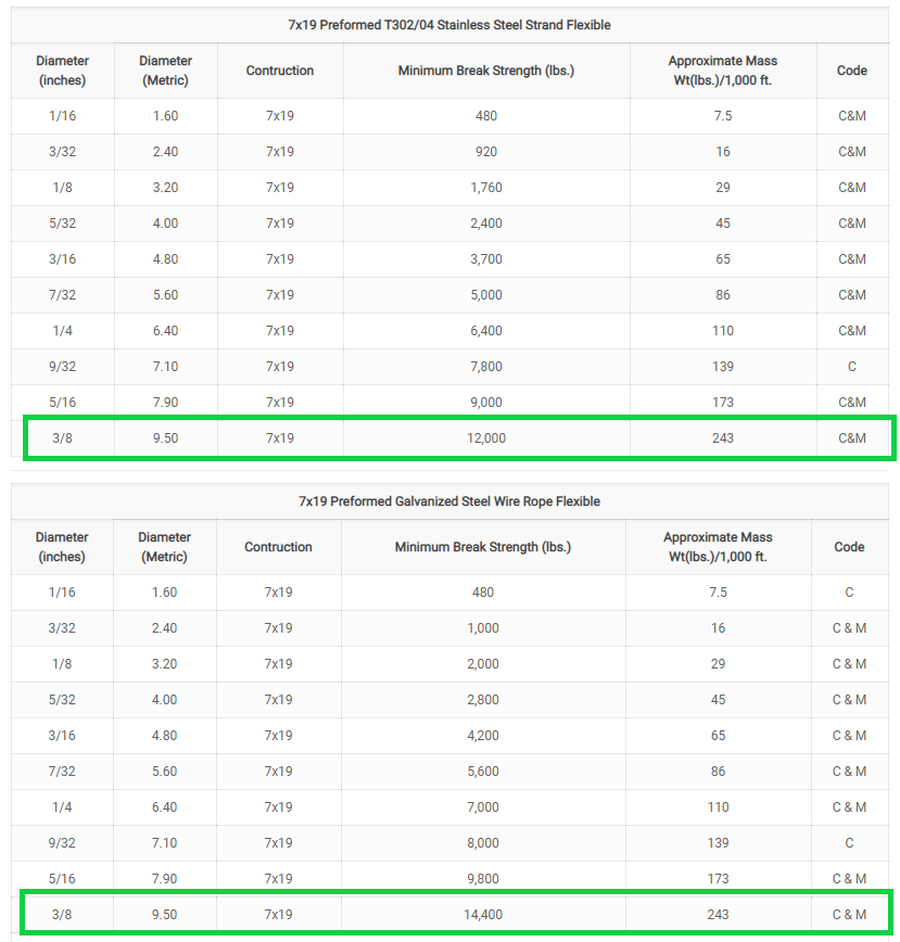
If load specification is critical, Low Cost Wire recommend that you confirm all relevant details before ordering as information may change without prior notice. Diameter Structure Grade MBS* (kN) MBS (kg)

Rope strength is a misunderstood metric. One boater will talk about tensile strength, while the other will talk about working load. Both of these are important measurements, and it’s worth learning how to measure and understand them. Each of these measurements has different uses, and here we’re going to give a brief overview of what’s what. Here’s all you need to know about rope strength.
Each type of line, natural fiber, synthetic and wire rope, have different breaking strengths and safe working loads. Natural breaking strength of manila line is the standard against which other lines are compared. Synthetic lines have been assigned “comparison factors” against which they are compared to manila line. The basic breaking strength factor for manila line is found by multiplying the square of the circumference of the line by 900 lbs.
Just being able to calculate breaking strength doesn’t give one a safety margin. The breaking strength formula was developed on the average breaking strength of a new line under laboratory conditions. Without straining the line until it parts, you don’t know if that particular piece of line was above average or below average. For more information, we have discussed the safe working load of ropes made of different materials in this article here.
It’s very important to understand the fundamental differences between the tensile strength of a rope, and a rope’s working load. Both terms refer to rope strength but they’re not the same measurement.
A rope’s tensile strength is the measure of a brand-new rope’s breaking point tested under strict laboratory-controlled conditions. These tests are done by incrementally increasing the load that a rope is expected to carry, until the rope breaks. Rather than adding weight to a line, the test is performed by wrapping the rope around two capstans that slowly turn the rope, adding increasing tension until the rope fails. This test will be repeated on numerous ropes, and an average will be taken. Note that all of these tests will use the ASTM test method D-6268.
The average number will be quoted as the rope’s tensile strength. However, a manufacturer may also test a rope’s minimum tensile strength. This number is often used instead. A rope’s minimum tensile strength is calculated in the same way, but it takes the average strength rating and reduces it by 20%.
A rope’s working load is a different measurement altogether. It’s determined by taking the tensile strength rating and dividing it accordingly, making a figure that’s more in-line with an appropriate maximum load, taking factors such as construction, weave, and rope longevity into the mix as well. A large number of variables will determine the maximum working load of a rope, including the age and condition of the rope too. It’s a complicated equation (as demonstrated above) and if math isn’t your strong point, it’s best left to professionals.
However, if you want to make an educated guess at the recommended working load of a rope, it usually falls between 15% and 25% of the line’s tensile strength rating. It’s a lotlower than you’d think. There are some exceptions, and different construction methods yield different results. For example, a Nylon rope braided with certain fibers may have a stronger working load than a rope twisted out of natural fibers.
For safety purposes, always refer to the information issued by your rope’s manufacturer, and pay close attention to the working load and don’t exceed it. Safety first! Always.
If you’re a regular sailor, climber, or arborist, or just have a keen interest in knot-tying, be warned! Every knot that you tie will reduce your rope’s overall tensile strength. Some knots aren’t particularly damaging, while others can be devastating. A good rule of thumb is to accept the fact that a tied knot will reduce your rope’s tensile strength by around 50%. That’s an extreme figure, sure, but when it comes to hauling critical loads, why take chances?
Knots are unavoidable: they’re useful, practical, and strong. Splices are the same. They both degrade a rope’s strength. They do this because a slight distortion of a rope will cause certain parts of the rope (namely the outer strands) to carry more weight than others (the inner strand). In some cases, the outer strands end up carrying all the weight while the inner strands carry none of it! This isn’t ideal, as you can imagine.
Some knots cause certain fibers to become compressed, and others stretched. When combined together, all of these issues can have a substantial effect on a rope’s ability to carry loads.
Naturally, it’s not always as drastic as strength loss of 50% or more. Some knots aren’t that damaging, some loads aren’t significant enough to cause stress, and some rope materials, such as polypropylene, Dyneema, and other modern fibers, are more resilient than others. Just keep in mind that any knots or splices will reduce your rope’s operations life span. And that’s before we talk about other factors such as the weather or your rope care regime…
In this article, we outline important technical topics related to wire rope. This information has been sourced from and approved by Bridon American. Use the outline to skip to specific sections:
Any assembly of steel wires spun into a helical formation, either as a strand or wire rope (when subjected to a tensile load) can extend in three separate phases, depending on the magnitude of the applied load.
At the commencement of loading a new rope, extension is created by the bedding down of the assembled wires with a corresponding reduction in overall diameter. This reduction in diameter is accommodated by a lengthening of the helical lay. When sufficiently large bearing areas have been generated on adjacent wires to withstand the circumferential compressive loads, this mechanically created extension ceases and the extension in Phase 2 commences. The Initial Extension of any rope cannot be accurately determined by calculation and has no elastic properties.
The practical value of this characteristic depends upon many factors, the most important being the type and construction of rope, the range of loads and the number and frequency of the cycles of operation. It is not possible to quote exact values for the various constructions of rope in use, but the following approximate values may be employed to give reasonably accurate results.
Following Phase 1, the rope extends in a manner which complies approximately with Hookes Law (stress is proportional to strain) until the limit of proportionality or elastic limit is reached.
It is important to note that wire ropes do not possess a well defined Young’s Modulus of Elasticity, but an ‘apparent’ Modulus of Elasticity can be determined between two fixed loads.
By using the values given, it is possible to make a reasonable estimate of elastic extension, but if greater accuracy is required, it is advisable to carry out a modulus test on an actual sample of the rope. As rope users will find it difficult to calculate the actual metallic steel area, the values can be found in the Wire Rope Users Manual or obtained from Bridon Engineering.
The permanent, non-elastic extension of the steel caused by tensile loads exceeding the yield point of the material. If the load exceeds the Limit of Proportionality, the rate of extension will accelerate as the load is increased until a loading is reached at which continuous extension will commence, causing the wire rope to fracture without any further increase of load.
The coefficient of linear expansion (∝) of steel wire rope is (6.94 x 10⁻⁶ per °F) and therefore the change in length of 1 foot of rope produced by a temperature change of t (°F) would be:
Example: What will be the total elongation of a 200 ft. length of 1-1/8″ diameter Blue Strand 6 x 41 IWRC wire rope at a tension of 20,000 Ibs. and with an increase in temperature of 20°F?
In addition to bending stresses experienced by wire ropes operating over sheaves or pulleys, ropes are also subjected to radial pressure as they make contact with the sheave. This pressure sets up shearing stresses in the wires, distorts the rope’s structure and affects the rate of wear of the sheave grooves. When a rope passes over a sheave, the load on the sheave bearing results from the tension in the rope and the angle of rope contact. It is independent of the diameter of the sheave.
Assuming that the rope is supported in a well fitting groove, then the pressure between the rope and the groove is dependent upon the rope tension and diameter, but is independent of the arc of contact.
It must be realized that this method of estimation of pressure assumes that the area of contact of the rope in the groove is on the full rope diameter, whereas in fact only the crowns of the outer wires are actually in contact with the groove. It is estimated that the local pressures at these contact points may be as high as five times those calculated. If the pressure is high, the compressive strength of the material in the groove may be insufficient to prevent excessive wear and indentation, and this in turn will damage the outer wires of the rope and effect its working life.
As with bending stresses, stresses due to radial pressure increase as the diameter of the sheave decreases. Although high bending stresses generally call for the use of flexible rope constructions having relatively small diameter outer wires, these have less ability to withstand heavy pressures than do the larger wires in the less flexible constructions. If the calculated pressures are too high for the particular material chosen for the sheaves or drums or indentations are being experienced, consideration should be given to an increase in sheave or drum diameter. Such a modification would not only reduce the groove pressure, but would also improve the fatigue life of the rope.
The pressure of the rope against the sheave also causes distortion and flattening of the rope structure. This can be controlled by using sheaves with the correct groove profile, which, for general purposes, suggests a recommended groove diameter of nominal rope diameter +6%. The profile at the bottom of the groove should be circular over an angle of approximately 120° and the angle of flare between the sides of the sheave should be approximately 52°.
Bend fatigue testing of ropes usually consists of cycling a length of rope over a sheave while the rope is under a constant tension. As part of their ongoing development program, Bridon has tested literally thousands of ropes in this manner over the years on their own in-house design bend testing equipment.
Through this work, Bridon has been able to compare the effects of rope construction, tensile strength, lay direction, sheave size, groove profile and tensile loading on bend fatigue performance under ideal operating conditions. At the same time it has been possible to compare rope life to discard criteria (e.g. as laid down in ISO 4309) with that to complete failure of the rope, i.e. to the point where the rope has been unable to sustain the load any longer. As part of the exercise, it has also been possible to establish the residual breaking strength of the rope at discard level of deterioration.
What needs to be recognized, however, is that very few ropes operate under these controlled operating conditions, making it very difficult to use this base information when attempting to predict rope life under other conditions. Other influencing factors, such as dynamic loading, differential loads in the cycle, fleet angle, reeving arrangement, type of spooling on the drum, change in rope direction, sheave alignment, sheave size and groove profile, can have an equally dramatic effect on rope performance.
If designers or operators of equipment are seeking optimum rope performance or regard bending fatigue life as a key factor in the operation of equipment, such information can be provided by Bridon for guidance purposes.
Wire ropes are manufactured slightly larger than the nominal diameter. The maximum allowable oversize tolerances provided by industry standards are shown in the following table:
Under certain circumstances it may be necessary to use a swivel in a lifting system to prevent rotation of the load. This is typically done for employee safety considerations. It is possible however, that the use of a swivel will have an adverse affect on rope performance and may, in some cases, damage the wire rope.
The type of swivel that causes the most concern from the standpoint of the wire rope is the independent anti-friction swivel that attaches directly to the rope. The purpose of using a swivel in a lifting system is to prevent rotation of the load. This then allows the wire rope to rotate. Excessive rope rotation can damage a wire rope.
To assist in determining whether or not a swivel should be used in the lifting system, the following recommendations should be considered. It must also be recognized that the rotation characteristics of different types and constructions of wire rope vary considerably. The following types and constructions of wire rope are grouped according to their rotation characteristics.
These rope constructions will rotate excessively with one end free to rotate, and the rope will unlay and distort and be easily damaged with a loss of rope breaking force.Blue Strand 6 x 19 and 6 x 36 Class Lang Lay
Wire rope constructions having high rotation characteristics when used in single part reeving may require a swivel in the system to prevent rotation in certain operating conditions. However, this should be done only when employee safety is the issue.
These rope constructions, when used in a reeving system with one end free to rotate, will have a high level of rotation. This will cause the rope to unlay and, to some degree, distortion of the rope will occur.Blue Strand 6 x 19 and 6 x 36—Class Regular Lay
The ropes in this Group are designed with an inner rope that is laid in the opposite direction to the outer strands to provide a medium resistance to rotation. Ropes with medium rotation characteristics are used with a swivel in single part reeving applications. However, a swivel is not recommended for multiple part hoisting applications or in any application where the swivel is not necessary for safety reasons. If it is necessary to use a swivel, the rope must be operating at a design factor of 5 or greater, must not be shock loaded and must be inspected daily by a qualified person for distortion.
It should be noted that if a swivel is used on conjunction with Group 3a ropes, rope service life might be reduced due to increased internal wear between the outer strands and the inner rope.Group 3aEndurance 8RR Rotation Resistant
Wire ropes having low rotation characteristics used in either single or multiple part reeving may be used with a swivel. The reason for this is that the ropes will exhibit very little, if any, rotation when used at the proper design factor. Application parameters, such as a fleet angle, may induce turn into a wire rope that can be relieved by the use of a swivel. However, if the application does not induce any turn into the rope, or if a swivel is not beneficial to the performance of the rope, the swivel may not be necessary.Endurance 35 LS
If the drum incorporates helical grooving, the helix angle of the groove needs to be added or subtracted from the fleet angle as described above to determine the actual fleet angle experienced by the rope.
When spooling rope onto a drum, it is generally recommended that the fleet angle is limited to between 0.5° and 2.5°. If the fleet angle is too small, i.e. less than 0.5°, the rope will tend to pile up at the drum flange and fail to return across the drum. In this situation, the problem may be alleviated by introducing a ‘kicker’ device or by increasing the fleet angle through the introduction of a sheave or spooling mechanism.
If the rope is allowed to pile up, it will eventually roll away from the flange, creating a shock load in both the rope and the structure of the mechanism, an undesirable and unsafe operating condition.
Excessively high fleet angles will return the rope across the drum prematurely, creating gaps between wraps of rope close to the flanges, as well as increasing the pressure on the rope at the cross-over positions.
Even where helical grooving is provided, large fleet angles will inevitably result in localized areas of mechanical damage as the wires ‘pluck’ against each other. This is often referred to as ‘interference’, but the amount can be reduced by selecting a Langs lay rope if the reeving allows. The “interference” effect can also be reduced by employing a Dyform rope, which offers a much smoother exterior surface than conventional rope constructions.
Where a fleet angle exists as the rope enters a sheave, it initially makes contact with the sheave flange. As the rope continues to pass through the sheave it moves down the flange until it sits in the bottom of the groove. In doing so, even when under tension, the rope will actually roll, as well as slide. As a result of the rolling action, the rope is twisted, i.e. turn is induced into or out of the rope, either shortening or lengthening the lay length of the outer layer of strands. As the fleet angle increases, so does the amount of twist.
To reduce the amount of twist to an acceptable level, the fleet angle should be limited to 2.5° for grooved drums and 1.5° for plain drums and when using Rotation Resistant, ropes the fleet angle should be limited to 1.5°.
However, for some crane and hoist applications, it is recognized that for practical reasons. It is not always possible to comply with these general recommendations, in which case, the rope life could be affected.
The problem of torsional instability in crane hoist ropes would not exist if the ropes could be perfectly torque balanced under load. The torque generated in a wire rope under load is usually directly related to the applied load by a constant ‘torque factor’. For a given rope construction, the torque factor can be expressed as a proportion of the rope diameter and this has been done below.
Variation with rope construction is relatively small and hence the scope for dramatically changing the stability of a hoisting system is limited. Nevertheless, the choice of the correct rope can have a deciding influence, especially in systems which are operating close to the critical limit. It should be noted that the rope torque referred to here is purely that due to tensile loading. No account is taken of the possible residual torque due, for example, to rope manufacture or installation procedures.
Torsional Stability and the Cabling Graph are two methods which can be used to determine torsional stability or the tendency of the rope to cable. The torque factors quoted are approximate maximum values for the particular constructions. To calculate the torque value for a particular rope size, multiply by the nominal rope diameter.
The torsional characteristics of wire rope will have the effect of causing angular displacement of a sheave block when used in multi-fall reeving arrangements. The formula below gives a good approximation under such arrangements.
The preceding equations are all relative to a simple two part reeving. For more complex systems, a similar approach may be used if account is taken of the different spacings of the ropes.
The equations assume that rope is torque-free in the noload condition, therefore, induced torque during or immediately after installation will adversely influence the calculated effect.
The above data assumes a constant torque value which is a valid assumption for a new rope. Wear and usage can have a significant effect on the torque value, but practical work shows that under such circumstances, the torque value will diminish, thus improving the stability of the arrangement. Some arrangements may be of such complexity that the evaluation demands a computer study.
Assuming a pedestal crane working on two falls is roped with 20mm diameter DYFORM 34LR and the bottom block carries a sheave of 360mm diameter with the falls parallel:
If the rope is new (worst condition) and no account is taken of block weight and friction then angular displacement for a height of lift of 30 meters is given by:
Field research jointly conducted by the Wire Rope Technical Board and the Power Crane and Shovel Association has shown that cabling of the rope parts in a multiple part reeved hoisting arrangement is controlled by several factors. The following calculations and graphs can be used to determine when and if cabling will occur on multiple part reeved hoisting arrangements.
Various constructions of rope shown on the graph indicate the limited conditions for torsional stability with the angular displacement of the hoist block to a maximum of 90 degrees. When the operating conditions for a particular installation give a resultant above the appropriate band, then cabling of the falls will most likely occur. If the operating conditions give a resultant below any particular band, the cabling of the falls will most likely not occur. If the operating conditions for any particular installation fall within the band, cabling is unpredictable.

MATERIAL: Steel grades in wide use today are IPS (improved plow steel), EIPS (extra improved plow steel), sometimes also referred to as XIPS, XIP, or EIP, as well as EEIPS (extra, extra improved plow steel).
CONSTRUCTION: Expressed in numbers of strands x number of wires. 6 x 25 indicates that the wire rope consists of 6 strands, which in turn have 25 individual wires.
How to measure (or caliper) a wire rope correctly. Since the "true" diameter (A) lies within the circumscribed circle, always measure the larger dimension (B). Actual diameter can be 5% larger than nominal wire rope diameter.
There are numerous ways to cut wire rope - use only appropriate tools specifically designed to cut wire rope. Safety goggles and work gloves must always be worn. Observe other precautions peculiar to the tools used. Wire rope should be properly seized on both sides of the cut with wire or strand. Seizing wire diameter and the number and length of the seizings will depend on the diameter of the wire rope, and whether or not it is preformed.
Since wire rope is a machine with many moving parts, it requires careful installation and breaking in procedures for maximum safety and long service life. After proper installation, allow the wire rope to run through a cycle of operation at a very low speed. Keep a close watch on the wire rope, its attachments and any working parts such as sheaves, drums, rollers, etc. to make certain that the wire rope runs freely. If no problems appear at this stage, run the wire rope through several cycles of operation under light load at reduced speed. This procedure allows the component parts of the new rope to make a gradual adjustment to the actual operating conditions.
Wire rope will develop 100% efficiency, that is, break at or above minimum acceptance strength (not less than 2 1/2% below nominal breaking strength) under controlled laboratory conditions. Once fittings such as sleeves, clips, sockets, etc. are attached and/or the wire rope passes over a curved surface such as sheaves, pins, etc. its strength is decreased. In the case of wire rope passing over a curved surface this decrease in strength depends on the severity of the bend. In the case of wire rope fittings, the decrease in wire rope strength will depend on the type of fittings used. The wire rope efficiency usually ranges from 70% - 100%. For more detailed information consult the strength efficiency of wire rope table on page 86. Note, that hand spliced wire rope, while not using any fittings, has less efficiency than properly flemished and swaged wire rope. There are other factors, depending on the application of wire rope, that can cause a decrease in nominal wire rope strength. They must be considered when choosing a design factor. Refer to the Wire Rope Users Manual and/or other qualified sources for details.
Wire rope is an elastic member; it stretches or elongates under load. This elongation can be permanent or recoverable. The extent of elongation will depend on the wire rope used and the design factor chosen. While it may be acceptable for many wire rope uses to neglect its elastic properties, they are of critical importance for some uses. When in doubt about the importance of wire rope elongation consult professional help. Pre-stretching wire rope will only remove some of the constructional stretch and will not totally eliminate elongation under load.
Installation of wire rope on a plain or grooved drum requires a great deal of care. Make certain the wire rope is properly attached to the drum. Keep adequate tension on the wire rope as it is wound onto the drum. Guide each wrap as close to the preceding wrap as possible, or follow the groove in case of a grooved drum. No blanket recommendations can be given concerning direction of winding, desirable drum diameter, fleet angle, etc. Consult the Wire Rope Users Manual for this and other important technical information.
Stainless steel wire ropes are more than just elegant; they are also an ideal alternative over traditional materials limited in functionality and style. When using stainless steel wire ropes, you get a wide range of options and benefits. Using stainless steel offers an amazing advantage to the ornamental and architectural industry. This material"s main benefits include high corrosion resistance that allows the material to function and survive harsh environmental conditions. Stainless steel wires are also great at resisting heat and fire, which helps them to resist scaling while also retaining strength during high temperatures.
Stainless steel wire rope is commonly used because it offers both horizontal and vertical choices. Horizontal rope railings are highly specific. On the other hand, vertical wire ropes offer a more attractive alternative that is great for architecture. These ropes have a clean and minimalist appearance when compared to horizontal ropes.
If your application needs sensitivity to corrosion (water, weather, salt, etc.), stainless steel cables could be your best choice. The material is known for its strong work in harsh environmental conditions. Cables can take a beating and still be reliable. A galvanized stainless steel wire rope is vulnerable to corrosion, and as such, it should not be used under these conditions. When working in marine settings, stainless steel wire ropes and nylon slings should be your first choice.


 8613371530291