
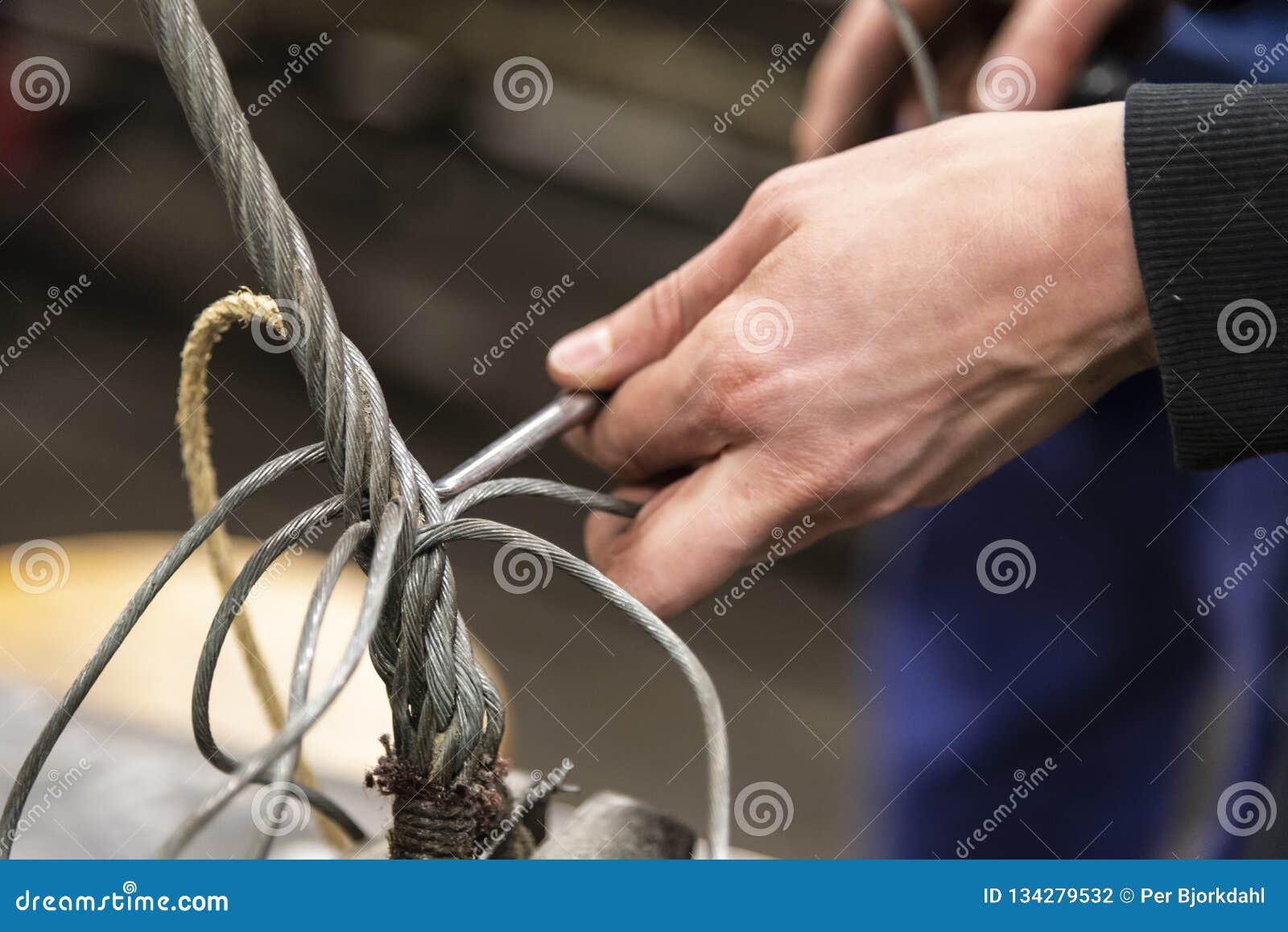
steel wire rope splicing free sample

Premiumropes has developed an App “RopeSplicing". This App contains tutorials for more than 30 rope splices. With over a 1,000 detailed and zoomable pictures the App takes you step-by-step through the splicing process.
The App is the idea of Jan- Willem Polman, founder of Premiumropes. “Everybody can learn how to splice modern ropes. Having a clear set of instructions and good example pictures is important. This App provides you with just that ! There are over 1100 pictures in the App to guide you through every step. Most pictures are self explanatory and with some pictures clear and short text instructions are provided."
The App is fully usable offline. Polman: “Almost every marina in the world has Wi-Fi. But it’s not always free. Besides you are not always in the marina with your boat. This is why we wanted the Ropesplicing App to be usable offline. This way you can use the App even in the most remote places."
By following the clear step-by-step photographs you learn how to splice ropes, make shackles and customize ropes to make your boat set-up easier, lighter and safer. Both sailors and arborists will find this a very complete and useful rope splicing app.

Alibaba.com offers a classic collection of steel wire rope splicing machine machines that are powerful, sturdy, and loaded with unique sets of features for more enhanced performances. These modernized machines can contribute to all types of heavy-duty lathe requirements involving metal, leather, etc. These technically-advanced steel wire rope splicing machine are equipped with a broad spectrum of fascinating features that offer superior precision and consistent performance level. Leading steel wire rope splicing machine suppliers and wholesalers on the site offer these premium machines for competitive prices and intriguing deals.
The incredibly powerful steel wire rope splicing machine are not only made up of sturdy materials such as metal and FRP but also very sustainable against all kinds of usages. These machines are ideal for use in the manufacturing industry due to the wide variety of purposes that they cater to. The steel wire rope splicing machine on the site are available in both semi-automatic and automatic versions depending on your requirements. Coming with distinct capacities and max spindle speeds, these steel wire rope splicing machine are well efficient in processing distinct workpieces such as shafts, discs, and rings.
Alibaba.com boasts of multiple steel wire rope splicing machine available in various designs, shapes, colors, and sizes depending on your specific requirements and the models are chosen. These superior-quality steel wire rope splicing machine are ideally used for distinct purposes such as drilling, reaming, tapping, and knurling in accordance with your preferences. The products available here are provided with a centralized automatic lubrication guide to reduce heat distortion and offers better stability. These steel wire rope splicing machine are also equipped with low noise generating technology for soundless performance.
At Alibaba.com, you get to select among distinct steel wire rope splicing machine depending on your specific budget and requirements to purchase these products without having to spend excessive money. These products are ISO, CE certified and are available as OEM orders. Customizing is also an option when you are buying these machines in bulk.

The present invention is related to splicing or wire ropes or cables, particularly for those used for uphill and overhead transportation systems and the like wherein strength and smoothness and an assured rope life are essential to safe and reliable operation of such systems.
With increasing traffic and use of uphill and overhead transportation systems such as ski lifts, amusement park skyrides and tour sightseeing rides, the need for safe, reliable and minimum maintenance of the wire rope and cabling which transmit the power as well as actually effecting the transport of passengers has become all the more important. Moreover, provision of strong splices, long life and smooth rides are of extreme importance in such transportation systems. The wire rope cables frequently convey passengers over the most rugged of terrains and replacement of cables is accordingly difficult, dangerous and desirably kept to a minimum.
The wire rope splice which constantly passes over the support sheaves of such systems, thus should conform uniformly over its length to the diameter of the main body and should be without bulges or recesses in the wire rope surface. The rope system is otherwise likely subject to vibrations and jerks in passage between towers and over numerous sheaves and about drive and take-up wheels during operation with consequent unnecessary shock stressing of the rope and shortening of the life of the wire rope, particularly in the splice region.
In view of the foregoing, it is an object of the present invention to provide a wire rope splice assembly and components which will enable provision of a strong connection of ends in conformity with the diameter of the main body of the rope to impart a smoothness in operation and to promote a longer rope life.
Another object of the invention is to provide a stable splice arrangement for wire ropes and cables having minimum or no recesses, indentations or bulges in the exposed rope surface.
Still another object of the invention is to provide a strong wire rope splice assembly wherein positive inter-engagement of the outer and inner strands in the splice region is promoted under loading.
Another and still further object of the invention is to provide a splice for wire ropes wherein weakness or damage due to abrasion between strands and the core as well as strand portions located in the core region are reduced to increase the life of such ropes in use.
In the prior art, where the usual wire rope has six strands helically laid about a core, it is well known to form a splice over a long length of the rope by pairing up oppositely extending ends of equal lengths of the rope and tucking three strands of each into spaced apart core regions of the other. Portions of the core of each end are removed for lengths correspondingly generally to the length of the strand end portions to be tucked therein. The outer strand portions to be tucked into the core region of the splice are covered or wound with cotton, duct, twine or friction tape to protect the strands against inter-abrasion in the tuck regions. Such protective materials, although providing a degree of protection and increased life, are particularly vulnerable to wear, breakdown and deterioration, not only because of stresses of heavy loading and working as by flexing and twisting and abrasion in use, but also because of the extreme weather and other environmental conditions to which such ropes and cables are frequently subjected.
The splice in a wire rope or cable is usually the poorest portion since any distortion in the region causes a greater working of the material in the splice region than the remainder of the rope thereby promoting a progressive weakening of the splice. According to the present invention where long splices are made such as by tucking a length of each strand end individually into the core region of the wire rope, each such strand end is enclosed in a continuous tubular sheath to fill the space left by removal of the core and to protect the strands in the tuck region against wear.
The center of core region of a wire rope is usually a little larger than the diameter of the outer strand and voids are presented when an outer strand is inserted in the core region. Where the wire rope is the usual steel rope, a protective and filling sheath about the tucked portion of steel strand is desirably of bearing type material such as copper, aluminum, lead and alloys thereof or synthetic resin material such as nylon which will be compatible in wear resistance which although not fully understood is believed to be provided by a cushioning action which reduces scarfing and frictional abrasion between the center and outer steel strands. Also when such tubing is placed around the strand in the core region, lubrication materials in the strand are locked in which not only assures prolonged lubrication but reduces the possibilities of dry rust from forming.
The metal of the strand enclosing sheath is preferably made different in hardness from that of the wire rope. It is well known that dissimilar materials such as steel and bronze are more compatible in frictional relation, as in a bearing than one material against itself such as steel on steel in frictional engagement. This combination of a hard surface metal and a contacting softer bearing type material surface results in an excellent bearing interface combination and this property is embodied in the present invention to reduce the effects of abrasion in the splice region.
Another aspect of the invention is that where a void is formed such as at each point of crossover or intersection between two strands tucked into the core region of the wire rope, a filler member is provided to back up the strand portions in the region to contribute to conformity of the strands to the exterior dimension and shape of the rope at each of the splice intersections. The filler and back-up member it is found lessens distortion of the strands in the crossover regions and promotes longer life of the wire rope in the spliced region. Like the sheath member, the filler member may be of metal such as copper, aluminum, lead or alloys thereof or resinous material such as nylon which will act compatibly to reduce results from abrasion with steel strands of the rope.
FIG. 1 is a general overall view of a portion of an uphill wire rope or cable transportation system such as a ski lift in which the protective splice members and splice assembly of the present invention may be advantageously utilized;
FIG. 2 shows two ends of a wire rope to be spliced with a "V" designating each of the regions along the length of the main body of the rope at which a strand of one end is to be crossed with a corresponding strand of the other end tucked into the core region of the other end of the rope;
FIG. 4 is a schematic layout of the strand and core arrangement of the spliced rope of FIG. 3 illustrating the location of protective sheaths over each tucked strand end and intermediate core sections of the rope;
FIG. 5 is an enlarged view of a strand crossover region of the spliced cable with two strands of the rope deleted to illustrate more clearly the location of the protective strand sheaths of the invention;
FIG. 6 is a slightly longer view of the crossover region of FIG. 5 with deleted strands shown in dotted lines and showing the manner in which the sheathed strand portion is aligned with and extends to the core portion of the rope;
FIG. 7 is a view of a strand crossover region of a rope splice as illustrated in FIGS. 2-6 showing a protective filler and back-up member of the present invention located in and conforming in general shape to the space formed in the strand crossover region; and
Referring to the drawings in greater detail, FIG. 1 illustrates a ski lift representative of an uphill transportation system wherein a spliced cable or wire rope is passed over a series of sheaves for uphill conveyance of passengers. A rope support 11 extending laterally from a tower 10 incorporates a series of sheaves 12 over which a wire rope 25 passes. A series of chairs, represented by a double chair 14 are each supported from its respective bar 16 secured to and hanging from the wire rope 25. The longer the upward incline, the greater the number of sheaves the wire rope is required to pass over and correspondingly the greater the loading and working on the wire rope in conveying passengers uphill. Strength and uniformity of the splice in the wire rope accordingly is all the more important to long life and safety of the entire system.
The ski lift of FIG. 1 is representative of a number of uphill and overhead transportation systems utilizing wire ropes and cables in which the protective splice members and splice assembly of the present invention may be particularly advantageously utilized. Chairlifts, T-bar lifts, sky rides tramways and other transportation systems utilizing wire ropes or cables for power transmission and passenger conveyance are all of a type in which safety is of extreme importance as imparted by the structural features of the present invention.
FIG. 2 illustrates the manner in which a long splice can be made of two ends 26 and 27 of the wire rope 25 in which the protective components of the present invention lend themselves particularly to imparting safety and a longer life of such a splice assembly. The opposite ends 26 and 27 of the wire rope are first unwound and the fibrous core sections are removed therefrom. Commercial wire ropes usually have six strands distributed helically about a core of metal or of fiber. The point M at which the two ends 26 and 27 are unwound to free the strands for subsequent weaving into a splice is termed the marriage point. Three of the strands of each end are cut back to predetermined points beyond the marriage point leaving three free strand ends to be mated with corresponding strands at the spaced tuck positions a, b, c and d, e and f of wire rope 25. In tucking an end portion of a strand into the core region of the wire rope, a dagger tool is used to form an opening between strands. A tucker tool is placed in the opening between the strands and the fiber core is removed with a pair of pliers as the tucking progresses. The corresponding strands of the opposite ends of the rope are mated in each of these tuck positions by being crossed over and inserted in the core space of the other end of the rope.
FIG. 3 illustrates the spliced rope 25 and the tuck positions or regions a, b and c on one side of the marriage point M and positions d, e and f on the other in which crossovers of corresponding pairs of strands are effected and tucked into the core space of the rope.
FIG. 4 illustrates in plan view the arrangement of the corresponding strand ends in each of the tuck regions of FIG. 3 and illustrates how the strand layout pattern would appear if the helically oriented strands in the splice region were unwound and laid out flat on either side of the core strand 30 of the rope. The oppositely tucked ends of corresponding strands of the two ends are shown more clearly in the tuck regions a, b, c, d, e and f of the long splice with portions of the original core 30 remaining in between the tuck regions as shown at 30a, 30b, 30c, 30d and 30e respectively. Three of the tuck regions are on one side of the marriage point M and three on the other side.
According to the present invention each end of the pair of strand ends in the six tuck regions is covered with a metal tubing. Each tube encompasses a strand end for substantially its full length in the tuck region. Copper tubing has been found to function admirably in protecting tucked strands of spliced steel wire ropes and as shown in FIG. 5 the tubing is provided with a slit along its full length to permit it to be opened such as with pliers and then clamped in surrounding relation about the strand end.
FIG. 5 illustrates the crossover and tuck region of the splice with two of the six strands of the rope removed. Strands 51 and 52 are crossed and their ends are enclosed in copper tubes 56 and 57 respectively. The tubing 56, as illustrated more clearly in FIG. 6, is arranged to be the same diameter as the core 60, portions of which were removed to make space for insertion of the strand 51 with the enclosed copper tubing 56 therein. The copper tubing is slit such as with a saw and is then opened and clamped about the strand 56 and inserted in the core region in alignment with the original core of the wire rope. The wall thickness of the tubing is selected to fill the space left after removal of the core, but not so thick as to cause the outer strands to bulge nor the tucked ends to be excessively stiff. For example, for a 11/2 inches diameter wire rope, strands have a diameter of approximately 3/8 inch and a copper tubing having an OD of 1/2 inch may be used. The wall thickness of commercial tubing of this size is usually 3/64 inch.
The gap 59 of the tubing 56 is made to be sufficiently wide that after being clamped around the strand, the confronting edges of the tube do not contact each other and are sufficiently far apart that after a period of use of the wire rope in which it is inserted, the tube can close still tighter about the strand under the lateral forces applied thereto by the outer strands upon application of tension forces to the wire rope. After initial clamping of the tubing about the strand, however, the gap 59 is preferably not so wide that wire filaments of the strand can pass therethrough, and in this regard, the gap is usually preferred not to be greater in width in its clamped condition than the diameter of a filament of the strand portion which it holds enclosed.
Where a wire rope provided with a splice of the type illustrated is placed in tension, such as in an uphill lift, the tension causes the outer strand to bear tighter against the surfaces of the interior tubing surrounding the strand portions in the tucked region. Accordingly after a period of use, the surface of the tubing can become indented slightly in conformation with the filaments bearing against the tube, thereby establishing a better grip between the outer strand with the portion of strand in the tuck region, both causing a more positive mechanical engagement therewith and tighter clamping of the tubing about the portion of the strand which it encloses. Since the friction of the tucked strands is the holding strength of the splice, metal sheaths covering the tucked strand lengths serve to add tensile resistance to the splice, thus not only adding strength but more deterioration resistant life to the splice.
FIG. 7 shows another aspect of the invention wherein a backup member 70, such as of metal like copper, is inserted in the void in the splice region below the crossover of two strands 61 and 62 of the wire rope. At the point of intersection of the two strands tucked on the inside of the wire rope there is a void space. A length of solid metal rod or a rod of resinous material like nylon having oppositely inclined ends and corresponding generally to the length of the void is inserted in the void to fill the space. This filler and backup member is shown in FIG. 7 in a somewhat extended sense to illustrate more clearly how it functions. Member 70 contributes to the conformity of the wires to the diameter of the rope at the strand intersections of the splice. The addition of this filler member results in much less distortion and longer wire rope life in the spliced region in comparison to splice assemblies where the void space is allowed to remain unfilled.
FIG. 8 illustrates the combination filler and backup member 70 in perspective showing the beveled or inclined ends 71 and 72 illustrating more clearly that it can be ciruclar and is made to conform generally to the space under the crossing rope strands 61 and 62 in alignment with the core space including the tubing 66 surrounding the strand in the tuck region.
The length of the filler backup member may be approximately half the length of lay of strand in the helical configuration of the wire rope. For example, if the lay is approximately 71/2 inches, the length of the backup member may be about 3 inches to fill in the voids below the crossover space of the tuck position. Still further, the member 70 for a 11/8 inches diameter rope may be 3 inches long and have a diameter of 3/8 inch which matches generally that of the strands in the wire rope. Although member 70 is herein shown as being in the crossover region in alignment with the strand section surrounded with protective tubing 66, it will be recognized that it may also be utilized advantageously in splice arrangements without the use of the protective tubing about the tucked in strand portions. After a period of use of a spliced cable, the backup member 70, like the tubing 10, also is locked in place more tightly within the core space of the crossover region. This in turn causes a more positive holding of the strand portions in the core regions after a period of use of the spliced wire rope.

Wire rope forms an important part of many machines and structures. It is comprised of continuous wire strands wound around a central core. There are many kinds of wire rope designed for different applications. Most of them are steel wires made into strands wound with each other. The core can be made of steel, rope or even plastics.
Wire ropes (cables) are identified by several parameters including size, grade of steel used, whether or not it is preformed, by its lay, the number of strands and the number of wires in each strand.
A typical strand and wire designation is 6x19. This denotes a rope made up of six strands with 19 wires in each strand. Different strand sizes and arrangements allow for varying degrees of rope flexibility and resistance to crushing and abrasion. Small wires are better suited to being bent sharply over small sheaves (pulleys). Large outer wires are preferred when the cable will be rubbed or dragged through abrasives.
There are three types of cores. An independent wire rope core (IWRC) is normally a 6x7 wire rope with a 1x7 wire strand core resulting in a 7x7 wire rope. IWRCs have a higher tensile and bending breaking strength than a fiber core rope and a high resistance to crushing and deformation.
A wire strand core (WSC) rope has a single wire strand as its core instead of a multistrand wire rope core. WSC ropes are high strength and are mostly used as static or standing ropes.
Wire ropes also have fiber cores. Fiber core ropes were traditionally made with sisal rope, but may also use plastic materials. The fiber core ropes have less strength than steel core ropes. Fiber core ropes are quite flexible and are used in many overhead crane applications.
The lay of a wire rope is the direction that the wire strands and the strands in the cable twist. There are four common lays: right lay, left lay, regular lay and lang lay. In a right lay rope the strands twist to the right as it winds away from the observer. A left lay twists to the left. A regular lay rope has the wires in the strands twisted in the opposite direction from the strands of the cable. In a lang lay rope, the twist of the strands and the wires in the strands are both twisted the same way. Lang lay ropes are said to have better fatigue resistance due to the flatter exposure of the wires.
Wire ropes are made mostly from high carbon steel for strength, versatility, resilience and availability and for cost consideration. Wire ropes can be uncoated or galvanized. Several grades of steel are used and are described in Table 1.
Steel cable wire is stiff and springy. In nonpreformed rope construction, broken or cut wires will straighten and stick out of the rope as a burr, posing a safety hazard. A preformed cable is made of wires that are shaped so that they lie naturally in their position in the strand, preventing the wires from protruding and potentially causing injury. Preformed wire ropes also have better fatigue resistance than nonpreformed ropes and are ideal for working over small sheaves and around sharp angles.
Lubricating wire ropes is a difficult proposition, regardless of the construction and composition. Ropes with fiber cores are somewhat easier to lubricate than those made exclusively from steel materials. For this reason, it is important to carefully consider the issue of field relubrication when selecting rope for an application.
There are two types of wire rope lubricants, penetrating and coating. Penetrating lubricants contain a petroleum solvent that carries the lubricant into the core of the wire rope then evaporates, leaving behind a heavy lubricating film to protect and lubricate each strand (Figure 2). Coating lubricants penetrate slightly, sealing the outside of the cable from moisture and reducing wear and fretting corrosion from contact with external bodies.
Both types of wire rope lubricants are used. But because most wire ropes fail from the inside, it is important to make sure that the center core receives sufficient lubricant. A combination approach in which a penetrating lubricant is used to saturate the core, followed with a coating to seal and protect the outer surface, is recommended. Wire rope lubricants can be petrolatum, asphaltic, grease, petroleum oils or vegetable oil-based (Figure 3).
Petrolatum compounds, with the proper additives, provide excellent corrosion and water resistance. In addition, petrolatum compounds are translucent, allowing the technician to perform visible inspection. Petrolatum lubricants can drip off at higher temperatures but maintain their consistency well under cold temperature conditions.
Various types of greases are used for wire rope lubrication. These are the coating types that penetrate partially but usually do not saturate the rope core. Common grease thickeners include sodium, lithium, lithium complex and aluminum complex soaps. Greases used for this application generally have a soft semifluid consistency. They coat and achieve partial penetration if applied with pressure lubricators.
Petroleum and vegetable oils penetrate best and are the easiest to apply because proper additive design of these penetrating types gives them excellent wear and corrosion resistance. The fluid property of oil type lubricants helps to wash the rope to remove abrasive external contaminants.
Wire ropes are lubricated during the manufacturing process. If the rope has a fiber core center, the fiber will be lubricated with a mineral oil or petrolatum type lubricant. The core will absorb the lubricant and function as a reservoir for prolonged lubrication while in service.
If the rope has a steel core, the lubricant (both oil and grease type) is pumped in a stream just ahead of the die that twists the wires into a strand. This allows complete coverage of all wires.
After the cable is put into service, relubrication is required due to loss of the original lubricant from loading, bending and stretching of the cable. The fiber core cables dry out over time due to heat from evaporation, and often absorb moisture. Field relubrication is necessary to minimize corrosion, protect and preserve the rope core and wires, and thus extend the service life of the wire rope.
If a cable is dirty or has accumulated layers of hardened lubricant or other contaminants, it must be cleaned with a wire brush and petroleum solvent, compressed air or steam cleaner before relubrication. The wire rope must then be dried and lubricated immediately to prevent rusting. Field lubricants can be applied by spray, brush, dip, drip or pressure boot. Lubricants are best applied at a drum or sheave where the rope strands have a tendency to separate slightly due to bending to facilitate maximum penetration to the core. If a pressure boot application is used, the lubricant is applied to the rope under slight tension in a straight condition. Excessive lubricant application should be avoided to prevent safety hazards.
Some key performance attributes to look for in a wire rope lubricant are wear resistance and corrosion prevention. Some useful performance benchmarks include high four-ball EP test values, such as a weld point (ASTM D2783) of above 350 kg and a load wear index of above 50. For corrosion protection, look for wire rope lubricants with salt spray (ASTM B117) resistance values above 60 hours and humidity cabinet (ASTM D1748) values of more than 60 days. Most manufacturers provide this type of data on product data sheets.
Cable life cycle and performance are influenced by several factors, including type of operation, care and environment. Cables can be damaged by worn sheaves, improper winding and splicing practices, and improper storage. High stress loading, shock loading, jerking heavy loads or rapid acceleration or deceleration (speed of the cable stopping and starting) will accelerate the wear rate.
Corrosion can cause shortened rope life due to metal loss, pitting and stress risers from pitting. If a machine is to be shut down for an extended period, the cables should be removed, cleaned, lubricated and properly stored. In service, corrosion and oxidation are caused by fumes, acids, salt brines, sulfur, gases, salt air, humidity and are accelerated by elevated temperatures. Proper and adequate lubricant application in the field can reduce corrosive attack of the cable.
Abrasive wear occurs on the inside and outside of wire ropes. Individual strands inside the rope move and rub against one another during normal operation, creating internal two-body abrasive wear. The outside of the cable accumulates dirt and contaminants from sheaves and drums. This causes three-body abrasive wear, which erodes the outer wires and strands. Abrasive wear usually reduces rope diameter and can result in core failure and internal wire breakage. Penetrating wire rope lubricants reduce abrasive wear inside the rope and also wash off the external surfaces to remove contaminants and dirt.
Many types of machines and structures use wire ropes, including draglines, cranes, elevators, shovels, drilling rigs, suspension bridges and cable-stayed towers. Each application has specific needs for the type and size of wire rope required. All wire ropes, regardless of the application, will perform at a higher level, last longer and provide greater user benefits when properly maintained.
Lubrication Engineers, Inc. has found through years of field experience, that longer wire rope life can be obtained through the use of penetrating lubricants, either alone or when used in conjunction with a coating lubricant. Practical experience at a South African mine suggests that life cycles may be doubled with this approach. At one mine site, the replacement rate for four 44-mm ropes was extended from an average 18.5 months to 43 months. At another mine, life cycles of four 43-mm x 2073 meter ropes were extended from an average 8 months to 12 months.
In another study involving 5-ton and 10-ton overhead cranes in the United States that used 3/8-inch and 5/8-inch diameter ropes, the average life of the ropes was doubled. The authors attribute this increased performance to the ability of the penetrating lubricant to displace water and contaminants while replacing them with oil, which reduces the wear and corrosion occurring throughout the rope. A good spray with penetrating wire rope lubricant effectively acts as an oil change for wire ropes.
In these examples, the savings in wire rope replacement costs (downtime, labor and capital costs) were substantial and dwarfed the cost of the lubricants. Companies who have realized the importance of proper wire rope lubrication have gained a huge advantage over those who purchase the lowest priced lubricant, or no lubricant at all, while replacing ropes on a much more frequent basis.
A light thimble can distort under high load. Cheap wire thimbles often have sharp edges, and even well-polished examples can open the weave or chafe at strands, or seriously damage a splice if they shift.
At the heart of the problem is stretch. Nylon double braid rope stretches about 12 percent for every 20 percent of breaking strength; 3-strand rope stretches about 15 percent and climbing ropes stretch about 18 percent. Because each leg of the eye carries only half of the load, the stretch at 20 percent of breaking strength should be only 6 percent, but we must add to that some construction stretch, since it takes time for a splice to settle in. As a result of all the stretch, even factory-installed thimbles become loose at high load.
Wear. A mooring line around a rusty shackle is a perfect case for a thimble. Abrasion is aggressive, and a nice thick layer of steel offers the best protection. But what about eyes attached to polished stainless shackles? Unless they are under extreme load and simultaneously sawing back-and-forth across the shackle pin, ring, or other load-bearing attachment point, there will be virtually no apparent wear.
Any rope is weakened when loaded around a small radius. The fibers on the outside carry more load than those on the inside, which may actually be slack, doing no work at all. This effect can be mitigated by changing the ratio of the rope diameter (D) to the diameter of the shackle pin (d) or other attachment point.
Wire rope. Wire rope is the extreme case, requiring a 20:1 D/d ratio. Wire does not stretch, and is subject to fatigue if repeatedly bent, and thus a thimble is required to increase the radius. Since wire rope does not stretch much, and because the cable is also steel, the thimble should stay put and would do little harm if an edge did chafe the cable.
Nylon. Fibers that stretch (nylon) do not suffer extreme strength reduction around a tight radius, because the fibers naturally share the load better. When the ratio of the rope diameter (D) to diameter of the pin (d) or shackle is 1:1, nylon is the strongest of all common rope constructions.
When the D:d ratio = 1 with these ropes, the strength of the eye is undiminished. It is true that each leg of the eye is weakened 50 percent, but because each leg only carries 50 percent of the load, the strength of the eye is undiminished, and the splice is usually the first to fail.
In the case of nylon, some increase in diameter may be desirable for lines that are routinely loaded over their working load limit (9 percent of breaking strength). Factory-added spinning lubricants help resist chafe but don’t last. This protection be partially restored in used ropes by treating them with certain water repellent coatings (see Winter Sailing Tips for Die-Hards, Practical Sailor, December 2016).
The bottom line is that during our entire break-testing program of Dyneema, nylon, and polyester eye splices, we never saw a failure over the pin (see Sewn Splices Follow Up, PS June 2016). We saw failures within the splice, at the end of the splice, in the throat, and even in the center of the rope, but never at the pin.
Traditional and often cheap, lighter-duty open thimbles distort under load and have sharp edges. Even strong, well-polished versions can shift and damage rope. Occasionally the splices are tightly lashed in place, but this is like treating the symptoms rather than the cause.
Either welded or cast in an elliptical shape, these present no sharp edges that can damage a rope or sail. However, they do increase the throat angle (the angle formed by the two legs of the spliced eye) slightly and can fall out if poorly fitted or highly strained.
Marketed to the RV crowd for Dyneema winch cables, this 316 stainless steel tube thimble is strong and secure. Once again, a bit of poking outside the marine market finds what we need for less.
In many cases, this may be all the protection you need. The thick nylon tubular webbing pads over sharp corners, increases the D/d ratio slightly, and easily manages any abrasion that can occur between a polished pin and the rope.
It also has advantages that no other thimble design can match: they cannot slip out of position, damage the rope, or scratch the deck. They are lighter, cost practically nothing, install in seconds, and are suitable for knotted loops as well. Perhaps the only downsides are that they are still unfamiliar to many sailors, and the appearance is decidedly non-traditional.
Made from very densely woven nylon, this well-proven chafe gear lasts at least 10 times longer than a typical polyester rope cover. For additional wear, coat with Maxijacket.
We’re not fond of wire rope thimbles for tough jobs. Although they have a long, generally successful history, we’ve seen too many cases where the thimble itself did serious damage. A sailmakers thimble is one answer. There are no sharp edges and they do not distort under high load.
For very high load, larger lines, and even knotted eyes, captive thimbles offer a more expensive but dependable solution. That would be our choice for a mooring pendant, combination rope-chain rode (splicing direct to the chain is even better), Jordan Series Drogue, or sea anchor. But for most running rigging jobs, either no thimble or a webbing chafe sleeve is the best answer.
La présente invention concerne un procédé de fabrication de câble en boucle fermée par épissurage, ainsi que la boucle fermée ainsi obtenue qui est plus particulièrement destinée à être intégrée dans une installation de transport par câbles utilisant des câbles tracteurs ou porteurs-tracteurs, sans pour autant y être limitée.The present invention relates to a closed-loop cable manufacturing process by splicing, as well as the closed loop thus obtained which is more particularly intended to be integrated in a cable transport installation using tractor or carrier-tractor cables, without however be limited.
Dans le cadre de la présente invention, on entend par zone d"épissure, une zone comprenant un nœud d"épissure et les deux portions de câbles immédiatement adjacentes à ce nœud, le long desquelles les deux torons noués ont été rentrés à la place de l"âme du câble. In the context of the present invention, splicing zone is understood to mean an area comprising a splicing knot and the two portions of cables immediately adjacent to this knot, along which the two knotted strands have been retracted in place of the soul of the cable.
Ces vibrations, dont la génération est inhérente à l"épissurage des câbles de traction ou porteurs-tracteurs selon l"état de l"art, peuvent toutefois se trouver être de nature à perturber l"environnement de celle-ci (par exemple : génération de bruit à proximité d"habitations) et/ou à accélérer l"usure ou la fatigue de certains de ses composants et en particulier du câble lui-même, ou des composants de l"appareil sur lequel la boucle de câble est utilisée. These vibrations, the generation of which is inherent in the splicing of traction cables or tractor-carriers according to the state of the art, can however be found to be of a nature to disturb the environment of this one (for example: generation noise near homes) and / or accelerate the wear or fatigue of some of its components and in particular the cable itself, or components of the device on which the cable loop is used.
Le but de la présente invention est donc de remédier à ces inconvénients en proposant un procédé d"épissurage permettant d"obtenir un câble en boucle fermée présentant une épissure d"une très grande régularité géométrique, afin de réduire très fortement voire de faire totalement disparaître les vibrations générées par cette zone et de prolonger la durée de vie de ce câble. The purpose of the present invention is therefore to overcome these disadvantages by proposing a splicing process for obtaining a closed loop cable having a splice of a very high geometric regularity, in order to reduce very strongly or even to completely disappear vibrations generated by this area and extend the life of this cable.
- on raccourcit les extrémités des torons à insérer à la place de l"âme de part et d"autre des nœuds d"épissure, de telle sorte qu"il existe un volume libre entre les extrémités et l"âme une fois celles-ci insérées à l"intérieur du câble, volume que l"on remplit ensuite de polymère lors du surmoulage,the ends of the strands to be inserted into the place of the core on either side of the splicing knots are shortened, so that there is a free volume between the ends and the core once these inserted inside the cable, which volume is then filled with polymer during overmolding,
Dans le cadre de la présente invention, on désignera par boucle fermée, une boucle sans fin obtenue par épissurage d"une extrémité d"un câble sur l"autre extrémité de ce même câble, ces deux extrémités étant ramenées l"une en face de l"autre. Ce terme ne recouvre en particulier pas les câbles présentant une boucle terminale, telle qu"une élingue par exemple.The closed-loop cable manufacturing method according to the invention can advantageously be used for splicing a traction cable comprising a monobloc core carrying a plurality of outer strands consisting of steel wires, these strands being most often six in number, made according to the patent application No. PCT / FR12 / 000152 in the name of the applicant and will be described later, by way of illustration but not limitation, with reference to this application. In the context of the present invention, the term closed loop, an endless loop obtained by splicing an end of a cable on the other end of the same cable, these two ends being brought to one opposite of the other. This term does not cover in particular cables having a terminal loop, such as a sling for example.
Dans son principe, l"épissurage consiste donc à "marier" les deux extrémités d"un câble en remplaçant dans chacune d"elles, dans le cas d"un nombre pair de torons, la moitié des torons de l"une par des torons de l"autre et vice versa et en insérant l"extrémité de ces torons à l"intérieur du câble dans une zone où on a ôté l"âme au préalable, après avoir effectué un nœud entre chaque paire de torons concourants. Dans le cas d"un nombre impair de torons, on replacera dans l"une des extrémités de câble à réunir un nombre de torons plus élevé de un que dans l"autre, les deux nombres de torons remplacés dans l"une et l"autre des extrémités correspondant aux deux nombre entiers consécutifs encadrant la valeur égale à la moitié du nombre de torons du câble. Du fait de l"exécution des nœuds entre paires de torons concourants, et dans une moindre mesure de la rentrée des torons noués à l"intérieur du câble, il se produit dans la zone d"épissure diverses augmentations de diamètre plus ou moins ponctuelles de diamètre pouvant atteindre jusqu"à de 10 % du diamètre nominal du câble, l"état de l"art actuel imposant de ne pas dépasser cette valeur. In principle, splicing thus consists in "marrying" the two ends of a cable by replacing in each of them, in the case of an even number of strands, half of the strands of one by strands. the other and vice versa and inserting the end of these strands inside the cable in an area where the soul was removed beforehand, after making a node between each pair of concurrent strands. In the case of an odd number of strands, one of the cable ends will be put back into a higher number of strands than the other, the two numbers of strands replaced in one and the other. other ends corresponding to two consecutive integers framing the value equal to half the number of strands of the cable. Because of the execution of the nodes between pairs of concurrent strands, and to a lesser extent the return of the strands knotted inside the cable, there occur in the splice area various increases in diameter more or less point of diameter up to 10% of the nominal cable diameter, the current state of the art imposing not to exceed this value.
L"ensemble de l"opération d"épissurage nécessite généralement une dizaine d"opérateurs. The entire splicing operation generally requires about ten operators.
longueur en fonction, notamment, du diamètre du câble. Pour des remontées mécaniques, la longueur totale d"une épissure est égale à 1 200 fois le diamètre nominal du câble. Ainsi, pour un câble de diamètre 54 mm, cela représente donc presque 65 m de long.In detail, the manufacture of a closed loop cable by splicing conventionally begins with the preparation of the two areas of the cable to be patched by ligating each of the ends. This ligation is generally done using metal wires positioned respectively at half the estimated length of the splicing zone, in order to precisely position the "marriage" zone of the two ends of the cable. The person skilled in the art knows how to determine this length depending, in particular, the diameter of the cable. For lifts, the total length of a splice is 1,200 times the nominal cable diameter. Thus, for a 54 mm diameter cable, this is almost 65 m long.
classiquement être constitués d"un assemblage de fils de diamètres différents enroulés en hélice autour d"un fil central. Ils sont de préférence métalliques et de façon plus particulièrement préférée en acier. La partie centrale de l"âme du câble peut comprendre en outre un toron. Ce toron peut classiquement être constitué d"un assemblage de fils de diamètres différents enroulés en hélice autour d"un fil central. Il est de préférence métallique et de façon plus particulièrement préféré en acier. Enfin, l"âme du câble peut également comprendre des fibres, métalliques ou non, insérées longitudinalement dans l"âme.Referring now to a cable 1 made according to the application No. PCT / FR12 / 000152 and as shown in Figure 1, it can be seen that it comprises a monobloc core 2 extended by six fins 4 between which come s" insert six strands 3. Strands 3 can conventionally be constituted by an assembly of son of different diameters wound helically around a central wire. They are preferably metallic and more preferably steel. The central portion of the cable core may further comprise a strand. This strand can conventionally consist of an assembly of wires of different diameters wound helically around a central wire. It is preferably metallic and more particularly preferably steel. Finally, the core of the cable may also comprise fibers, metal or not, inserted longitudinally in the core.
chacun des torons à rentrer de part et d"autre des nœuds à exécuter entre torons concourants deux à deux. Chaque aspect de l"invention peut être mis en oeuvre séparément ou en combinaison, en particulier, le surmoulage de chacun des torons à rentrer peut être avantageusement utilisé lors de l"épissurage des câbles porteurs ou porteurs-tracteurs selon l"état de l"art.In order to further improve the geometrical regularity of the splice, one aspect of the invention consists in adding a step of overmolding each splice zone, using a polymer, such as a thermosetting polymer bivariate. component, for example a polyurethane of appropriate grade. Another aspect of the invention, which will be described in more detail a little further, is to add an overmolding step around each of the strands to return from both sides of the nodes to be executed between strands concurrent two by two. Each aspect of the invention can be implemented separately or in combination, in particular, the overmolding of each of the strands to be returned can be advantageously used during the splicing of carrier or carrier-tractors according to the state of the art.
Dans un mode de réalisation préféré, on surmoule la zone d"épissure de façon partielle, de telle sorte que la partie supérieure des torons ne soit pas recouverte par ce polymère, ce qui évite d"en augmenter le diamètre. In a preferred embodiment, the splicing zone is partially overmolded, so that the upper part of the strands is not covered by this polymer, which avoids increasing the diameter thereof.
Ces cales sont réalisées dans un matériau suffisamment dur et résistant dans le temps, par exemple dans des métaux moins durs que l"acier des fils constitutifs du câble, ou en polymères comportant ou non des charges destinées à augmenter leur résistance à la compression et/ou à l"usure, ou encore à leur conférer des propriétés lubrifiantes. These wedges are made of a material that is sufficiently hard and resistant in time, for example in less hard metals than the steel of the constituent wires of the cable, or in polymers that may or may not have fillers intended to increase their compressive strength and / or or wear, or to give them lubricating properties.
Le petit volume ainsi libéré au bout du toron rentré se trouve donc aisément disponible pour se retrouver totalement rempli lors de la coulée du polymère de surmoulage de la zone d"épissure correspondante, ce qui permet ainsi d"obtenir un support optimal des torons extérieurs au droit de l"extrémité du toron rentré à la place de l"âme. The small volume thus released at the end of the retracted strand is therefore readily available to be completely filled during the casting of the overmoulding polymer of the corresponding splicing zone, which thus makes it possible to obtain optimum support for strands external to the right of the end of the strand returned to the place of the soul.
Bien que le procédé selon l"invention ait été illustré de façon préférentielle à l"aide du câble selon la demande N° PCT/FR12/000152, il va de soi que son application à l"épissurage d"autres types de câbles tracteurs ou porteurs-tracteurs est bien entendu possible et également de nature à améliorer la durée de vie dans le temps des boucles ainsi constituées, tout en réduisant une partie des inévitables irrégularités géométriques de leur épissure. Elle est donc également couverte par l"invention.In addition to these applications, the closed-loop cable according to the invention can be used in many other applications such as an urban transport system, for example, and is therefore not limited to these uses. Although the method according to the invention has been illustrated preferably using the cable according to the application No. PCT / FR12 / 000152, it goes without saying that its application to the splicing of other types of tractive cables or Tractor carriers is of course possible and also likely to improve the life time of the loops thus formed, while reducing some of the inevitable geometrical irregularities of their splice. It is therefore also covered by the invention.
On notera enfin que le procédé de la présente invention permet de réaliser des épissures en tous points conforme à la norme harmonisée EN 12927-3 (Prescription de sécurité pour les installations à câbles transportant des personnes - Câbles - Partie 3 : Epissurage des câbles tracteurs, porteurs-tracteurs, et de remorquage à 6 torons). Finally, it should be noted that the method of the present invention makes it possible to perform splices in all respects in accordance with the harmonized standard EN 12927-3 (Safety requirements for cableway installations carrying persons - Cables - Part 3: Splicing of towing cables, carrier-tractors, and 6-strand tow).

No car or counterweight steel wire rope shall be lengthened or repaired by splicing. If one rope of a set is worn or damaged and requires replacement ...

In stricter senses, the term wire rope refers to a diameter larger than 9.5mm (3⁄8in), with smaller gauges designated cable or cords.wrought iron wires were used, but today steel is the main material used for wire ropes.
Historically, wire rope evolved from wrought iron chains, which had a record of mechanical failure. While flaws in chain links or solid steel bars can lead to catastrophic failure, flaws in the wires making up a steel cable are less critical as the other wires easily take up the load. While friction between the individual wires and strands causes wear over the life of the rope, it also helps to compensate for minor failures in the short run.
Wire ropes were developed starting with mining hoist applications in the 1830s. Wire ropes are used dynamically for lifting and hoisting in cranes and elevators, and for transmission of mechanical power. Wire rope is also used to transmit force in mechanisms, such as a Bowden cable or the control surfaces of an airplane connected to levers and pedals in the cockpit. Only aircraft cables have WSC (wire strand core). Also, aircraft cables are available in smaller diameters than wire rope. For example, aircraft cables are available in 1.2mm (3⁄64in) diameter while most wire ropes begin at a 6.4mm (1⁄4in) diameter.suspension bridges or as guy wires to support towers. An aerial tramway relies on wire rope to support and move cargo overhead.

Maintain a record for each rope that includes the date of inspection, type of inspection, the name of the person who performed the inspection, and inspection results.
Use the "rag-and-visual" method to check for external damage. Grab the rope lightly and with a rag or cotton cloth, move the rag slowly along the wire. Broken wires will often "porcupine" (stick out) and these broken wires will snag on the rag. If the cloth catches, stop and visually assess the rope. It is also important to visually inspect the wire (without a rag). Some wire breaks will not porcupine.
Measure the rope diameter. Compare the rope diameter measurements with the original diameter. If the measurements are different, this change indicates external and/or internal rope damage.
Visually check for abrasions, corrosion, pitting, and lubrication inside the rope. Insert a marlin spike beneath two strands and rotate to lift strands and open rope.
Assess the condition of the rope at the section showing the most wear. Discard a wire rope if you find any of the following conditions:In running ropes (wound on drums or passed over sheaves), 6 or more broken wires in one rope lay length; 3 or more broken wires in one strand in one rope lay. (One rope lay is the distance necessary to complete one turn of the strand around the diameter of the rope.)
Corrosion from lack of lubrication and exposure to heat or moisture (e.g., wire rope shows signs of pitting). A fibre core rope will dry out and break at temperatures above 120°C (250°F).
Kinks from the improper installation of new rope, the sudden release of a load or knots made to shorten a rope. A kink cannot be removed without creating a weak section. Discarding kinked rope is best.


 8613371530291