
turnbuckle wire rope tension free sample

Lexco® Cable carries a full line of cable turnbuckles for adjusting the tension or length of wire ropes and aircraft cables when they’re attached to structures, supports, or other cables or wire ropes. Turnbuckles are available with various end connectors, including hooks, eyes, and jaws. Threaded studs are also available. We stock both domestic (Made in the USA) turnbuckles and imported models.
We offer galvanized and stainless steel turnbuckles for various applications, such as marine and architectural, as well as midget turnbuckles for light-duty applications. Corresponding jam nuts are available upon request. For aerospace applications, we offer turnbuckle body MS21251, clevis MS21252, eye MS21254, eye MS21255, and turnbuckle locking clip MS21256.
Architectural and marine turnbuckles are stainless steel Type 316. Architectural turnbuckles for cable railing applications have close (pipe) bodies. Cable railing turnbuckles are typically machine swaged to the cable, but some models can be field installed via hand tool 53-215 or swageless models via wrench.
Imported forged, galvanized turnbuckles meet US Federal FF-T-791B specs; domestic-made forged, galvanized turnbuckles meet ASTM F1145-91 Type 1, Grade 1 specs.
All varieties of turnbuckle we stock are available in bulk quantities or as part of completed cable assemblies. Lexco specializes in cable assembly fabrication, to save our customers valuable time and money in production costs.
To view standard swaged turnbuckles, please visit ourArchitectural Cable Railing Components page. If you are looking for open body or closed body swageless turnbuckles, please see our Swageless Fittings page.
Note:There are three ways to specify the callout of the turnbuckles your application requires. Most common is, for example, 1/2 x 6, where “1/2” signifies the thread size, and “6” signifies the take up, or how much thread length is useable for adjustment. Instead of specifying take up, turnbuckles can also be specified by “open length,” where the turnbuckle ends are fully extended; or, “closed length,” where the ends are turned fully into the body.
Request a quotefor the cable turnbuckles you need, or contact Lexco® Cablefor more information. If you don’t see the right turnbuckles for your application in our online inventory, please contact us for assistance. We’re here to help!

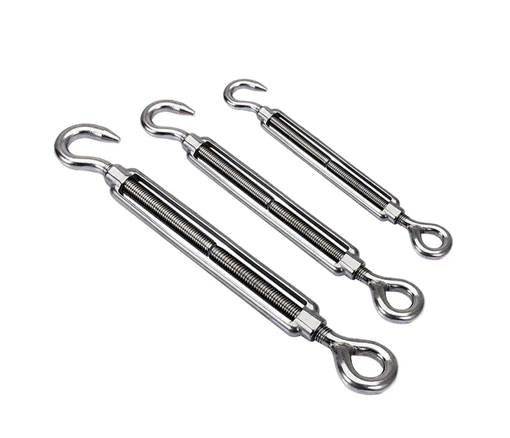
These combinations are primarily influenced by what the turnbuckles connect to. For example, a jaw connects points that do not open, such as a bolt. Conversely, an eye is used to connect points that can open, such as a shackle. Lastly, a hook is used to attach to a temporary connection.
Proper installation of any equipment is vital for safety and effectiveness, and turnbuckles are no exception. Installing a turnbuckle is simple with the following steps:
turnbuckles, we are equipped with a fully stocked inventory in our Orlando warehouse. For more help on finding the right supplies to fit your needs, contact us today at 1-800-486-5542.

These can be used for a variety of applications.Sail boats and yachts, cable railing, and for shade sails. Each turnbuckle body can be mixed and matched with jaw, eye and stud ends.
The present invention relates to turnbuckles, and in particular, to turnbuckles to be used with the standing riggings of sailing ships, and to a method of making such turnbuckles.
Turnbuckles are known in the art, and have been used for tightening a rod, strand or rope. Typical turnbuckles are made of metal, such as steel or brass, and typically have two threaded ends which receive the threaded ends of rods or the like. The threaded ends are threaded in opposite hand, so that by turning the turnbuckle the rods, strands or ropes on both ends may be loosened or tightened.
Turnbuckles have been used in sailing ships for pre-loading the mast or masts in tension. A ship"s standing rigging, such as the side stays that hold up the mast or masts, may be placed in tension to thereby place the mast or masts in tension by tightening turnbuckles attached to the stays. Loads of 100-30,000 pounds or more are typically placed on the turnbuckle.
The turnbuckles used on the side stays in sailing vessels may be located several feet above the water line, particularly if the mast has one or more spreaders. These metal turnbuckles therefore contribute not only to the overall weight of the ship, but also affect the center of gravity and overall stability of the ship. In so doing, the metal turnbuckles contribute to problems with moments and produce a multiplier effect due to the distance above the water line, requiring a higher weight keel to overcome the effects of the moments and multiplier.
In addition, the metal turnbuckles have been subject to oxidation, reducing their useful lives and detracting from the appearance of the products. This oxidation problem is worsened in the harsh environments encountered in sailing, particularly in the ocean sailing environment.
The present invention provides a turnbuckle of sufficient strength in tension to be used with the standing rigging of a ship, such as with the side stays, while substantially decreasing the weight of the turnbuckle. The turnbuckle of the present invention is made of two different materials. It includes a pair of metal end fittings and a body comprising a non-metallic material. The end fittings are co-axial and spaced from each other. The turnbuckle body extends between the end fittings. The body may comprise a matrix or composite material. The body and the end fittings are secured to limit relative axial movement between the end fittings and the body. Each end fitting has a threaded interior surface. Rod, strand or rope to be placed in tension may be received in the end fittings.
FIG. 8 is a perspective view of one stage of production of a turnbuckle of the type shown in FIG. 6, showing two end fittings and with reinforcing fiber material placed on the end fittings and without a matrix material.
FIG. 10 is a perspective view of one stage of production of a turnbuckle of the type shown in FIG. 6, showing the two end fittings of FIG. 9 and with reinforcing fiber material placed on the end fittings and without a matrix material.
The turnbuckle 10 of the present invention includes a pair of spaced annular end fittings 12 and a body 14 substantially surrounding and extending between the end fittings 12. The illustrated end fittings 12 are annular and are made of metal, such as brass or steel, and each has an interior threaded surface 11. The end fittings are spaced and have a common central axis 13. The interior threads of the end fittings are of opposite hand so that turning the turnbuckle in one direction or the other will loosen or tighten the connection with a rope or rod extending axially through the open interiors of the end fittings. The end fittings 12 have outer surfaces 16, as shown in FIGS. 4, 5, 7, 9, 13-18 and 21, outward faces 18 and inward faces 20.
The body 14 of the illustrated turnbuckle includes a pair of side arms 22, integral end jackets 24 surrounding the outer walls 16 of the end fittings 12, and an integral bridge 26 joining the arms 22 midway between the end fittings. The side arms 22 are spaced apart and are parallel to each other. The side arms extend between the end jackets 24, and have longitudinal axes 25 parallel to the common central axis 13 of the end fittings 12. The body 14 may be formed of a non-metallic material that preferably bonds with the outer surface 16 of each metal end fitting 12. The two outward ends 28 of the illustrated body have a reduced diameter, and the width of the arms 22 is less than the widest diameter of the jacket 24, as shown in FIG. 1. It should be understood that the turnbuckle body may have a different shape than that illustrated; for example, instead of two arms and an integral bridge between the end fittings, the turnbuckle body may be a solid structure; the turnbuckle may also be longer, shorter, thicker or thinner than illustrated, and the ends of the turnbuckle need not be tapered as shown. Moreover, the end jackets 24 may cover the ends 18, 20 of the fittings 12 or leave them exposed; other parts of the fittings 12 could also be exposed or covered.
To provide such varying diameters, end fittings such as those shown in FIGS. 5, 7, 9, and 13-18 may be used. As shown in FIGS. 5, 16-17, and 19-21, the outer surface 16 of the end fitting 12 may have a raised annular flange 30 or spiral ribs 31, so that the body jacket 24 forms a mating retaining lip or surface 76 that physically limits outward axial movement of the end fittings, as shown in FIG. 19. The end fitting 12 could also have a frusto-conical outer surface 16, with the larger outer diameter at the inward face 20 of the end fitting 12, with the jacket 24 having a mating contacting surface so that when the turnbuckle is placed in tension, the shape of the jacket contacting surface would physically limit outward axial movement of the end fittings. To provide areas for interference fit between the end fittings 12 and the body 14, the outer surfaces 16 of the end fittings 12 could have a variety of shapes and forms of recesses, indentations, and depressions, such as a series of annular recesses; alternatively, the end fitting outer surfaces 16 may have a variety of shapes and forms of protrusions, ridges, raised rings, shoulders and bumps. Mating structures in the jacket 24 of the body 14 would serve to limit relative axial movement between the fittings 12 and the body 14.
The reinforcing fibers and end fittings 12 may be encapsulated in a molded matrix or resin to form the body 14. The matrix or resin may comprise, for example, thermoplastic or thermosetting resin. Thermoplastic resins are those that harden by lowering their temperature below the glass transition temperature (amorphous thermoplastics) or below their melting temperature (semi-crystalline thermoplastics). Examples of suitable thermoplastic resins include polycarbonate resins such as LEXAN available from GE Plastics (GE Company) of Pittsfield, Mass., CALIBRE available from the Dow Chemical Co. of Midland, Mich., and MAKROLON available from the Bayer Corporation Polymer Divisions of Pittsburgh, Pa. Other suitable thermoplastic matrix material includes acrylics such as ACRYLITE available from CYRO Industries of Rockaway, N.J., and polyamide 66 such as ZYTEL available from DuPont Engineering Polymers (E. I. DuPont deNemours & Co., Inc.) of Wilmington, Del. and ASHLENE available from Ashley Polymers, Inc. of Brooklyn, N.Y. Suitable thermoplastics also include polyacetals such as CELCON available from Hoest Celanese Corp.--Technical Polymers of Summit, N.J. and DELRIN available from DuPont Engineering Polymers (E. I. DuPont deNemours & Co., Inc.) of Wilmington, Del. Polybutylene teraphthalate PBT may also be used. Thermoset resin or matrix materials are those that harden after undergoing a chemical reaction or cure, wherein the molecules cross-link to render a material that cannot by re-melted and reused. Examples of suitable thermoset resins include epoxy, vinyl ester and unsaturated polyester. A suitable epoxy is FARBOSET available from Farboil Company of Baltimore, Md.; a suitable vinyl ester is KINEL available from the Ciba-Geigy Corporation of Brewster, N.Y.; and a suitable unsaturated polyester is ROSITE available from the Rostone Corporation of Lafayette, Ind. These thermoplastic and thermoset matrix materials are generally available in different grades, and the grade may be selected based upon design parameters for the turnbuckle. Preferably the matrix material will bond to the outer surface 16 of the metal end fittings. It should be understood that the commercial matrix materials identified above are identified for purposes of illustration only, and the present invention is not limited to those products.
The matrix material may include standard fillers such as glass beads, ceramic powder and mineral filler, and the matrix material forming the body could include such fillers without any reinforcing fiber. The term "composite" as used herein is intended to include such matrices with reinforcing fiber and no filler, with filler and no reinforcing fiber, and with both reinforcing fiber and filler. Depending on the material selected for the body and design parameters for the turnbuckle, the body could also be made of matrix material without filler or reinforcing fiber. Thus, the body generally comprises a non-metallic material that may include a matrix or a composite; metallic elements, such as a metal wire, could also be included in the body. Generally, any suitable or desirable matrix material, reinforcing fiber and filler may be used that is compatible with the end fittings selected and produces a product that meets design parameters.
As shown in FIGS. 7-15, it may also be desirable to provide fiber supports 42 on the end fittings 12 on which elongate fibers 40 may be placed by winding, wrapping or looping fibers, or by positioning loops of fibers, as disclosed in the U.S. patent application entitled "Composite Article and Method of Making A Composite Article" filed concurrently herewith by William L. Foley, John D. Bush and Tim A. Osswald, and assigned to Amsted Industries, Inc., which is incorporated by reference herein in its entirety. As described in that patent application, and as shown in FIGS. 7-15, the end fittings 12 may have a pair of fiber supports 42 at the outer surfaces 16 of the end fittings 12, with elongate fibers 40 extending between the fittings 12 and over the fiber supports 42, as shown in FIGS. 8 and 10. It may be preferred to have an elongate fiber 40 extend over each fiber support more than once, as it is expected that the tensile strength of the composite body and its resistance to creep may be related to the number of wraps of the elongate fiber; creep may also be expected to be related to the length of the elongate fibers, with longer fibers being expected to result in less creep. Several elongate fibers 40 may be wrapped over the supports 42, and the wrapped elongate fibers could be used in combination with short randomly dispersed fibers in the matrix 41, with matrix and filler, with matrix filler and short reinforcing fibers, or with the matrix alone. The elongate fibers 40 need not all be of the same material: several different materials could be combined, and body could include lengths of wire in addition to or in place of the aramid, thermoplastic, glass or carbon fibers.
It may be desirable to combine the fiber supports 42 of FIGS. 7, 9 and 13-15 with a structure that provides an interference fit between the body 14 and end fitting 12 to further strengthen the end fitting/body interface against tension. Such a structure could include an indentation or groove in the outer surface 16 of the end fitting 12 and an inwardly expanding outer diameter of the end fitting. Such a groove could be beveled in one or two directions to further aid in providing this interference fit. With such fiber supports 42 on the end fittings, it should not be necessary to employ any additional structure or surface treatment to limit relative rotation between the end fittings and the body, since the fiber supports and mating body surfaces should prevent such relative rotation.
The present invention may be used in the same manner as a prior art turnbuckle. In use on a sailing ship, ends of rigging rope may be inserted through each opening in each end fitting 12 of the turnbuckle 10 and the turnbuckle turned as in the prior art to tighten the rigging to place the rigging and mast in tension. The weight of the turnbuckle of the present invention is expected to be about one-fourth on the weight of a similarly-sized metal turnbuckle. Since the turnbuckle of the present invention is much lighter weight than the prior art metal turnbuckles, the center of gravity of the ship or boat is not as high with the present invention, and the weight of the ship or boat is decreased. And since significantly less metal is used, oxidation is less problematic.
Different sizes of turnbuckles may be produced with different internal diameters. It may be desirable, for example, to produce turnbuckles of two body sizes and a range of thread sizes, for example, eight thread sizes, so that one die may be used to produce turnbuckles for different size boats and for different loads. It may be most efficient to have one body size for several different thread sizes, for example, with one die or mold for a body to be used with end fittings accepting one-quarter inch, three-eighths inch, five-sixteenths inch and three-quarter inch threads.
It may also be desirable to produce turnbuckles of several different sizes. With a range of body sizes, and with a range of strength ratings, designers of structures using the turnbuckle will be given a greater range of choices. Moreover, turnbuckles with different strength ratings can be produced within a given range of body sizes by varying the number of loops of elongate fibers placed on the fiber supports. Other production parameters may also be varied to produce different strength ratings.
In the prior art, typical one-piece all-metal turnbuckles for use in marine environments, such as in ship riggings, have been made to accept wire diameters of from about 3/32 inch to about 7/16 inch, and rod or pin diameters of from about 1/4 inch up to about 3/4 inch. Tensile strengths of these commercially available all-metal marine turnbuckles have ranged from about 3300 lbs up to about 29,000 lbs., with working loads being limited to about 40% of the tensile strength. To have utility in this environment of use, the turnbuckle of the present invention should exhibit a similar range of tensile strengths at lower weights. To assure meeting these tensile strengths, the matrix material, reinforcing material, filler, shape of the body, and shape, strength and material of the end fittings may be adjusted: for example, instead of using a commercially available end fitting, it may be desirable to produce an end fitting that, together with a composite body of matrix and reinforcing fibers, produces a composite retaining lip of sufficient strength to meet the desired tensile strength without the end fitting pulling out; for example, the depth and height of any recess in the end fittings, or the axial and longitudinal extent of any outcropping that forms a mating retaining surface 76 in the composite casting may be selected to assure that a mating retaining lip of adequate strength is formed in the molded composite body. It may also be desirable to thicken the jacket 24 surrounding the end fitting to strengthen the turnbuckle 10 against pullout of the end fittings 12. The weight and sizes of the remaining parts of the composite body 14, such as the arms 22, may also be adjusted to minimize the weight while achieving the desired tensile strength. For the purpose of minimizing weight, it may be desirable to provide a variety of body sizes for the turnbuckles.
The turnbuckles of the present invention can also be used as tension, connecting or anchoring members in other environments. For example, it is expected that the turnbuckles of the present invention may be used with guy wires, or in other areas where light weight and resistance to oxidation are desirable. It is expected that the present invention may also be used to produce other types of bodies, with fittings other than annular end fittings.


 8613371530291