
verope wire rope free sample
A distinction is made between the nominal rope diameter and the effective rope diameter. The nominal wire rope diameter is an agreed theoretical value for the diameter of the smallest circle circumscribing the outer strands.
The effective rope diameter, also called actual rope diameter, is the diameter of the smallest circle enclosing all outer strands, as measured on the rope itself. The tolerance range for the effective rope diameter is specified in related national and international standards. According to EN 12385-4 it is between -0{a889db705b9dbdba2a8d0dbcfc2b631547dc85af52ef75a70f044d2486ae0f02} and +5{a889db705b9dbdba2a8d0dbcfc2b631547dc85af52ef75a70f044d2486ae0f02} (for nominal rope diameters ≥ 8mm)
This means that the effective rope diameter upon delivery must neither be smaller nor bigger than 5{a889db705b9dbdba2a8d0dbcfc2b631547dc85af52ef75a70f044d2486ae0f02} than the nominal rope diameter. The tolerance range is often higher for smaller ropes like 3mm to 7mm nominal diameter. In the Oil and Gas industry, which is firmly based on US regulations, a tolerance range from -1{a889db705b9dbdba2a8d0dbcfc2b631547dc85af52ef75a70f044d2486ae0f02} to 4{a889db705b9dbdba2a8d0dbcfc2b631547dc85af52ef75a70f044d2486ae0f02} is applied. The effective rope diameter changes depending on the load applied. Therefore the effective rope diameter should in critical cases be measured on a rope that is loaded with 5{a889db705b9dbdba2a8d0dbcfc2b631547dc85af52ef75a70f044d2486ae0f02} of the calculated breaking strength. verope® produces standard tolerances of +2{a889db705b9dbdba2a8d0dbcfc2b631547dc85af52ef75a70f044d2486ae0f02} to +4{a889db705b9dbdba2a8d0dbcfc2b631547dc85af52ef75a70f044d2486ae0f02} and special tolerances upon request.
By the design of a wire rope, one understands the formation principle according to which the elements of the wire rope (the wires and the strands) are arranged relative to each other. The designation of a fiber core is FC, for an independent steel wire rope core it is IWRC. As an example all round strand ropes of the 6×19 Warrington design with a fiber core have the construction 6 x [1-6-(6-6)] – FC.
The fill factor of a rope is defined as the ratio of the metallic cross section of the rope (or a simplified calculation of the sum of the single wire cross sections) related to the nominal rope diameter. The fill factor specifies which amount of space the wires and strands take in the rope (figure 16).
The fill factors of the most common ropes are between 0,46 and 0,75. This means, that the amount of steel in the rope volume is about 46{a889db705b9dbdba2a8d0dbcfc2b631547dc85af52ef75a70f044d2486ae0f02} to 75{a889db705b9dbdba2a8d0dbcfc2b631547dc85af52ef75a70f044d2486ae0f02}. Wire ropes with a wire rope core have higher fill factors than ropes with a fiber core.
Usually fill factors of wire ropes with a fibre core (FC) decrease with an increasing number of outer strands. A rope of the design 6×25 Filler-FC has a fill factor of 0,50, a rope of the design 8×25 Filler-FC has only a fill factor of 0,445.
Usually fill factors of wire ropes with a wire rope core increase with an increasing number of outer strands. A rope of the design 6×25 Filler-IWRC has a fill factor of 0,58 and a rope of the design 8×25 Filler-IWRC has a fill factor of 0,587.
Two lay types are to be considered: Regular or ordinary lay and lang’s lay. In regular lay ropes, the lay direction of the wires in the strands is opposite to the lay direction of the strands in the rope. We distinguish between right hand ordinary lay RHOL (right hand strand, left hand rope, zS) (figure 17) and left hand ordinary lay LHOL (left hand strand, right hand rope, sZ) (figure 18). In lang’s lay ropes, the lay direction of the wires in the strands is equal to the strands in the rope. We distinguish between left hand lang’s lay LHLL (left hand strand, left hand rope, sS) (figure 19) and right hand lang’s lay RHLL (right hand strand, right hand rope, zZ) (figure 20).
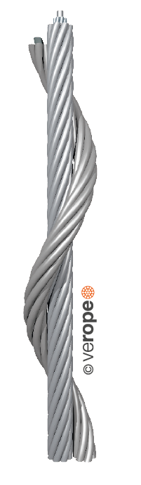
In the stranding process the initially straight wires are forced into a helical or double-helical form. Therefore, the wires in a rope are always under tension, even in an unloaded rope. Such a rope must be sealed very tightly left and right of the joint before cutting the rope because otherwise the free ends of the wires will spring open. By using a “preforming tool”, the wires and strands can be heavily plastically deformed during the stranding, so are laying nearly without tension in the rope, the rope now is preformed. The ropemakers consider such ropes to be “dead”. Preformed ropes can be cut much easier, also secured by seizings of course, than nonpreformed ropes.
Usually wire ropes have either a fiber core (FC) or a steel/wire core. The steel/wire core can be a strand (WC) or a small rope, named as independent wire rope core (IWRC). The IWRC can be made in a separate operation or during the closing operation of the wire rope (PWRC). The wire core can also have a plastic coating (EPIWRC). Cores made of compacted strands have the additional designation (K). An independent wire core made of compacted strands is therefore called IWRC (K). A rope closed in a single operation and made out of compacted strands both in the core and the outer strands is called PWRC (K).
wire ropes and their free rope end rotate to a greater or lesser extent around its longitudinal axis under the influence of tension. Wire ropes having a core lay direction opposite to the lay direction of the outer strands and 3- or 4-strand regular lay wire ropes rotate considerably less than wire ropes with the same lay direction of the wire core and the outer strands and wire ropes with fiber cores. According to VDI 2358, a wire rope is semi rotation-resistant when: “the wire rope which turns around its longitudinal axis when subjected to unguided load and/or hardly transmits a torque to the attachment at the end in the event of guided rope ends.”
According to ISO 21669 and DIN EN 12385-3: “a rope is considered to be semi rotation resistant if it rotates at least once and at most four times around its axis at a length of 1000 x d under a load of 20 {a889db705b9dbdba2a8d0dbcfc2b631547dc85af52ef75a70f044d2486ae0f02} of the minimum breaking force. In terms of rotation angle, the defined limits are between 360° and 1440°.”
According to the regulation of VDI 2358, a wire rope is rotation-resistant, when: “the wire rope, which hardly turns around its longitudinal axis when subjected to unguided load and/or hardly transmits a torque to the attachment at the end in the event of guided rope ends.”
The wire rope lubricant has two major tasks: it should protect the rope from corrosion and minimize the friction between the rope elements themselves and between the rope and the sheave or the drum. A reduction of the friction reduces the actuating power and minimizes the wear of the rope, the sheaves and the drums. We differentiate between wax-based lubricants and oil-based lubricants. While wax-based lubricants offer a better handling of the ropes, the oil-based lubricants advantage is a better closing of the lubrication film due to the gravitational force of the oil. The quality of the wire rope lubricant has a great impact on the fatigue resistance of a wire rope (figure 22).

Note: 1) Please note that a counted broken wire always has two ends. 2) Shall be applied exclusively to those sections of rope running only over steel sheaves
and/or spooling on a single-layer drum. For single layer spooling ordinary lay ropes have to be used. The wire breaks are randomly distributed. 3) Shall be applied
exclusively to those sections of rope spooling on a multi-layer drum. 4) The values are valid only in conjunction with footnote 3 and apply to deterioration that occurs
at the cross-over zones and interference between wraps due to fleet angle effects. Note: These values do not apply to those sections of rope running only over
sheaves but do not spool on the multi-layer drum! 5) d = nominal rope diameter 6) Twice the number of broken wires listed may be applied to ropes on mechanisms
Danger: Rope selections made contrary to expertise or generally applicable regulations have an accelerated failure mechanism. In extreme cases, an incorrect rope selection can lead
This method requires a great deal of force and is time-consuming, depending on the rope length. However, if no other method is available, this procedure is
Notes: 1) Please note that a counted broken wire always has two ends. 2) Shall be applied exclusively to those sections of rope running only over steel sheaves
and / or spooling on a single-layer drum. For single layer spooling ordinary lay ropes have to be used. The wire breaks are randomly distributed. 3) Shall be applied
exclusively to those sections of rope spooling on a multi-layer drum. 4) The values are valid only in conjunction with footnote 3 and apply to detoriation that occurs at
the cross-over zones and interference between wraps due to fleet angle effects. Note: These values do not apply to those sections of rope running only over sheaves
but do not spool on the multi-layer drum. 5) d = Nominal rope diameter 6) Twice the number of broken wires listed may be applied to ropes on mechanisms whose
RCN = Rope Category Number | b Tick as applicable. | c Describe degree of deterioration as: slight (20%), medium (40%), high (60%), very high (80%) or discard (100%)
task, several runs of normal operation should be carried out under light load. The new rope should be “incorporated� so that the elements can settle and adapt
With the following hints we would like to draw your attention to some essential points for correct selection, operation and maintenance of wire ropes. In addition to technical literature on wire ropes, national and international
necessary to remove the rope or end connection according to manufacturer specifications. For questions, ambiguities or problems, please contact the customer service
Danger: Rope selections made contrary to expertise or generally applicable regulations have an accelerated failure mechanism. In extreme cases, an incorrect rope selection can lead

The fill factor of a strand is defined as the ratio of the metallic cross section (or as simplified calculation the sum of the single wire cross sections) related to the area of the smallest circle circumscribing the strand. The fill factor specifies the amount of space which the strand takes in the rope meaning the amount of steel. The fill factors of the most common strands are between 0,70 and 0,82. This means, that the amount of steel in the strand is about 70% to 82%. The fill factors of strands can be considerably increased by compacting. Usually the fill factor of a strand increases with an increasing number of wires. A Seale 15 strand (1-7-7) for example has a fill factor of about 0,77 and a Seale 19 strand (1-9-9) has a fill factor of about 0,79.
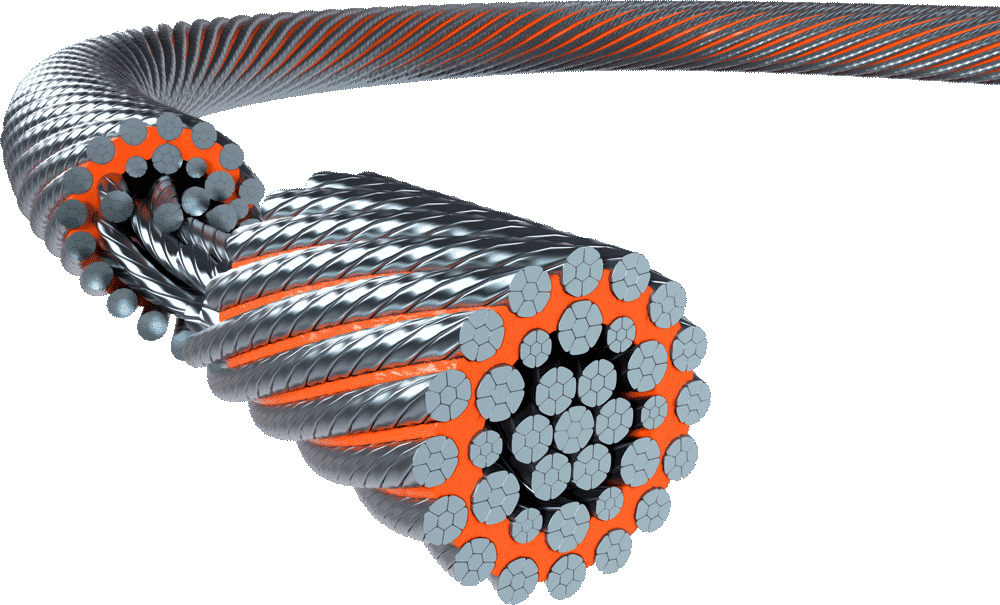
Many verope products have a plastic layer between the steel core and the outer strands. This intermediate layer stabilizes the form stability of the rope like a flexible corset and increases the lifetime of a rope especially under difficult working conditions. The intermediate plastic layer avoids the infiltration of water and dirt, which helps avoiding corrosion in the steel core. This cushion avoids internal steel-to-steel cross over contacts and limits as such the damage caused by this phenomenon (figure 29).
verope Special Wire Ropes are designed to achieve high breaking loads and better strength to weight ratios. High ductility wires drawn to controlled tolerances are stranded and closed into a rope constructed with optimized gap spacing between the individual rope elements. verope products achieve an increased fill factor by using compacted strands as well as rotary swaging in their method of rope construction. Parallel lay elements in the rope composition increase the metallic cross sectional area. Crane designers use the technical advantages provided by the rope manufacturers to reduce the drum and sheave dimensions in line with maintaining the recommended D/d ratios. The material cost and weight saving effect on the static design of the crane elements is substantial.
The minimum breaking strengths that is given in catalogs is valid for wire ropes whose ends are protected against twisting. The breaking strengths of non-rotation resistant ropes is reduced significantly by the usage of a swivel. Even if the rope would not immediately break under the nominal load, several now overloaded elements of the rope will disproportionally become fatigued. Also structural changes, like basket deformation could appear very fast. Therefore non-rotation resistant ropes should not be used with a swivel.
verope operates the first two bending fatigue machines world-wide built according to a revolutionary concept. The steel wire rope is installed in the test machine, put under tension, and then the rope travels back and forth over five test sheaves until it finally breaks in the middle. Only then the rope analysis starts: To the left and to the right of the broken section, which during the test has travelled back and forth over five sheaves, the machine has rope sections which only travel over four sheaves and don’t make it to the fifth. Regardless of what the number of cycles to failure will be, these sections will always have made 80% of this number. These sections, and the further sections which will have travelled over 3, 2, 1 and 0 sheaves only and which will represent the condition of the rope after 60%, 40, 20% and 0% of the rope life are cut out for analysis (figure 35).
One of the two sections of each condition is used to determine the number of external wire breaks and the changes in rope diameter and lay length. Then the section is taken apart in order to also determine the number of internal wire breaks on the underside of the outer strands, on the outside and inside of the IWRC and on individual strands as well as changes in the IWRC and strand diameters and lay lengths. This way the sections will tell you how the external wire breaks develop over the lifetime of the rope, how the internal wire breaks develop over time, how the plastic infill looks at different stages of the rope life and which elements start to deteriorate first. These results can help verope. to improve the product design of a new ope after only a single test. The comparable 80%, 60%, 40%, 20% and 0% sections on the other side of the break are subjected to pull tests to destruction. This way verope. can determine how the strength of this rope design, its modulus of elasticity and its elongation at break develops over the lifetime of the rope. A steel wire rope should have a breaking strength as high or higher than new until it reaches the discard number of wire breaks (figure 34).
figure 34: Rope breaking strength in % of the breaking strengths of a new rope dependent on the lifetime until break. A steel wire rope should have a breaking strength as high or higher than new until it reaches the discard number of wire breaks.
Due to the detailed analysis of the several working sections, the development of external wire breaks over the lifetime can be evaluated very precise (figure 42).
figure 42: Number of visible (pulled trough line) and invisible wire breaks (sketched line) dependent on the rope lifetime. After the ending of the bending fatigue test the analysis of the rope sections with the different fatigue numbers shows the marked numbers of wire breaks.
On disassembling the rope pieces the internal wire breaks depending on the lifetime can be evaluated (figure 43). At the veropro 8 construction the number of visible wire breaks is higher than the number of internal (invisible) wire breaks.
Bending fatigue tests are taken normally until the break of the rope or a strand. The exact point of discard can be determined by evaluating the single rope sections.
The lifetime of a rope is significantly influenced by the sheave material. By the use of plastic sheaves the bending fatigue rises clearly in comparison to the use of steel sheaves. The remaining “rest-lifetime” of the rope after the achievement of the discard criteria until the break of the rope, is with regard of the bending cycles more or less the same, nevertheless it drops significantly in percentage. Therefore the rope inspection must be carried out especially carefully when using plastic sheaves. verope recommends plastic sheaves, hence, only in applications where the ropes are checked magnet-inductively or where the rope gets damaged primarily outside like in multi-layer spooling (figure 49).
A comparison of the bending fatigue of ungalvanized and galvanized ropes until the achievement of the discard criteria according to ISO 4309 and until break of the rope shows, that galvanized ropes usually reach more bending cycles. The zinc coating offers better “emergency operating features” when the rope is not lubricated any more and protects the rope from friction corrosion (figure 50).
According to ISO 4309 the groove of a sheave should have a diameter, that is 5% to 10% bigger than the rope diameter. During the operating time, the rope diameter will decrease. With this decreased diameter the rope will dig itself in the sheave groove and will reduce the groove diameter. Therefore, with the installation of the rope it should be considered, that the groove diameter of the sheave is at least 1% bigger than the measured rope diameter. If the groove diameter is too big, the support of the rope is not very good anymore and the surface pressure increases. Consequently the lifetime of the rope decreases steadily with an increasing groove diameter. If the groove diameter is too small, the rope will be squeezed and the lifetime d Steel sheaves rops extremely.
The applied diameters of the sheave as well as the diameters of the drums have a huge impact on the lifetime of a rope. In the shown example a rope running over a sheave with a diameter of 800mm still reaches more than 2.000.000 bending cycles, the bending condition reduces by halving the diameter of the sheave to 400mm to 290.000 bending cycles (figure 53).
In many applications the exact knowledge of the deformation behavior of wire ropes is of great importance. verope. has investigated in many work-intensive tests the modulus of elasticity (lengthwise and transverse), the elastic and plastic deformation as well as the diameter reductions of its products. Many technical parameters of the rope can be determined by the creation of a load-elongation diagram (figure 54). verope. loads and relieves the ropes in steps and determines out of this the elongation under load as well as the remaining elongation after discharge. The elasticity modulus is determined from the gradient of the linear area of the load curves. At the same time the diameter reduction in dependence of the load is measured. In order to be able to determine also the breaking strength and the elongation at break, the ropes are loaded up to the break.
Within a rope construction the modulus of elasticity varies slightly in dependence of the rope diameter, the lay type (lang’s lay or regular lay) and of the tensile strength of the wire (figure 55). As a rule, the modulus of elasticity of wire ropes increases over the lifetime of the rope.
In particular with suspension ropes, but also with running ropes an exact knowledge of the elongation of the rope under load and the remaining rope lengthening after load is important. verope has measured these relevant values for all its products with high precision on long test lengths. You will find here measured values of typical verope rope constructions. We are pleased to provide you with the results of other verope rope construction for your interpretations.
A rope becomes longer and thinner under load. The diameter reduction can influence the rope behavior in multi-layer spooling strongly. verope has measured the diameter reduction of all its products and will be pleased to provide you with the measured values if required.
In multi-layer spooling wire ropes are additionally to tensile and bending loads exposed to enormous transverse loads. In order to be able to withstand these loads and to avoid spooling problems, a high degree of radial stability is necessary. The radial stability of the rope also influences the deforming behavior of the drum. That’s why it is important for the designer of the drum to know the radial stability in the form of the transverse modulus of elasticity of the ropes. Radial stability is defined as the resistance of a wire rope against transverse (radial) deformation (Ovalization). verope measures the radial stability of its products with (figure 62) and without load (figure 60 & 61).
At the determination of the transverse modulus of elasticity under load the deformation behavior of the rope is measured under various tensile loads and different transverse loads (figure 62). verope has determined the transverse modulus of elasticity for all its products and will be pleased to provide them to designers when required.
To evaluate the rotational behavior of a wire rope the rope torque and the rotation angle are measured. For the measurement of the rotation angle a smooth swivel is fastened at the end of the rope. During the test the twist of the rope is measured in dependence of the load. The twist usually is given in degree per 1000 x rope diameter. To measure the rope torque both rope ends are protected against twisting. At one end of the rope the rope torque in dependence of the load is measured, with which the rope wants to twist the end-fitting.
The flexibility of a rope is a measure of how easily a rope allows itself to bend around a given diameter. The flexibility of a rope is among other things dependent on the line pull. The flexibility of an unloaded rope can be measured by the sag of a rope under its own weight. Figure 67 shows the maximum sag of the rope for different free rope lengths (expressed as a multiple of the rope diameter). The flexibility of ropes under load is measured as the efficiency factor of the rope while running over a sheave.
Figure 68 shows a typical diagram of a rope efficiency factor under line pull. In many specified standards one finds the reference, that for dimensioning a reeving system using roller bearings it should be calculated with an efficiency factor of 0.98, this value is marked in figure 68. However, the designer of a reeving system needs the efficiency factor under high line pulls (area B in the diagram, here the efficiency factor is higher than 0.98) for the calculation of the required drive power. In order to calculate the minimum weight of the unloaded bottom hook block the designer needs the efficiency factor under relatively low line pulls (area A in the diagram, here the efficiency factor is clearly lower than 0.98). To help the designer in his interpretation, verope measures the efficiency factor of its products in the low-load range and in the range of high loads with high accuracy(figure 69 & 70).
As the very first special wire rope manufacturer, verope has measured the efficiency factor of its products over the lifetime of the ropes. Typically the efficiency factor of the rope improves first over the lifetime and drops later to reach the initial value at discard. Figure 71 shows a typical example. Under higher loads the efficiency factor of verope special wire ropes with a D/d ratio of 20 or higher lies demonstrably above 0.99. Therefore shall for example cranes that are certified by Germanischer Lloyd using various verope special wire ropes be interpreted with an efficiency factor of 0.99. Please contact us for further details.

2 Contents 1. Rope Technology Basics 1.1 All about wire Raw material Manufacturing process Wire surfaces Wire forms Wire tensile strength 1.2 All about the strand Lay length of a strand Lay direction of a strand Diameter of a strand Strand design Compacted round strands Fill factor of a strand 1.3 All about the rope Wire rope diameter Measuring Devices and their correct handling Types of measuring devices Lay direction of a wire rope Rope design Fill factor of a rope Lay types of wire ropes Low-tension wire ropes Types of rope cores (abbreviated designations according to EN ) Semi rotation-resistant wire ropes Rotation-resistant wire ropes Wire rope lubricant & Re-lubrication 2. Rope Characteristics 2.1 Breaking strength 2.2 Bending fatigue resistance 2.3 Flexibility 2.4 Efficiency factor 2.5 Wear resistance 2.6 Deformation Behavior Modulus of elasticity Radial stability Structural stability Diameter reduction of a special wire rope 3. Why special wire ropes? 3.1 Plastic Layer 3.2 Breaking Strengths Breaking strengths and Swivel 3.3 Bending fatigue and rope lifetime Bending fatigue when using steel or plastic sheaves Bending fatigue of ungalvanized and galvanized ropes Bending fatigue in dependence on the groove diameter Bending fatigue in dependence on the line pull Bending fatigue in dependence of the sheave diameter Page 4 Page 4 Page 4 Page 4 Page 4 Page 4 Page 4 Page 5 Page 5 Page 5 Page 6 Page 6 Page 8 Page 8 Page 10 Page 10 Page 10 Page 11 Page 12 Page 12 Page 12 Page 13 Page 14 Page 14 Page 14 Page 14 Page 16 Page 17 Page 17 Page 17 Page 17 Page 18 Page 18 Page 20 Page 20 Page 22 Page 22 Page 22 Page 23 Page 23 Page 24 Page 25 Page 25 Page 30 Page 30 Page 31 Page 32 Page 32 2
3 3.4 Deformation behavior Modulus of elasticity Elongation Diameter reduction Radial stability with and without load 3.5 Rotational Behavior 3.6 Flexibility 3.7 Efficiency Factor 4. Discard Criteria (ISO 4309) 5. Crane components 5.1 Drums 5.2 Sheaves 6. Choose the right rope for your application 6.1 Application view 6.2 Rope view Hoist Application Usage of a swivel on hoist ropes More crane applications 6.3 Application of ordinary (or regular) lay and lang s lay ropes Ordinary lay ropes Lang s lay ropes 7. Rope requirements from the crane view 8. Rope End-fittings 8.1 Points of reference to determine the rope length precisely 8.1 Efficiency factor K T of rope end-fittings 9. General Information 9.1 Handling and Storage of ropes Handling of reels Rope Storage 9.2 Installation of wire ropes Control of the new rope Inspection of sheave grooves Rope Installation Process Initial operation after installation process Rope installation with multi-layer spooling Importance of preliminary tension of ropes with multi-layer spooling 10. Safety Instructions 11. Use of metrical ropes on imperial cranes and of imperial ropes on metrical cranes 12. verope Service and R&D Center 13. Worldwide service and distribution Page 33 Page 34 Page 35 Page 36 Page 37 Page 39 Page 40 Page 40 Page 42 Page 44 Page 44 Page 44 Page 46 Page 46 Page 46 Page 46 Page 48 Page 50 Page 52 Page 52 Page 52 Page 54 Page 56 Page 56 Page 56 Page 58 Page 58 Page 58 Page 58 Page 59 Page 59 Page 60 Page 61 Page 62 Page 62 Page 63 Page 64 Page 66 Page 68 Page 70 3
4 Rope Technology Basics All about wire Raw material Wires are usually made from specifi ed carbon steel. The carbon content is between 0,4% and 1%, the manganese content between 0,3% and 1%, the silicon content between 0,1% and 0,3% and the contents of phosphorus and sulphur each under 0,45%. Manufacturing process Wire rod of 6 to 9mm diameter, the raw material, will be transformed to the desired strength, diameter or shape by rolling or drawing in a cold forming process. Wire surfaces Galvanized wires are zinc coated by going through a bath of liquid zinc. The wire is called fi - nally galvanized if it does not get drawn further after this process. If the wire cross section is further reduced after this process, the wire is called drawn galvanized. Bright wires, uncoated, are indicated with the capital letter U, whereas zinc coated wires are divided into class A and class B, depending on the a zinc weigth coating Wire forms A distinction is made between the wire shapes. A round wire is a wire with a round cross section. Every wire that has a non-round cross section is called a profi led wire. There are oval wires, fl at wires, Z- and S-profi led wires, H-shaped wires, trapezoidal or wedge shaped wires and triangular wires. Profi led wires are produced by drawing or rolling processes. Wire tensile strength The tensile strength of a wire is defi ned as the maximum tensile force a wire can stand in longitudinal direction without breaking, divided by the cross section of the wire. The nominal tensile strength of a wire is a theoretical value, the actual tensile strength of the wire should not fall below the nominal tensile strength and should only exceed it in defi ned limits. Rope wires with the nominal tensile strengths of 1770 N/mm2, 1960 N/mm2 and 2160 N/mm2 are commonly used in modern wire ropes. 4
5 All about the strand A strand consists of one or multiple layers of wires, which are wound in a helical shape around an insert (figure 1). 2 nd Layer (Outer Wires) 1 st Layer Insert (Core Wire) Figure 1: Components of a strand Figure 2: left hand lay Figure 3: right hand lay Lay length of a strand The lay length of a strand is generally understood as the pitch of the helical lay of the wires, which means the lengths of a strand at which the wire circulates completely one time. By varying the lay length, the contact conditions of adjacent wires, the elastic properties and the breaking strength of a strand can be changed. Lay direction of a strand A distinction is made between right hand and left hand lay strands. The lay direction is left hand, when (moving away from the beholder) the wires are rotated counterclockwise (figure 2). The lay direction of a strand is right hand, when its wires (moving away from the beholder) are rotated clockwise (figure 3). The lay direction of a strand is often given by small s for the left hand lay strand and by a small z for the right hand lay strand. 5
6 Figure 4: Diameter of a strand Diameter of a strand Diameter of a strand The diameter of a strand is the diameter of the smallest, all wires enclosing enveloped circle. The strand diameter is usually measured with a micrometer caliper and is given accurate to 1/100mm (figure 4). Strand design One understands the formation law by the design of a strand according to which the wires are relatively to each other arranged. So all strands of the design Seale have for example the construction 1 - n - n with n=3, 4, 5, 6, 7, 8, 9.. wire layers, which get stranded parallel to each other in a single operation. According to EN these are connected by a minus - sign in the designation. 6
7 Figure 5: Standard strand Figure 6: Parallel lay strand 1+N Seale The name of a Seale strand design Seale 17 is therefore 1-8-8, the designation of a strand design Seale 19 is S15 S17 S19 S21 The most important strand designs are one-, two and three layer standard strands (figure 5), as well as parallel lay strands of the strand designs Seale, Filler, Warrington and Warrington-Seale (figure 6 & 7). Warrington W13 W16 W19 W22 The two and three-layer standard strands show crossovers between the wires of the different wire layers (figure 5). Here the wire layers get stranded in separate operations in the same direction (designation N) with a same stranding angle but with different lay lengths. Filler F17 Warrington-Seale F21 F25 F29 The so called parallel lay strands (Seale, Filler, Warrington, Warrington-Seale) avoid crossovers and create line contact of the wires instead. This happens due to a stranding of all wire layers at once with different stranding angles but the same lay length (figure 6 & 7). WS26 WS31 Figure 7: Strand designs WS36 WS41 7
8 Compacted round strands A compacted round strand starts as a conventional torsion free round wire strand. The strands are compacted either during stranding or in a separate operation afterwards to form a smaller diameter by rolling or drawing. The originally round wires are heavily deformed by both the compacting tool and the adjacent wires (figure 8). Fill factor of a strand The fi ll factor of a strand is defi ned as the ratio of the metallic cross section (or as simplifi ed calculation the sum of the single wire cross sections) related to the area of the smallest circle circumscribing the strand. The fi ll factor specifi es the amount of space which the strand takes in the rope meaning the amount of steel. The fi ll factors of the most common strands are between 0,70 and 0,82. This means, that the amount of steel in the strand is about 70% to 82%. The fi ll factors of strands can be considerably increased by compacting. Usually the fi ll factor of a strand increases with an increasing number of wires. A Seale 15 strand (1-7-7) for example has a fi ll factor of about 0,77 and a Seale 19 strand (1-9-9) has a fi ll factor of about 0,79. Figure 8: Uncompacted and compacted round strands 8
10 All about the rope Wire rope diameter A distinction is made between the nominal rope diameter and the effective rope diameter. The nominal wire rope diameter is an agreed theoretical value for the diameter of the smallest circle circumscribing the outer strands. The effective rope diameter, also called actual rope diameter, is the diameter of the smallest circle enclosing all outer strands, as measured on the rope itself. The tolerance range for the effective rope diameter is specified in related national and international standards. According to EN it is between -0% and +5% (for nominal rope diameters 8mm) This means that the effective rope diameter upon delivery must neither be smaller nor bigger than 5% than the nominal rope diameter. The tolerance range is often higher for smaller ropes like 3mm to 7mm nominal diameter. Measuring devices and their correct handling In order to define the correct effective rope diameter, the correct measuring device has to be used. The measurement should strictly be done over the round ends (circumscribed circle of the rope). If one measures in the strand valleys, the result will be inacurate. For ropes with an uneven number of outer strands, it is important that the measuring surface covers several strands (figure 10). WRONG In the Oil and Gas industry, which is firmly based on US regulations, a tolerance range from -1% to 4% is applied. The effective rope diameter changes depending on the load applied. Therefore the effective rope diameter should in critical cases be measured on a rope that is loaded with 5% of the calculated breaking strength. verope produces standard tolerances of +2% to +4% and special tolerances upon request. RIGHT Figure 10: Correct determination of the rope diameter 10
12 Lay direction of a wire rope A distinction is made between right hand and left hand lay ropes. The lay direction is left hand, when the strands (moving away from the beholder) are rotated counterclockwise (figure 14). The lay direction of a rope is right hand, when its strands (moving away from the beholder) are rotated clockwise (figure 15). The lay direction of a rope is often given by a capital S for the left hand lay rope and by a capital Z for the right hand lay rope. Others often use RH for Right Hand and LH for Left Hand lay ropes. Rope design By the design of a wire rope, one understands the formation principle according to which the elements of the wire rope (the wires and the strands) are relatively arranged to each other. The designation of a fi ber core is FC, for an independent steel wire rope core it is IWRC. As an example all round strand ropes of the 6x19 Warrington design with a fi ber core have the construction 6 x [1-6-(6-6)] - FC. Fill factor of a rope The fi ll factor of a rope is defi ned as the ratio of the metallic cross section of the rope (or a simplifi ed calculation of the sum of the single wire cross sections) related to the nominal rope diameter. The fi ll factor specifi es which amount of space the wires and strands take in the rope (figure 16). The fi ll factors of the most common ropes are between 0,46 and 0,75. This means, that the amount of steel in the rope volume is about 46% to 75%. Wire ropes with a wire rope core have higher fi ll factors than ropes with a fi ber core. A rope of the design 6x25 Filler-FC for example has a fi ll factor of 0,50 and a rope with a design 6x25 Filler-IWRC has a fi ll factor of 0,58. Figure 14: Left hand lay rope Figure 15: Right hand lay rope Usually fi ll factors of wire ropes with a fi bre core (FC) decrease with an increasing number of outer strands. A rope of the design 6x25 Filler-FC has a fi ll factor of 0,50, a rope of the design 8x25 Filler-FC has only a fi ll factor of 0,
13 Figure 16: The fi ll factor of the strand is the proportion of the metallic cross sections (white surfaces) at the metall cross section area of the minimum circumscribed circle (white and grey surfaces). Usually fi ll factors of wire ropes with a wire rope core increase with an increasing number of outer strands. A rope of the design 6x25 Filler-IWRC has a fi ll factor of 0,58 and a rope of the design 8x25 Filler-IWRC has a fi ll factor of 0,587. Figure 17: Regular lay left hand (zs) Figure 18: Regular lay right hand (sz) Wire ropes that are made of compacted strands have higher fi ll factors than ropes of uncompacted strands. By compacting and rotary swaging of the rope itself the fi ll factor can further be increased. Lay types of wire ropes Two lay types are to be considered: Regular or ordinary lay and lang s lay. Figure 19: Lang s Lay left hand (ss) Figure 20: Lang s Lay right hand (zz) In regular lay ropes the lay direction of the wires in the strands is opposite to the lay direction of the strands in the rope. We distinguish between regular lay left hand (right hand strand, left hand rope, zs) (figure 17) and regular lay right hand (left hand strand, right hand rope, sz) (figure 18). In lang s lay ropes the lay direction of the wires in the strands is equal to the strands in the rope. We distinguish between lang s lay left hand (left hand strand, left hand rope, ss) (figure 19) and lang s lay right hand (right hand strand, right hand rope, zz) (figure 20). The advantages of regular lay ropes are: Better structural stability Higher number of broken wires are allowed Easier identifi cation of broken wires The advantages of lang s lay ropes are: Better contact in the groove of the sheaves Superior resistance to wear Longer lifetime in case of high dead loads Considerably better spooling behavior on a multi-layer drum 13
14 Low-tension wire ropes In the stranding process the initially straight wires are forced into a helical or double-helical form. Therefore the wires in a rope are always under tension even in an unloaded rope. Such a rope must be sealed very tightly left and right of the joint before cutting the rope because otherwise the free ends of the wires will spring open. By using a preforming tool the wires and strands can be deformed during the stranding strongly and plastically so they are laying nearly without tension in the rope, the rope now is preformed. The ropemakers consider such ropes to be dead. Preformed ropes can be cut much easier, also secured by seizings of course, than non-preformed ropes. Types of rope cores (abbreviated designations according to EN ) Usually wire ropes have either a fiber core (FC) or a steel/wire core. The steel/wire core can be a strand (WC) or a small rope, named as independent wire rope core (IWRC). The IWRC can be made in a separate operation or during the closing operation of the wire rope (PWRC). The wire core can also have a plastic coating (EPIWRC). Cores made of compacted strands have the additional designation (K). An independent wire core made of compacted strands is therefore called IWRC (K). A rope closed in a single operation and made out of compacted strands both in the core and the outer strands is called PWRC (K). Semi rotation-resistant wire ropes Wire ropes with a free rope end rotate to a greater or lesser extent around its longitudinal axis under the influence of tension. Wire ropes having a core lay direction opposite to the lay direction of the outer strands and 3- or 4-strand regular lay wire ropes rotate considerably less than wire ropes with the same lay direction of the wire core and the outer strands and wire ropes with fiber cores. According to VDI 2358, a wire rope is semi rotation-resistant when: the wire rope which turns around its longitudinal axis when subjected to unguided load and/or hardly transmits a torque to the attachment at the end in the event of guided rope ends. According to ISO and DIN EN : a rope is considered to be semi rotation resistant if it rotates at least once and at most four times around its axis at a length of 1000 x d under a load of 20 % of the minimum breaking force. For the twist angle, this implies: 360 < φ <1440. Rotation-resistant wire ropes According to the regulation of VDI 2358 a wire rope is rotation-resistant when: the wire rope, which hardly turns around its longitudinal axis when subjected to unguided load and/or hardly transmits a torque to the attachment at the end in the event of guided rope ends. 14
15 According to ISO and DIN EN : a rope is considered to be rotation resistant if it rotates around its axis at most once at a length of 1000 x d under a load of 20 % of the minimum breaking force. The rotation can be exhibited here in rope closing or rope opening sense. For the twist angle, this implies : 360 < φ > 360 (figure 21). Figure 21: Rotation-resistant rope verotop: the torques of the rope core and the layer of outer strands, generated under load, work in opposite directions. 15
16 Wire rope lubricant The wire rope lubricant has two major tasks: it should protect the rope from corrosion and it should minimize the friction between the rope elements themselves and between the rope and the sheave or the drum. A reduction of the friction reduces the actuating power and minimizes the wear of the rope, the sheaves and the drums. We differentiate between wax-based lubricants and oil-based lubricants. While wax-based lubricants offer a better handling of the ropes, the oil-based lubricants advantage is a better closing of the lubrication fi lm due to the gravitational force of the oil. Re-lubrication Generally wire ropes are lubricated intensively during the production process. Nevertheless, this initial lubrication has to be renewed regularly during the whole rope s lifetime. A regular re-lubrication contributes to an increase in the rope s service life (figure 23). The lubricant used for re-lubrication needs to be compatible with the lubricant used during production. It is advised to follow the maintenance instructions in ISO The quality of the wire rope lubricant has a great impact on the fatigue resistance of a wire rope (figure 22) [%] [%] Dry rope Lubricant 1 Lubricant 2 Lubricant 3 Dry rope Basic lubrication Basic lubrication & re-lubrication Figure 22: Wire rope lubricant impact on the fatigue resistance of the wire rope Figure 23: Infl uence of the re-lubrication on the lifetime of a rope 16
17 Rope Characteristics Breaking strength The calculated breaking strength of a steel wire rope is defined as the metallic cross section of a steel wire rope (the sum of the individual cross sections of all the wires making up the rope) multiplied by the nominal tensile strength of the steel wire rope. The minimum breaking strength of the steel wire rope is the calculated breaking strength of the rope multiplied by the spin factor. The actual breaking strength of a steel wire rope is the breaking strength of the rope as determined in a pull test. A new steel wire rope must achieve an actual breaking strength equal to or higher than the minimum breaking strength. The breaking strength of a steel wire rope can be increased by increasing the metallic area of the rope (e.g. by using strands with higher fill factors, by compacting the strands or by swaging the rope), by increasing the tensile strengths of the individual wires or by increasing the spin factor of the rope. This can also be achieved by improving the contact conditions between the rope elements by using a plastic infill. Bending fatigue resistance The bending fatigue resistance of steel wire ropes is defined as the number of bending cycles a rope can achieve in a bending fatigue test under defined parameters (e.g. running over sheaves with a defined diameter and a predetermined line pull corresponding to the MBL of the steel wire rope). The bending fatigue resistance of the steel wire rope increases with increasing D/d ratio (= sheave diameter (D): nominal rope diameter (d)) and by reducing the line pull. The bending fatigue resistance of a steel wire rope can be increased by increasing the contact area between the steel wire rope and the sheave and by increasing the contact conditions between the rope elements, by adding a plastic layer between the IWRC and the outer strands. Due to the larger contact area between the ropes and the sheaves and due to the increased flexibility, 8- strand ropes are more resistant to bending fatigue than 6- strand ropes of a similar design. Flexibility The flexibility of a steel wire rope typically increases with increasing a number of strands and wires in the rope. The flexibility is also influenced by the lay lengths of the strands, of the rope core and the rope as well as by the gaps between wires and strands. If a rope is not flexible enough, it will have to be forced to bend around a sheave of a given diameter, which will reduce the bending fatigue life of the rope. It will also be forced to bend around a drum of a given diameter. Spooling problems might be a consequence. 17
18 Efficiency Factor When running over a sheave a rope has to be converted from a straight condition into a bent condition at the point when the rope runs onto the sheave and has to be converted again from the bent into the straight condition when it runs off the sheave. Also the bearing has to be turned. In doing so, the friction forces in the rope as well as the friction forces in the bearing have to be overcome. This leads to a change of the rope force. One describes the relationship of the rope force on both sides of the sheave as the effi ciency factor and accepts that this numerical value also takes into account the friction losses of the bearing. When measuring the effi ciency factor of a rope the loss of the line pull while the rope is running over the sheave is measured. An effi ciency factor of 0,98, or alternatively a strength loss of 2%, is generally assumed for wire ropes. The pressure between the sheave and the rope can be minimized due to optimized contact areas; therefore also the wear of the rope can be minimized (figure 24). The wear resistance can also be infl uenced by the metallurgy of the outer strands. ISO rope with conventional outer strands veropro 8 with compacted outer strands Wear resistance Changes in line pull will cause changes in the rope length. Rope sections lying on a sheave or on the fi rst wraps of a drum can only adapt to the changing line pull by sliding over the groove surface of the sheave or the drum when the length change occurs. This relative motion will cause abrasion (both in the grooves and on the special wire rope). Using less and therefore larger outer wires can increase the wear resistance of the rope. veropower 8 with compacted and rotary swaged outer strands Figure 24: Comparison wear resistance 18
19 Wire drawing process Wire rod pickling & surface treatment 1st drawing patenting & galvanizing 2nd drawing Inspection Inspection Inspection Inspection Inspection Unique special wire ropes Uniquely by: high quality wire rod, state of the art design, experienced production & innovative rope tests unique design careful development due computerized wire rope sizing experience of specialists such as Roland Verreet manufactured by the world s largest wire product manufacturers using the latest machinery due to Kiswire s own wire drawing the raw material is of unsurpassed quality. 19
20 Deformation Behavior Modulus of elasticity The modulus of elasticity of a material is defi ned as the proportional factor between load and elongation. The modulus of elasticity is a material property. Load [kn] Besides the elastic properties of the wire material used, the modulus of elasticity of wire ropes is dependent on the rope geometry and the load history of the rope. Since this is not a material property, ISO recommends calling this factor the rope modulus. Elongation [mm] Figure 25: Load-elongation diagram of a wire Figure 25 shows a load-elongation diagram of a wire. Here the modulus of elasticity can be determined as the gradient of the curve in the linear area. Figure 26 shows a load-elongation diagram of a strand. As the strand consists of several wires of different lengths and different lay lengths or different lay angels, here the shorter and less elastic elements get loaded first. For this reason the curve is not linear in the lower area. The strand only gets linear, when all the wires in the strand bear the load together. Load [kn] Elongation [mm] Figure 26: Load-elongation diagram of a strand 20
21 Figure 27 shows the load-elongation diagram of a rope. Here you will also fi nd a non-linear correlation in the lower area between load and elongation. Here again the nonlinearity explains itself by the overload of the shorter and the less elastic rope elements. The load-elongation diagram is linear in the area in which all elements share the load and do not yet fl ow. As a consequence of settling effects, the modulus of elasticity of wire ropes increases over the lifetime. The biggest part of this change happens with the fi rst loading of the rope. Later the modulus of elasticity varies only very slightly. For this reason a new wire rope should always be loaded and relived multiple times before measuring the modulus of elasticity. The determination of the modulus of elasticity is described in ISO Load [kn] Elongation [mm] Figure 27: Load-elongation diagram of a rope 21
22 Radial stability The radial stability of a rope is a function of the rope geometry and the line pull. The radial stability of a steel wire rope will typically reduce with an increasing number of rope elements. It will also increase with increasing line pull. Ropes with insuffi cient radial stability are not suitable for multi-layer spooling. Structural stability It is essential that a rope maintains its structure during its working life. Adding a plastic layer between the IWRC and the outer strands can increase the stability of the rope structure. The plastic will fi x the position of the rope elements relative to each other. Diameter reduction of a special wire rope With increasing line pull, a special wire rope will not only get longer, it will also reduce in diameter. A great part of that diameter reduction is reversible which means that the rope diameter will increase again after unloading. Part of the diameter reduction, however, is permanent. Diameter reduction [-] verotop 35x7 19x7 If the diameter reduction of a steel wire rope under load is too high, in multi-layer spooling the rope might pull into deeper layers of the drum. Therefore the diameter reduction of steel wire ropes must be considered when designing ropes for multi-layer applications (figure 28) Load [% breaking force] Figure 28: Diameter reduction under load 22
23 Why special wire ropes? Standard ropes often do not meet the high requirements of many applications of wire ropes. Higher demands for rope lifetime, breaking strengths, rotational stability, flexibility, structural stability and spooling behavior can only be fulfilled by special wire ropes. It is for these reasons that many engineers and end users resort to verope special wire ropes. The main advantages are: Prevents internal wire breaks Seals in rope lubricant Keeps out infiltration of water, dust, etc Reduces the internal stress Improves the form stability of the rope Absorbs dynamical energy Reduces the noise level Plastic Layer Many verope products have a plastic layer between the steel core and the outer strands. This intermediate layer stabilizes the form stability of the rope like a flexible corset and increases the lifetime of a rope especially under difficult working conditions. The intermediate plastic layer avoids the infiltration of water and dirt, which helps avoiding corrosion in the steel core. This cushion avoids internal steel-to-steel cross over contacts and limits as such the damage caused by this phenomenon (figure 29). Figure 29: The Plastic Layer (shown in orange) 23
24 Breaking Strengths verope Special Wire Ropes are designed to achieve high breaking loads and better strength to weight ratios. High ductility wires drawn to controlled tolerances are stranded and closed into a rope constructed with optimized gap spacing between the individual rope elements. verope products achieve an increased fi ll factor by using compacted strands as well as rotary swaging in their method of rope construction. Parallel lay elements in the rope composition increase the metallic cross sectional area. Crane designers use the technical advantages provided by the rope manufacturers to reduce the drum and sheave dimensions in line with maintaining the recommended D/d ratios. The material cost and weight saving effect on the static design of the crane elements is substantial [%] [%] X 36 + FE X 36 + IWRC 36 x 7 18 x 7 verostar 8 vero 4 veropro 8 verosteel 8 verotop E veropro 10 verotop P veropro 8 RS verotop verotech 10 Figure 30: Breaking strengths of non-rotation resistant ropes verotop S veropower 8 verotop XP Figure 31: Breaking strengths of rotationresistant ropes 24
25 [%] Breaking strengths and Swivel The minimum breaking strengths that is given in catalogs is valid for wire ropes whose ends are protected against twisting. The breaking strengths of non-rotation resistant ropes is reduced signifi cantly by the usage of a swivel. Even if the rope would not immediately break under the nominal load, several now overloaded elements of the rope will disproportionally become fatigued. Also structural changes, like basket deformation could appear very fast. Therefore non-rotation resistant ropes should not be used with a swivel. veropro 8 veropower 8 verotop Figure 32: Breaking strengths of a rope without and with using a swivel Bending fatigue and rope lifetime verope operates the fi rst two bending fatigue machines world-wide built according to a revolutionary concept. The steel wire rope is installed in the test machine, put under tension, and then the rope travels back and forth over fi ve test sheaves until it fi nally breaks in the middle. Only then the rope analysis starts: To the left and to the right of the broken section, which during the test has travelled back and forth over fi ve sheaves, the machine has rope sections which only travel over four sheaves and don t make it to the fi fth. Regardless of what the number of cycles to failure will be, these sections will always have made 80% of this number. These sections, and the further sections which will have travelled over 3, 2, 1 and 0 sheaves only and which will represent the condition of the rope after 60%, 40, 20% and 0% of the rope life are cut out for analysis (figure 35). 25
26 One of the two sections of each condition is used to determine the number of external wire breaks and the changes in rope diameter and lay length. Then the section is taken apart in order to also determine the number of internal wire breaks on the underside of the outer strands, on the outside and inside of the IWRC and on individual strands as well as changes in the IWRC and strand diameters and lay lengths. This way the sections will tell you how the external wire breaks develop over the lifetime of the rope, how the internal wire breaks develop over time, how the plastic infi ll looks at different stages of the rope life and which elements start to deteriorate fi rst. These results can help verope to improve the product design of a new rope after only a single test. The comparable 80%, 60%, 40%, 20% and 0% sections on the other side of the break are subjected to pull tests to destruction. This way verope can determine how the strength of this rope design, its modulus of elasticity and its elongation at break develops over the lifetime of the rope. A steel wire rope should have a breaking strength as high or higher than new until it reaches the discard number of wire breaks (figure 34). Relative breaking strength [%] Figure 33: Bending fatigue Machine Discard criteria Number of bending cycles [% of the breaking cycles until break] Figure 34: Rope breaking strength in % of the breaking strengths of a new rope dependent on the lifetime until break. A steel wire rope should have a breaking strength as high or higher than new until it reaches the discard number of wire breaks. Test lengths 0% 20% 40% 60% 80% 100% 80% 60% 40% 20% 0% Sample pieces for breaking tests Sample pieces for breaking tests Figure 35: Sampling/rope sample for analysis 26
27 Figure 36: Condition at 0% of the lifetime (new) Due to the detailed analysis of the several working sections, the development of external wire breaks over the lifetime can be evaluated very precise (figure 42). Figure 37: Condition at 20% of the lifetime Figure 38: Condition at 40% of the lifetime Figure 39: Condition at 60% of the lifetime Number of wire breaks on 30xd [-] Number of bending cycles [% of the breaking cycles until break] Figure 40: Condition at 80% of the lifetime Figure 41: Condition at 100% of the lifetime (area near the breaking point) Figure 42: Number of visible (pulled trough line) and invisible wire breaks (sketched line) dependent on the rope lifetime. After the ending of the bending fatigue test the analysis of the rope sections with the different fatigue numbers shows the marked numbers of wire breaks. 27
28 On disassembling the rope pieces the internal wire breaks depending on the lifetime can be evaluated (figure 43). At the veropro 8 construction the number of visible wire breaks is higher than the number of internal (invisible) wire breaks. Number of wire breaks [-] Number of visible wire breaks on 30xd Number of invisible (internal) wire breaks on 30xd Rope lifetime [%] Figure 43: Development of the visible wire breaks on the wire rope surface and the wire breaks inside the rope that are visible from outside 0 0 Diameter modification [%] -0,5-1,0-1,5-2,0 Diameter modification [%] -0,5-1,0-1,5-2,0-2, final Rope lifetime [%] -2, final Rope lifetime [%] Figure 44: Diameter modification of the rope in the bending fatigue test Figure 45: Diameter modification of the steel rope core in the bending fatigue test 28
29 Bending fatigue tests are taken normally until the break of the rope or a strand. The exact point of discard can be determined by evaluating the single rope sections. This results in the so called rest-lifetime (lifetime between discard and break) (figure 46). Figure 47 shows a comparison of the numbers of bending cycles until discard (according to ISO 4309) and until break of non-rotation resistant ropes under the same test conditions. Figure 48 shows a comparison of the numbers of bending cycles until discard (according to ISO 4309) and until break of rotation-resistant ropes under the same test conditions [%] Rest-lifetime (safety area) Lifetime until discard (working area) 6 x 36 + FE veropro 8 Figure 46: Number of bending cycles until discard and until break [%] 250 [%] X 36 + FE 8 X 36 + IWRC veropower 8 veropro 8 RS veropro 8 veropro 10 verotech x 7 36 x 7 vero 4 verotop E verotop verotop S Bending cycles 6x36 = 100% Bending cycles 18x7 = 100% verotop XP verotop P Figure 47: Number of bending cycles until discard and until break (non-rotation resistant ropes, equal load) Figure 48: Number of bending cycles until discard and until break (rotation-resistant ropes, equal load) 29
30 Bending fatigue when using steel or plastic sheaves The lifetime of a rope is signifi cantly infl uenced by the sheave material. By the use of plastic sheaves the bending fatigue rises clearly in comparison to the use of steel sheaves. The remaining rest-lifetime of the rope after the achievement of the discard criteria until the break of the rope, is with regard of the bending cycles more or less the same, nevertheless it drops signifi cantly in percentage. Therefore the rope inspection must be carried out especially carefully when using plastic sheaves. verope recommends plastic sheaves, hence, only in applications where the ropes are checked magnet-inductively or where the rope gets damaged primarily outside like in multi-layer spooling (figure 49). [-] Steel sheaves Plastic sheaves Figure 49: Infl uence of the sheave material onto the rope lifetime Bending fatigue of ungalvanized and galvanized ropes A comparison of the bending fatigue of ungalvanized and galvanized ropes until the achievement of the discard criteria according to ISO 4309 and until break of the rope shows, that galvanized ropes usually reach more bending cycles. The zinc coating offers better emergency operating features when the rope is not lubricated any more and protects the rope from friction corrosion (figure 50). [%] veropro 8 ungalvanized veropro 8 galvanized Figure 50: Comparison of bending fatigue of ungalvanized and galvanized ropes 30
31 Bending fatigue in dependence on the groove diameter According to ISO 4309 the groove of a sheave should have a diameter, that is 5% to 10% bigger than the rope diameter. During the operating time, the rope diameter will decrease. With this decreased diameter the rope will dig itself in the sheave groove and will reduce the groove diameter. Therefore, with the installation of the rope it should be considered, that the groove diameter of the sheave is at least 1% bigger than the measured rope diameter. If the groove diameter is too big, the support of the rope is not very good anymore and the surface pressure increases. Consequently the lifetime of the rope decreases steadily with an increasing groove diameter. If the groove diameter is too small, the rope will be squeezed and the lifetime drops extremely Rope lifetime [%] ,850 0,900 0,950 1,000 1,050 1,100 1,150 1,200 1,250 1,300 Actual sheave groove diameter/actual rope diameter [-] Figure 51: Influence of the groove diameter onto the rope lifetime (see also page 60) 31
32 Bending fatigue in dependence on the line pull The appealing line pull has a considerable impact on the bending fatigue. While for example with a line pull of 2t, still bending cycles are reached, with a line pull of 4t only bending cycles are reached (figure 52). Number of bending cycles [-] ,2 2,4 2,6 2,8 3,0 3,2 3,4 3,6 3,8 4,0 Line pull [t] Figure 52: Infl uence of the line pull onto the rope lifetime Bending fatigue in dependence of the sheave diameter The applied diameters of the sheave as well as the diameters of the drums have a huge impact on the lifetime of a rope. In the shown example a rope running over a sheave with a diameter of 800mm still reaches more than bending cycles, the bending condition reduces by halving the diameter of the sheave to 400mm to bending cycles (figure 53). Number of bending cycles [-] Sheave diameter [mm] Figure 53: Infl uence of the sheave diameter onto the rope lifetime 32
33 Deformation behavior In many applications the exact knowledge of the deformation behavior of wire ropes is of great importance. verope has investigated in many work-intensive tests the modulus of elasticity (lengthwise and transverse), the elastic and plastic deformation as well as the diameter reductions of its products. Many technical parameters of the rope can be determined by the creation of a load-elongation diagram (figure 54). verope loads and relieves the ropes in steps and determines out of this the elongation under load as well as the rema


 8613371530291