
wavy wire rope manufacturer
Jakob Rope SystemsJakob Rope Systems is one of the market leaders in the manufacture and supply of top-end, design-forward solutions to industrial and construction-related rope and cable applications in which elegance, simplicity and superlative quality are required.
Now, for more than a century and in over 55 countries, Jakob offers a range of steel rope products to our clients who return time and again seeking a reliable maker and provider of stainless steel wire ropes, rod fasteners, nets and unique fittings, all custom-designed and produced to fit exact specifications. At Jakob, we understand it’s the little details that make the big differences.
Every piece of finished goods leaving our warehouses is put through a stringent testing process to ensure compliance with AISI 316, ISO and DIN standards. Our cable railing, wire mesh, wire ropes, and rods can be used in multiple applications, both indoor and outdoor and at various scales, such as sign stanchions, shelving, as trellises on green walls, safety netting, and even in zoo enclosures.
Jakob and our USA -based team can provide cables and wire netting solutions for any commercial and business application. We take pride in offering custom-made designs to fit our clients’ needs.
Wire rope manufacturers produce their products in order to provide a high load capacity, versatile alternative to weaker ropes like manila rope or hemp rope. Wire rope products are used for a wide variety of motion transmission applications, among them: lifting, baling, tie down, hoisting, hauling, towing, mooring, anchoring, rigging, cargo control, guidance and counterbalance. They can also be used as railing, fencing and guardrailing.
Wire rope is a must-have for many heavy duty industrial applications. From mining to forestry to marine and beyond, there’s wire rope for almost every job. Some of the many industries in which wire rope is popular include: construction, agriculture, marine, industrial manufacturing, fitness, sports and recreation (plastic coated cables for outdoor playground equipment and sports equipment), electronics, theater (black powder coated cables for stage rigging), mining, gas and oil, transportation, security, healthcare and consumer goods.
Wire rope as we know it was invented just under 200 years ago, between 1831 and 1834. At that time, the goal was to create a rope strong enough to support work in the mines of the Harz Mountains. Invented by Wilhelm Albert, a German mining engineer, this wire rope consisted on four three-stranded wires. It was much stronger than older rope varieties, such as manila rope, hemp rope and metal chain rope.
While studying at Freiburg School of Mines, a man named L.D.B. Gordon visited the mines in the Harz Mountains, where he met Albert. After he left, Gordon wrote to his friend Robert Stirling Newall, urging him to create a machine for manufacturing wire ropes. Newall, of Dundee, Scotland, did just that, designing a wire rope machine that made wire ropes with four strands, consisting of four wires each. After Gordon returned to Dundee, he and Newall, along with Charles Liddell, formed R.S. Newall and Company. In 1840, Newall received a patent for “certain improvements in wire rope and the machinery for making such rope.”
In 1841, an American manufacturer named John A. Roebling began producing wire rope for suspension bridges. Soon after, another set of Americans, Josiah White and Erskine Hazard, started incorporating wire rope into coal mining and railroad projects, forming Lehigh Coal & Navigation Company (LC&N Co.). In 1848, wire rope from their wire rope factory in Mauch Chunk, Pennsylvania provided the lift cables needed to complete the Ashley Planes Project. This project sought to improve the performance and appearance of the freight railroad that ran through Ashley, Pennsylvania, by adding lift cables. This increased tourism and increased the railroad’s coal capacity. Before, cars took almost four hours to return; after, they took less than 20 minutes.
Wire rope likewise changed the landscape (again) in Germany, in 1874, when an engineering firm called Adolf Bleichert & Co. used wire rope to build Bi-cable aerial tramways. These allowed them to mine the Ruhr Valley. Several years later, they also used wire rope to build tramways for the German Imperial Army and the Wehrmacht. These tramways were wildly successful, opening up roads in Germany and all over Europe and the USA.
Since the 1800s, manufacturers and engineers have found ways to improve wire rope, through stronger materials and material treatments, such as galvanization, and different rope configurations. Today, wire rope makes possible many heavy industrial processes. It has become a necessity of the modern world.
Strands are made by tightly twisting or braiding individual wire together. One strand could have anywhere between two and several dozen wire filaments depending on the necessary strength, flexibility, and weight capacity.
One of the most dynamic elements of wire cables is the inner core. The strands are wrapped around the core, and it can be made of different metals, fibers, or even impregnated fiber materials. For heavy applications, cores are often made of a different strand of wire called an independent wire rope core (IWRC). An IWRC has a considerable amount of flexibility and it is still very strong. In fact, at least 7.5% of the strength increase in a wire rope can be attributed to an IWRC.
While they sometimes use other metals, like aluminum, nickel, copper, titanium, and even bronze for some applications, manufacturers primarily produce wire rope from steel. This is because steel is very strong and stretchable. Among the most common types they use are: galvanized wire, bright wire, stainless steel and cold drawn steel.
Of the wire rope steels, cold drawn carbon steel wire is most popular, although stainless steel wire rope is sometimes employed as well. Stainless steel rope is most popular for its anti-corrosive properties. Bright wire rope, a type of ungalvanized steel wire rope, is also popular. For added strength and durability, galvanized steel wire rope/galvanized steel cables are a very popular choice. Galvanized aircraft cable, for example, is always a must in aerospace.
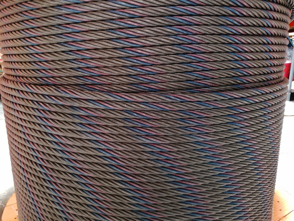
When choosing or designing a custom wire rope for your application, suppliers consider factors such as: the environment in which the rope will function, required rust resistance, required flexibility, temperature resistance, required breaking strength and wire rope diameter. To accommodate your needs, manufacturers can do special things like: make your rope rotation resistant, color code your rope, or add a corrosion resistant coating. For instance, sometimes they specially treat and coat a cable with plastic or some other compound for added protection. This is particularly important to prevent fraying if the wire rope is often in motion on a pulley.
Manufacturers and distributors identify the differences in wire cable by listing the number of strands and the amount of wires per strand so that anyone that orders understand the strength of the cable. Sometimes they are also categorized by their length or pitch. Common examples of this include: 6 x 19, 6 x 25, 19 x 7, 7 x 19, 7 x 7, 6 x 26 and 6 x 36.
More complex wire rope identification codes connote information like core type, weight limit and more. Any additional hardware like connectors, fasteners, pulleys and fittings are usually listed in the same area to show varying strengths and degrees of fray prevention.
Cable wire rope is a heavy-duty wire rope. To give it its high strength, manufacturers construct it using several individual filaments that are twisted in strands and helically wrapped around the core. A very common example of cable wire rope is steel cable.
Spiral rope is made up an assemblage of wires with round or curved strands. The assemblage features at least one outer layer cord pointed in the opposite direction of the wire. The big advantage of spiral ropes is the fact that they block moisture, water and pollutants from entering the interior of the rope.
Similarly, stranded rope steel wire is made up of an assemblage of spirally wound strands. Unlike spiral rope, though, its wire patterns have crisscrossing layers. These layers create an exceptionally strong rope. Stranded rope may have one of three core material types: wire rope, wire strand or fiber.
Wire rope chain, like all chains, is made up of a series of links. Because it is not solid, wire rope chain is quite flexible. At the same time, it is prone to mechanical failure.
Wire rope slings are made from improved plow wire steel, a strong steel wire that offers superior return loop slings and better security. The plow wire steel also shields rope at its connection points, which extends its working life. Wire rope slings, in general, provide their applications with increased safety, capacity and performance. Wire rope sling is a rope category that encompasses a wide range of sub-products, such as permaloc rope sling, permaloc bridle slings and endless slings. These and other wire rope slings may be accompanied by a wide variety of sling terminations, such as thimbles, chokers and hooks.
Wire rope offers its user many advantages. First, design of even distribution of weight among strands makes it ideal for lifting extremely heavy loads. Second, wire rope is extremely durable and, when matched properly to the application, can withstand great stress and elements like corrosion and abrasion. In addition, it is very versatile. Its many iterations and the ways in which the rope can treated means that users can get rope custom fit for virtually any application.
Depending on the type of wire rope with which you are working and your application, you may want to invest in different accessories. Among these accessories are: wire rope clips, steel carabiners, fittings, fasteners and connections.
To ensure that your wire rope quality remains high, you must regularly inspect them for wear and degradation. The right wire rope should be selected for a particular use. Watch out for performance-impacting damage like: rust, fraying and kinks. To make sure that they stay in tip-top shape, you should also clean and lubricate them as needed. Check for this need as a part of your regular inspection.
Rope care is about more than inspection. It’s also about making an effort to use and store them properly every time you use them. For example, never exceed your rope’s rated load and breaking strength. Doing so will not only cause the weakening of your cable, but it may even cause immediate breakage. In addition, always store your wire rope cable in a dry and warm area, away from those elements that could cause premature rusting or other damage. Finally, always carefully wind your wire rope when you’re done with it, so as to avoid kinks. If you follow all these tips and treat your wire rope assemblies well, they will reward you with a long and productive service life.
Always make sure that you purchase wire rope that matches your industry and regional standards. Some of the most widely referenced standards organizations for wire rope include: ISO, ASTM International and OSHA. Talk over your specifications and application with your wire rope supplier to figure out what’s best for you.
If you’re in the market for a wire rope or a wire rope assembly, the best way to know you’re getting something that will both perform well and be safe if by working with a vetted professional. Find one among the list we’ve provided on this page. Check out their profiles to get an idea of the services and products they offer. Pick out three or four to whom you’d like to speak, and reach out. Talk to them about your specifications, standard requirements and budget. Ask about lead times and delivery options. Once you’ve spoken with all of them, compare and contrast their answers. You’ll know you’ve found the one when you talk to a wire rope company that is willing to go above and beyond for your satisfaction.

CLEVELAND, OH – Mazzella Lifting Technologies, a Mazzella Company, is pleased to announce the acquisition of Denver Wire Rope & Supply. This acquisition will strengthen Mazzella’s footprint west of the Mississippi River and reinforce Mazzella’s commitment to be a one-stop resource for lifting and rigging services and solutions.
Denver Wire Rope & Supply has been in business since 1983 and services a variety of industries out of their location in Denver, CO. Denver Wire Rope & Supply is a leading supplier of rigging products, crane and hoist service, below-the-hook lifting devices, and certified rigging inspection and training. Effective immediately, Denver Wire Rope & Supply will operate as Mazzella / Denver Wire Rope. Terms of the transaction are not being disclosed.
“Denver Wire Rope & Supply will complement the wide range of products and services that Mazzella Companies offers. We are dedicated to being a single-source provider for rigging products, overhead cranes, rigging inspections, and rigging training. Both companies commit to a customer-first mentality, providing the highest-quality products, and leading by example when it comes to safety and sharing our expertise with customers and the market,” says Tony Mazzella, CEO of Mazzella Companies.
“Our team and family are excited to be part of the Mazzella Companies. This acquisition strengthens our place in the market and allows our team to continue to provide excellent service and products to our valued customer base and expand our offering,” says Ken Gubanich, President of Denver Wire Rope & Supply.
“Over the years, we have had numerous companies show interest in purchasing Denver Wire Rope & Supply, none seemed to be the right fit. We are looking forward to becoming a part of an aggressive, passionate, and progressive organization. As a family business for over 36 years, it is important to us that our customers/friends, suppliers, and team members continue to be treated with first-class service, products, and employment opportunities. Again, we are very enthusiastic about our future and look forward to being a quality supplier for your crane, safety training, rigging, and hoisting needs for years to come,” says Gubanich.
“We wish Ed and Carol Gubanich all the best in their retirement. We welcome Ken and the other second and third-generation Gubanich family members, as well as the entire Denver Wire Rope Team, into the Mazzella organization,” says Mazzella.
We’ve changed our name from Denver Wire Rope to Mazzella. Aside from the new name and logo, our member experience is virtually unchanged. Here are some common questions and answers related to this change.
In 2019, Denver Wire Rope & Supply was acquired by Mazzella Companies to expand lifting and rigging products and services to the western half of the United States.
In 1954, James Mazzella founded Mazzella Wire Rope & Sling Co. in Cleveland, OH. For over 65 years, the company has grown organically by nurturing historic relationships, expanding its product offerings, and entering new markets through acquisition.

Wire rope is a complex mechanical device that has many moving parts all working in tandem to help support and move an object or load. Wire ropes are attached to a crane or hoist and are fitted with swivels, shackles or hooks. These are suitable for lifting or lowering elevators and are also used for supporting suspension bridges or towers.
In this article, we"ll cover details on the top U.S. providers of wire ropes, along with our featured list of top wire rope suppliers on Thomasnet.com.
Below is a list of featured suppliers of wire rope from our platform. Included with these companies is their location, year established and the number of employees.
Below we have assembled information on the top suppliers of wire rope in the U.S. based on currently available public sales data. The table also includes the company name, location and the number of employees.
With the help of the provided details on the wire rope suppliers in the United States in the above tables and descriptions, we hope you can use this data to further aid your sourcing decisions.
Wire ropes are largely used in marine environment or for rigging purposes. They receive considerable loads and thus suffer a great deal of mechanical damage throughout their service life. Moreover, research has shown that the major cause of wire rope failure is excessive deterioration and corrosion, lack of maintenance and inspection, and wrong usage resulting in early discarding, reduced safety and replacement cost increase.
Sometimes damage can be easily detected, while in other cases fractured wires may occur on the inside. Hence, wire ropes should be inspected and maintained by the right person (competent person assigned by the company), to assure they’re in perfect condition. Regular inspectionsensure high rope performance, long service lifetime , safety of personnel and equipment, and reduced operating costs.
All ropes (synthetic, high modulus and wire ropes) should be inspected before and after an operation. This guideline ensures maximum safety for both a ship’s personnel and equipment. Even though it’s difficult to determine the exact service life span of ropes, there is a way to have a more precise estimation about their efficient lifecycle. Calculating the exact time ropes have been in use (e.g mooring time, mooring conditions, weather and tidal conditions) is the answer. All in all, rope inspections should occur at least once a year.
Inspecting wire ropes in particular, comes with great responsibility. Inspection results should be recorded, and any defects noticed have to be reported and addressed properly. Some defects can be repaired, while in some cases replacing a wire rope is inevitable.
Periodical inspections ofvessel deck equipment is also crucial for maintaining the good condition of wire ropes. The condition of the drum, chocks, bitts, rollers, sheaves, cable clamps and other end fittings, affect the rope’s performance, threads and cords. Make sure to mark these parts during your overall inspection.
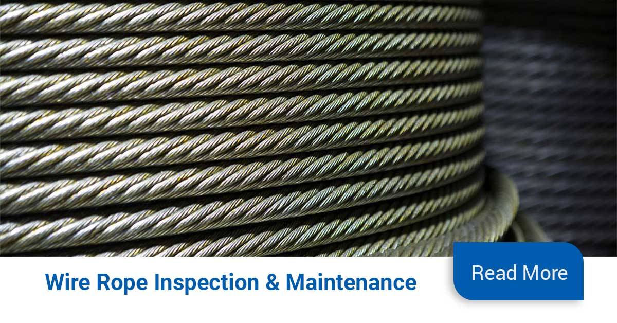
In order to help marine officers and staff conduct successful wire rope inspections – and keep an up-to-date record of them – we have created an inspection solution that helps in maintaining and monitoring a ship’s ropes and deck equipment.
When calculating mass using F = Minimum Breaking Force, according to the wire rope’s diameter, you can determine the Minimum Breaking Massand therefore the wire’s max strength. When calculating mass using F = Safe Load according to the wire rope’s diameter, you can determine the Safe Load Mass,which is the advised load for this rope diameter.
The strands of a wire rope absorb the majority of the tensile force applied on the rope. Their design and manufacturing standards affect the level of fatigue resistance and resistance to abrasion. An easy way to understand which rope design is suitable for each purpose, is the wire rope classification.
Wire ropes are classified according to the number of strands in each construction and the number of wires in each strand. For example, a classification of 6X19 means that a wire rope of this type always has six strands, but its wires could be 15-26 per strand. This is because 19 is not the exact number of wires, but the classification of a wire number range.
Visual inspections are a common and fast way to assess wire rope condition. Both the standard and rotation resistant wire rope inspectionprocesscomply with the same four steps of examination. A ship’s crew can perform them as follows:
Steel wire rope distortion is obvious in most cases and can easily be identified by the inspector or the ship‘s crew. It usually occurs if load is suddenly applied or abruptly released (shock loading), or even if swift torque is forcefully induced.
Although not all of these deformations make the rope absolutely dangerous to use, they all may cause ropes to wear unevenly in time. This means inspections should take place more often, and distorted ropes should be handled with caution.
The rag and visual inspection is a good method for regular inspection intervals. The inspector pulls a rag along the rope trying to find broken wire cords. If the rug gets snagged by the rope, the inspector has to stop and assess the wire rope’s condition. Extreme caution should be exercised during the visual inspection, and under no circumstances should this method be the only one used to inspect wire ropes.
Tip: When you encounter a protruding wire end, bend it back and forth manually, until it separates from the wire. This will protect neighboring wires from wearing out.
Diameter reduction is a critical factor in steel wire rope wear and if not properly taken care of, it can result in rope breakage. Excessive abrasion, loss of core mass, corrosion or inner wire failure are all factors that contribute to diameter reduction.
To get an accurate measurement of the rope’s diameter, measure the rope at three different points at least 5 feet apart. Take the average of these three measurements to determine the true diameter.
Any measurements showing a reduction of ⅓ or more, indicate that a replacement should follow without delay. A diameter reduction of less than 1/3 still requires attention, and the inspector or the ship’s crew should be on guard in the next scheduled wire rope inspection.
Failure from abrasion or corrosion is a result of deficient deck equipment inspection or insufficient wire rope lubrication respectively. Internal corrosive damage is more difficult to identify than any other types of degradation. In most cases, the damage has progressed more than the external signs suggest.
Wire rope storage plays a significant role in the rope’s operation life.Wire rope corrosion and pitting can be avoided if ropes are safely stored in a clean, cool, dry and well-ventilated place. Steel wire ropes should not by any means rest on the floor, and should be protected from water, dust or any chemical fumes. Long term storage requires periodic greasing, turning the reel upside down for preventing grease dripping and possibly re-winding to another reel with larger inner tube diameter.
Wire ropes should be maintained with periodical lubrication. In order to prevent internal corrosion, a pressure lubricator is suggested to be used. In this case, a small amount of grease is used to lubricate the rope internally, while the deck stays grease-clean. Pressure lubricators clean the rope before they grease it so that the new grease enters a clean rope. The type of grease used is very important for maximum protection and greasing efficiency.
Steel wire ropes exposed to dirt, grime and other contaminants, have to be cleaned with a wire brush and petroleum (unless a pressure lubricator is used). Optimal cleaning of wire ropes can extend their service life and guarantee safe operations.
The reeling process is of high importance for the longevity of wire ropes. To protect them from being damaged, it is important that the surface of the drum is clean, smooth and dry. Improper reeling may cause wire-rope strands to spread or get flattened, when in contact with one another, as successive layers are being spooled and upper layers apply pressure on the lower ones.
Katradis S.A. offers a wide range of top quality wire ropes for shipping (mooring and hoisting operations), fishing and construction purposes. Our wire ropes have greater resistance to fatigue, and they distribute tension force equally among the rope strands. They are less likely to kink, providing higher staff safety and assuring operation success.
Abrasion damage may occur when the rope contacts an abrasive medium or simply when it passes over the drum and sheaves. Therefore it is vital that all components be in proper working order and of the appropriate diameter for the rope. A badly corrugated or worn sheave or drum will seriously damage a new rope, resulting in premature rope replacement.
Corrosion is very difficult to evaluate but is a more serious cause of degradation than abrasion. Usually signifying a lack of lubrication, corrosion will often occur internally before there is any visible external evidence on the rope’s surface. A slight discoloration caused by rusting usually indicates a need for lubrication which should be tended to immediately. If this condition persists, it will lead to severe corrosion which promotes premature fatigue failures in the wires and strands, necessitating the rope’s immediate removal from service.
The table below shows the number of allowable wire breaks per crane type. The inspector must know the ASME standard for the equipment being inspected. The number of broken wires on the outside of the wire rope is an indication of its general condition and whether or not it must be considered for replacement. The inspector may use a type of spike to gently probe the strands for any wire breaks that do not protrude. Check as the rope runs at a slow speed over the sheaves, where crown (surface) wire breaks may be easier to see. Also examine the rope near the end connections. Keeping a detailed inspection record of the wire breaks and other types of damage will help the inspector determine the elapsed time between breaks. Note the area of the breaks and carefully inspect these areas in the future. Replace the rope when the wire breaks reach the total number allowable by ASME or other applicable specifications.
Valley breaks, or breaks in between strands, must be taken very seriously at all times!When two or more valley breaks are found in one lay-length, immediately replace the rope. Valley breaks are difficult to see; however, if you see one you can be assured that there are a few more hidden in the same area. Crown breaks are signs of normal deterioration, but valley breaks indicate an abnormal condition such as fatigue or breakage of other wires such as those in the core.
Once crown and valley breaks appear, their number will steadily and quickly increase as time goes on. The broken wires should be removed as soon as possible by bending the broken ends back and forth with a pair of pliers. In this way the wire is more likely to break inside the rope where the ends will be tucked away. If the broken wires are not removed they may cause further damage. The inspector must obey the broken wire standard; pushing the rope for more life will create a dangerous situation.
It is important to check and record a new rope’s actual diameter when under normal load conditions. During the life of the rope the inspector should periodically measure the actual diameter of the rope at the same location under equivalent loading conditions. If followed carefully, this procedure reveals a common rope characteristic—after an initial reduction, the overall diameter will stabilize and slowly decrease in diameter during the course of the rope’s life. This condition is normal. However, if diameter reduction is isolated to one area or happens quickly, the inspector must immediately determine (and correct, if necessary) the cause of the diameter loss, and schedule the rope for replacement.
Crushing or flattening of the strands can be caused by a number of different factors. These problems usually occur on multilayer spooling conditions but can occur by simply using the wrong wire rope construction. Most premature crushing and/or flattening conditions occur because of improper installation of the wire rope. In many cases failure to obtain a very tight first layer (the foundation) will cause loose or “gappy” conditions in the wire rope which will cause rapid deterioration. Failure to properly break-in the new rope, or worse, to have no break-in procedure at all, will cause similar poor spooling conditions. Therefore, it is imperative that the inspector knows how to inspect the wire rope as well as how that rope was installed.
Shock loading (bird-caging) of the rope is another reason for replacement of the rope. Shock loading is caused by the sudden release of tension on the wire rope and its resultant rebound from being overloaded. The damage that occurs can never be corrected and the rope must be replaced.
High stranding may occur for a number of reasons such as failure to properly seize the rope prior to installation or maintain seizing during wedge socket installation. Sometimes wavy rope occurs due to kinks or a very tight grooving problem. Another possibility is simply introducing torque or twist into a new rope during poor installation procedures. This condition requires the inspector to evaluate the continued use of the rope or increase the frequency of inspection.
It is a handsome bridge. Its functionality and aesthetics, by design, are commendable. This bridge is important to the vitality of the greater seacoast area. However, we should be thankful that the Portsmouth Herald has chosen to reveal, for the public benefit, that the long-awaited new Sarah Mildred Long Bridge has a “wavy rope” problem. This problem may be but one of a long litany of problems related to the design and construction of this bridge.
On behalf of those who will be using and paying for many years to come, it is important that this problem be properly addressed by the Maine DOT and their partner NHDOT, along with the designers and builders of the bridge.
For the uninitiated, I will avoid a detailed dissertation, and I will not get too technical. However, there may be some confusion here. There is no common “rope” in this bridge. What we have is wire rope or steel cable. The “wavy-rope,” is not a rope at all. Wavy-rope is a euphemism for one of the characteristics of flawed steel cable. The primary structural elements in the carrying of the large forces that are exerted in the lifting, lowering, and resting of the large movable center section of the bridge in its normal day-to-day operations, is a set of structural steel cables.
These structural cables are made up of multiple high-strength steel wires combined in a rigorously-controlled manufacturing process. Normally, the wires and the cables are carefully designed, manufactured, installed, inspected, and engaged in the normal operation of such a lift bridge. The cables, so-called, are each a combination of strands, each of which is a combination of a uniquely designed array of wires. These bundles of wires/strands/cables are the primary load-carrying structural elements that carry the dead weight and the live loads on the movable section. The proper composition of wires, strands, and cables results in the proper supporting system that is strong enough, stiff enough, and flexible enough to carry the required loads day-in and day-out over long periods of time, presuming they exist as designed.
But, things do not always go as designed. A “wavy rope” is a structural steel cable that has one or more defects or flaws, structural flaws, which likely diminish the structural integrity, structural longevity, and operationality. A flawed steel cable often exhibits the symptoms of those defects, as in the “wavy rope.” Waviness, or a lack of straightness, can be the consequence of, for example, material defects in the metallurgy of the steel, the improper fabrication or handling of the wires, the improper fabrication or handling of the strands, the improper fabrication or handling of the cables, bends or kinks in the wires or strands, broken wires, missing wires, frays, twists, corrosion, improper spooling and unspooling, improper installation and operation. These flaws, one or more, may be due to failings in the design, metallurgy, manufacturing processes, handling and installation, and/or operation.
Material and structural properties, and the resulting structural integrity are compromised by the existence of structural flaws. The useful life or longevity of such a cable is compromised or shortened. Using wavy cable in the mechanical cable-handling lifting systems, which include guides, sheaves, and pulleys, which may have dimensions incompatible with the cable dimensions which, in turn, may be changing and wearing by damaging frictional forces as it plays through the incompatible mechanical constraints.
Wire Rope is an item often found on Wire Rope Cranes. Unfortunately, though these wires are not unbreakable and can/will succumb to the pressure of constant use and may potentially snap when in use. Which is why it is important to know what to look out for in an unsafe wire rope, the Government of Canada recommends a visual inspection of the wire before each use, but full inspections should be undertaken by a trained professional periodically. This article will cover what causes wire ropes to break, what your professional inspector will do to ensure your rope is safe and what you can look out for when completing your frequent inspection to ensure the rope is safe to work with.
When you hear the term wire rope you may picture in your mind a metal and seemingly unbreakable rope, and through wire ropes, can and will stand up better than many other rope types it is unfortunately not unbreakable. Some things that can cause a wire rope to break include:
Kinks caused by improper installation of a rope, sudden release of a load or knots that were made to shorten a rope can cause the rope to become compromised
Many of these causes can be minimized by the use of proper crane design and rope maintenance procedures, most of these causes though are unavoidable and are considered to be part of a normal rope life. The two main causes that are considered unavoidable are crushing and internal and external fatigue.
Many wire ropes are subject to a lot of repetitive bending over a sheave, which causes the wire to develop cracks in its individual wires. These broken wires often develop in the sections that move over sheaves. This process will become escalated if a rope travels on and off of a grooved single layer drum, which causes this to go through a bending cycle. Tests in the past have shown that winding on a single layer drum is equal to bending over a sheave because it causes similar damage.
Fatigue breaks often develop in segments as stated before these segments are usually the part of the rope surface that comes into direct contact with a sheave or drum. Because this is caused by external elements rubbing, oftentimes these breakages are external and visible for the eye to see. Once broken wires start to appear, it creates a domino effect and quickly much more will appear. Square ends of wires are common for fatigue breaks. These breaks are considered a long-term condition and are to be considered part of the normal to the operating process.
Internal Breaks,these breaks can develop over time-based upon the loading of the hoist. Many ropes are made of a torque-balanced multi-strand design, which comprises of two or more layers of strands. A torque balance is created in multi-strand ropes, by layering the outside and inside ropes in opposite directions. Multi-strand ropes offer much more flexibility and have a more wear-resistant profile. Though the wires in these ropes touch locally and at an angle, which causes them to be subject to both the effect of radial load, relative motion between wires and bending stresses when bent on sheaves or drums.
Nicking and fatigue patterns such as the ones discussed before occur in Independent Wire Rope Cores or IWRC ropes. IWRC ropes have outer wires of the outer strands, which have a larger diameter than the outer core strands. This helps to minimize inner strand nicking between the outer strands of the IWRC. The outer strands and the IWRC strands are approximately parallel. Often their neighbouring strands support these outer strands while the outer IWRC wires are relatively unsupported.
With these geometrical features it allows for the wire to fluctuate under tensile loads, the outer IWRC wires are continuously forced into valleys in between the outer strand wires and then released. This system results in secondary bending stresses which leads to a large number of core wires with fatigue breaks. These breaks are often close together and form in groups. This eventually leads to the IWRC breaking or completely disintegrating into short pieces of wire that lay, half a length long. This condition is often called complete rope core failure.
It is as the IWRC fails, and the outer strands lose their radial support then valley breaksform. Valley breaks occur when the outer strand wires bear against each other tangentially. This results in interstrand nicking, which restricts the movement of strands within the rope; without the freedom to move, secondary fatigue breaks occur in the outer strands, which will develop a stand tangent points. These breaks occur in the valleys between the outer strands hence why they are called valley breaks.
So to go over what we just learned, internal broken wires occur often in ropes that are operated with large diameter sheaves and high factors of safety. These breakages can occur when a reeving system incorporates sheaves lined with plastic or all plastic sheaves; these sheave units offer more elastic support than their steel counterparts. Which causes the pressure between outer wires and sheave grooves to be reduced to the point where the first wire breaks will occur internally.
If a section of a rope travels on and off of a grooved multi-layer drum, then it goes through what is called a bending cycle. The bending cycle occurs by a section of rope spooling in the first layer and is bent around the smooth drum surface, but when the second layer rolls around the rope section in the first layer will be spooled over. This causes the first layer to become compressed and damaged on the upper side by the second rope layer. With continued spooling the rope layers in the second and higher layers will, in turn, be damaged on both sides during contact with their neighbouring rope layers. This damage is caused both by the compression of the rope and by the rope laying on a rough surface.
Accelerated wear occurs where the point of the rope is squeezed between the drum flange and the previous layer. Often times the slap of rope at the crossover points causes peening, martensitic embrittlement and/or wire plucking, further associated rope damage is caused when the rope crosses over from layer to layer on a drum.
Also, if the lower wire rope areas where not spooled under sufficiently high tension the lower wraps can become displaced by the additional rope sections which would allow for these new rope sections to slide down in between them, which will lead to severe rope damage.
Many regulators have decided that the Statutory Life Policy be overly wasteful and they tend to use the Retirement for Clause Policy. A wire rope deteriorates slowly over its entire service, but to be aware of the state of deterioration, a wire rope must be periodically inspected. Moderate deterioration is normally present, and low levels of deterioration do not justify retirement. Which is why you have wire rope inspections to monitor the normal process of deterioration. This ensures that the rope can be retired before it can become dangerous. Besides, these inspections can detect unexpected damage or corrosion on the wire rope which will allow you to take corrective actions to ensure the longevity of the wire rope.
This system is useful for detecting external rope deterioration. To use this approach, the inspector will lightly grab the rope with a rag. The inspector then glides the cloth over the rope. Often times external broken wires will porcupine (stick up). When the rope moves along the wire it will be snagged on the broken wire. The inspectorwill then stops dragging the cloth along the wire and visually inspects the condition of the wire.
Frequently broken wires often do no porcupine, which is why a different test procedure must be utilized. This test involves moving along the rope two or three feet at a time and visually examining the rope. This method though can become tiresome because oftentimes the rope is covered in grease and many internal and external defects will avoid detection through this method.
Another method involves measuring the wire ropes diameter. This involves comparing the diameter of the current rope to the original rope’s diameter. Changes in the diameter of the rope indicate external and/or internal rope damage. This method is not perfect because many different wire breakages damages do not change the diameter of the rope.
You can also check for several visible signs of distributed losses of the metallic cross-sectional area. This is often caused by corrosion, abrasion and wear. To internally check for damage, you can insert a marlinspike under two strands and rotate it to lift the strands and open the rope.
Visual inspections are often not well suited for the detection of internal rope damage. This means that they have limited value as the only means of wire rope inspection. Though visual inspections do not require special machines. When completed by a knowledgeable and experienced rope examiner through visual inspections can be valuable tools for evaluating rope degeneration.
Electromagnetic Inspections or EM gives a detailed insight into the exact condition of a rope. EM is a very reliable inspection method and is a universally accepted method for inspecting wire ropes for mining, ski lifts and other similar industries. There are two distinct EM inspection methods, which have been developed to classify defects called Localized-Flaw (LF Inspection) and Loss-of-Metallic-Area Inspection (LMA Inspection type)
LF Inspection is similar to the rag-and-visual method. This inspection method is suited primarily for finding localized flaws, such as broken wires. Which is why small hand-held LF instruments are called electronic rags.
Electromagnetic and visual wire rope inspection methods are like peanut butter and jelly or cookies and milk they are the perfect combination, and both are essential for safe rope operation. Which is why both methods are often used to ensure maximum safety.
A program that involves periodic inspections is extremely effective. To establish baseline data for future inspections, a wire rope inspection program should begin with an initial inspection after a break-in period. Then the inspections should follow at scheduled intervals, with documentation of the ropes deterioration over its entire service life.
For multi-strand ropes often times visual inspections are ineffective which is why statutory life policy for a ropes retirement is often adopted. This means that these ropes are often discarded long before they should be meaning millions of dollars’ worth of perfectly good wire ropes are being thrown away annually.
Some people have suggested that non-rotating ropes should not be used if cranes use a single layer winding on a drum. Following this line of thought, this would mean multi-strand ropes should be used only when winding on multi-layer drums. This would cause wires to break the surface faster than internal wire damage can occur, these non-rotating wire ropes will be replaced long before internal fatigue can set in.
When internal broken wires are the problem electromagnetic rope testing can be the solution. Though there are some factors one needs to take into account such as certain regulations require rope retirement when a certain number of broken wires per unit of rope length exceed a set limit. This discard number that is specified in retirement standards refers solely to external wire breaks. This means the condition of a wire rope with internal breaks is therefore left up to the inspector.
Though you also need to take into account detailed detection and quantitative characterization of internal broken wires in ropes with many breaks and cluster breaks could be a problem. These difficulties are caused by the fact that electromagnetic wire rope can be influenced by several parameters such as:
Clusters of broken wires can cause an additional problem because the relative position of broken wires concerning each other within the rope is not known
Broken wires with zero or tight gap widths are not detectable by electromagnetic inspection because they do not have a sufficient magnetic leakage flux.
When you consider all of this you can quickly realize that you can only estimate the number of broken wires that have formed on a wire rope. You can use the LF trace for the detection of broken wires, though unfortunately it is not quantitative so it cannot be used to estimate the number of broken wires. Though it is good to note that if any internal broken wires are present an LMA trace will show rapid relatively small variations of a cross-section.
An electromagnetic inspection will help to enhance the accuracy and reliability of the inspection, by combining visual and EM methods they will be able to detect deterioration at the earliest stages. The inspections can be then used as an effective preventive maintenance tool. For example, the inspector early on detects corrosion, and you immediately apply the corrective action of improving the lubrication of the wire rope.
Wire ropes should be inspected by a certified inspector when installing it, and periodically throughout its life cycle. A wire rope should go through a quick, but thorough inspection every day that you use it at the beginning and end of each shift and you should keep records of all inspections. Ensure that your certified wire rope inspector uses a combination of visual inspection methods and electromagnetic inspection methods because this will ensure the optimum safety and longevity of the rope. This is especially true for ropes that are more likely to develop internal broken wires, and inspections completed by a certified inspector is the best way of having a preventive maintenance program and extending the life of your wire rope.
Queensland Division of Workplace Health and Safety, “Non-rotating hoist wire ropes, multi fall configurations, Health and Safety Alert,” http://www.whs.qld.gov.au/alerts/97-i-5.pdf
Verreet, R. “Wire rope damage due to bending fatigue and drum crushing,” O.I.P.E.E.C.(International Organization for the Study of the Endurance of Wire Rope) Bulletin 85, June 2003, Reading (UK), ODN 0738, pp. 27-46.
The lifetime of wire rope is crucial in industry manufacturing, mining, and so on. The damage can be detected by using appropriate nondestructive testing techniques or destructive tests by cutting the part. For broken wires classification problems, this work is aimed at improving the recognition accuracy. Facing the defects at the exterior of the rope, a novel method for recognition of broken wires is firstly developed based on magnetic and infrared information fusion. A denoising method, which is adopted for magnetic signal, is proposed for eliminating baseline signal and wave strand. An image segmentation method is employed for parting the defects of infrared images. Characteristic vectors are extracted from magnetic images and infrared images, then kernel extreme learning machine network is applied to implement recognition of broken wires. Experimental results show that the denoising method and image segmentation are effective and the information fusion can improve the classification accuracy, which can provide useful information for estimating the residual lifetime of wire rope.
Wire ropes play an important role in many fields such as cranes, oil drilling rigs, elevators, and mine hoist. The safety of wire ropes is closely related to people’s life and resources loss as well as the normal operation of industry. Because of the complex structure of wire ropes and the diversity of application environment, it is difficult to evaluate the health of wire ropes in service [1, 2]. Thus, it is necessary to effectively and accurately perform the quantitative nondestructive testing (NDT) of wire rope by adopting proper methods.
At present, the NDT methods of wire rope include electromagnetic [3, 4], X-ray [5], acoustic [6–9], and optical [10] method [1]. X-ray apparatus has radioactive contamination; acoustic method detects wire rope by striking, which is simple but one-sided; CCD camera optical testing method can directly show the real defects through imaging, but it is susceptible to oil pollution; because of high sensitivity, high speed, and low cost, electromagnetic NDT method is widely used [11–14]. However, no single nondestructive testing technique can identify all kinds of defects. Infrared nondestructive testing does not contain dangerous radiation and has characteristic of noncontact; thus, it has widely applied in solving real problems in numerous areas [15].In addition, its popular application areas contain building sector [16, 17], aeronautics and astronautics [18], chemical industry [19], food [20], cultural heritage [21], and so on. Munoz et al. [22, 23] determined heat source dissipation from infrared thermographic measurements based on the heat diffusion equation provided by thermodynamics principles and identified damage evolution in carbon fibre reinforced composites combing acoustic emission and infrared thermography.
Magnetic flux leakage (MFL) detection of wire rope mainly includes the forward calculation model of MFL detection, pretreatment of MFL signal, and inversion of defect [24]. For example, Yan et al. [25] employed a three-dimensional finite element method (FEM) to analyze MFL signals. This method provided theoretical guidance for detection signal analysis and hardware design. Based on the magnetic dipole model, Yang [2] created the leakage magnetic field analysis models of single wire fracture, surface broken wire, and internal broken wire of wire rope, which provided the theoretical basis for the quantitative analysis of wire rope. Zhao and Zhang [11, 12] made FEM on the distribution of magnetic flux leakage of typical broken wire defects in steel cables, and obtained the relationship between MFL and detection distance, damage size, and internal broken wire. In [13, 14], a magnetic dipole model was established to design the prototype, which provided a theoretical basis for the quantification of defects. Through the FEM model of wire rope and the FEM simulation under different broken wires, DU et al. [26] studied the influence of different broken wires on the safety coefficient of wire rope.
Because actual MFL detection signals are polluted by many noise sources, it is necessary to preprocess the signals in order to reconstruct the defects. Zhang et al. [27, 28] utilized wavelet based on compressed sensing to denoise the strand wave, but it restored a lot of noise; then, they combined the Hilbert-Huang Transform (HHT) and Compressed Sensing Wavelet Filtering (CSWF) to reduce various background noises. Zheng and Zhang [29] exploited wavelet soft threshold to inhibit the noise; nevertheless, the denoising effect is poor. Then Zheng and Zhang [30] implemented Variational Mode Decomposition (VMD) and a wavelet transformation to remove noise from the raw MFL signals, which can effectively eliminate noise. Hong et al. [31] proposed an adaptive wavelet threshold denoising method based on a new threshold function, which achieved good denoising effect on the MFL signal of wire rope. To realize the visualization of defects, Zhao [13] utilized an adaptive notch filtering algorithm for suppressing wave noise.
To visualize and quantify defects and realize quantitative detection of broken wires, researchers need to implement defect inversion. In order to perform defect inversion, numerous scholars have used various methods. Through adopting the wavelet super-resolution reconstruction technique, the resolution of defect grayscale was improved in [32]. Zhang and Tan [33] proposed a super-resolution (SR) reconstruction method based on Tikhonov regular multiframe, which can effectively remain image features of defects while the axial resolution was reduced and circumferential resolution was increased. In [28, 32], researchers implemented classification of defects by adopting back propagation (BP) neural networks. However, BP was easy to fall into local minimum, which can lead to problems such as network underfitting and insufficient generalization ability. Wan et al. [34] investigated the theory on optimal wavelet packet with the Least Squares Support Vector Machine (LS-SVM) to diagnose elevator faults, which was then validated by the experiment. Zheng and Zhang and Qin et al. [29, 35] took the Support Vector Machine (SVM) with a radial basis function classified to conduct the fault pattern recognition, whereas this method was not very effective.
The researchers [15, 36] investigated the failures of steel ropes and defect of ferromagnetic specimens by means of thermovision. In [15], since the measurements required extremely sensitive thermovision technology, the method can detect the tight of ropes at certain conditions. In [34], the researchers developed a new active thermography technique, which can detect the defect in ferromagnetic steel specimens. The fusion of infrared and other information is effective and widely used. Kee and Oh et al. [16] combined air-coupled impact-echo and infrared thermography. It can improve effectiveness of the individual test data. Data fusion of ground-penetrating radar and infrared thermography improved the accuracy of detecting defects [37]. The researchers [38] combined finite element analysis with experimental data from infrared thermography, which provided accurate means to assess quantitatively the size and position of thermal imperfections. According to these, it is demonstrated that data fusion is effective. In this paper, fused data based on infrared thermography and magnetic is utilized to detect the number of broken wires.
Electromagnetic NDT for wire rope is susceptible to hardware design and magnetic signal processing. In [13, 14], the location and number of sensors can affect the quality of acquisition signal. Insufficient quantity will lead to the serious loss of MFL signal, while dense placement of sensors can lead to serious signal interference, resulting in difficulty of noise reduction. Meanwhile, the small broken wire defect information may be drowned out by noise. However, thermal infrared is a visualization method, which can intuitively grasp the surface damage state of wire rope and be closer to the actual damage pattern than magnetic data. Meanwhile, it is without the shortcomings of magnetic detection method and it can make up for the loss of small defects in magnetic information. Thus, the combination of the two methods supply more information for the damage and can avoid the loss of defect information.
To improve classification accuracy of broken wires and provide a reference for evaluating the service life of wire rope, the combination of infrared information and magnetic information is put forward for the first time to perform quantitative identification of wire rope. To processing magnetic signal, an algorithm based on Wavelet Total Variation (WATV) is proposed to remove noise from the raw MFL signals. The noise from high-frequency magnetic leakage, baseline drift, and strand waves can be suppressed by the proposed algorithm. To separate defects from infrared images, an image processing method based on distance is presented. After extracting statistical texture, invariant moment characteristics, and color moment, a fusion method based on kernel extreme learning machine (KELM) of decision level fusion is proposed to combine magnetic and infrared information. Experiment results show that the information fusion based on magnetic and infrared can improve the recognition rate of broken wires.
In the next sections, the platform to get data, the processing for magnetic data, steps for extracting infrared information, and recognition for broken wires after information fusion will be introduced in turn. In this paper, major innovations are as follows: (1) the proposed denoising algorithm based on WATV can eliminate noise generated by channel imbalance, the structure of wire ropes, and so on; (2) an infrared image segmentation algorithm based on distance is presented; and (3) information fusion combined magnetic with infrared to perform classification is firstly adopted.
In this part, through processing and fusing magnetic signal and infrared image, the classification for six kinds of broken wires is implemented. In this experiment, the number of broken wires is one, two, three, four, five, and seven. Many wires are wound into a strand, then it is wounded into a wire rope. The damage of the wire rope is related to the geometry and winding mode of the wire rope [1, 2, 13]. As shown in Figure 1, the structure of the wire rope is with a diameter of 28 mm. The length of the wire ropes is 6.5 m. The specimens used are 185, where the number of training samples is 139 and testing number is 46. The number of broken wires is from 1 to 5 and 7 wires, where the number of every samples set of broken wires is 30, 30, 32, 34, 35, and 34. The width of samples contains 2 mm, 5 mm, and 1.5 cm. The depth of defects is 1 mm. The type of defect is shown in Figure 2.
When there is no defect on wire rope and materials of the wire rope are uniform and identical, the magnetic flux through the cross-section of the wire rope should be equal in the axial direction. If there is a defect, the permeability at the defect becomes smaller, the magnetic field only passes through the air field and then returns to the inside of the wire rope; thus, magnetic leakage on surface is formed [12–14]. According to this principle, a magnetic flux leakage detection device is designed. Data collection contains magnetic signal acquisition and thermal infrared image acquisition. The specific devices and collecting procedures are as follows: the magnetic data acquisition device adopted contains Unsaturated Magnetic Excitation (UME) source, an array of 18 Giant Magnetoresistance (GMR) sensors, data acquisition unit, data storage, and control system [33].
As shown in Figure 4, data collection steps are as follows: After loading unsaturated magnetic field on wire rope, the weak MFL signal can be obtained through equal-space sampling. As the acquisition system moves along the axial direction of the wire rope, the photoelectric encoder produces the pulses. Then, the control system collects the defect information from 18 channels according to pulses. And the final magnetic data is stored in the SD card.
Because the rate of infrared radiation from defect location is different from that from nondefect location, the damage of wire rope can be detected. Infrared information acquisition system, as shown in Figure 5(a), includes heating unit and data collection. The heating unit is composed of the metal tube and tight wires. The metal tube is 40 mm in diameter and 20 cm in length. Wire is adopted to heat the metal tube. Infrared thermography is adopted to capture the images of defect information. The angle of camera should be adjusted according to the location of the defects to maintain the distance between the defect and the camera lens constant. The camera we adopted is thermal imager FLUKE TIX 660. The thermal resolution of the infrared camera is -20°C-1200°C. The distance between wire rope and camera is cm. The specific processes are as follows: after the wire is energized, the wire rope temperature rises by heating the metal tube. When the temperature of fault is maintained at about (°C), the defect images are taken by the infrared camera. Single images are acquired through the device shown in Figure 5(a). After installing the thermal infrared camera on the tripod, the defective part is heated, and the images of wire rope surface defect are obtained by panning the tripod. The focus of the image is formed by centering the defect and fixing the distance between the defect and the camera. The captured raw infrared picture is shown in Figure 5(b). (The defect is marked by a box.)
Infrared image acquisition: (a) schematic of infrared data acquisition device; (b) the raw infrared picture of defect; (c) thermal infrared image capture system; (d) testing platform for wire rope.
Using the system mentioned in Figure 4, raw UME signals can be obtained. As shown in Figure 6. Raw UME signals including incoherent baseline caused by channel imbalance, system noise, and strand wave noise produced by structure of wire rope should be filtered out to obtain pure defects information.
To eliminate the effect of uneven excitation on wire ropes and convert all the data with a uniform standard, normalization is necessary. Normalization is the basis of data visualization; hence, equation (18) is adopted to stretch the defects between 0–255.
Because circumferential data is acquired from 18 sensor channels, circumferential resolution is much lower than the axial one. The pixel count in circumferential is 18; however, the pixel count in axial is more than ten thousand. Three spline interpolations is employed to enhance the circumferential resolution, which increases the pixel count from 18 to 300. In addition, the procedure contributes to realize the visualization of defect images. The schematic of data after interpolations is shown in Figure 10. Then, we obtain gray image of leakage magnetic by converting the double data to unit 8. Figure 11 shows the grayscale image of a wire rope’s leakage magnetic field.
The image after texture filtering also exists strand wave, which makes trouble for feature extraction. The distances between strand waves are fixed according to the structure of wire rope, and the defects are located between strand waves. Therefore, an algorithm based on distance is proposed to part the damage. The algorithm can be described as follows:
(1)After binarization of image , locate the maximum and minimum values of the row and column with pixel value of 1 in the image, respectively. Then the image , as shown in Figure 13, is obtained: ( and are the maximum and minimum of line; and are the maximum and minimum of column).(2)For each line of image, find and :(3)Compute the distances for blocks whose pixel value is 1 by(4)For each line of the image , if the distance is between 10 and 70 and the block is larger than 12 (which can avoid the effect of oil pollution), maintain the line or set the line to zero. (The distance of two strands in wire rope is consist and strand wave shown in the image is also consist. Meanwhile, in order to reduce the effect of oil pollution on the segmentation defect, we choose the distance between 10 and 70 and the block larger than 12.)(5)Extract the defects of infrared images by finding the locations from that meet (4).
Image of broken wires (infrared image, magnetic image, and photo of the tested wire part from left to right): (a) one broken wire; (b) two broken wires; (c) three broken wires; (d) four broken wires; (e)


 8613371530291