
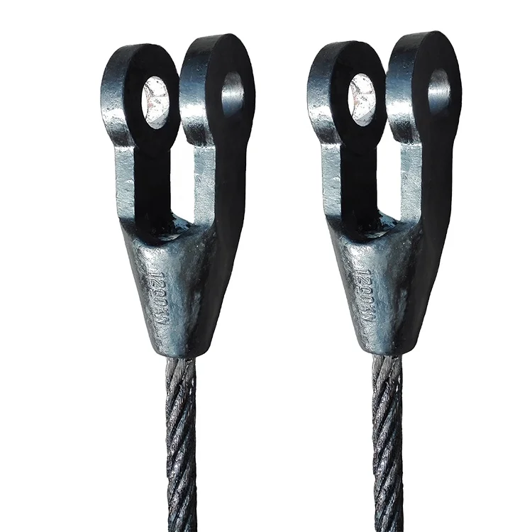
wedge socket for wire rope free sample
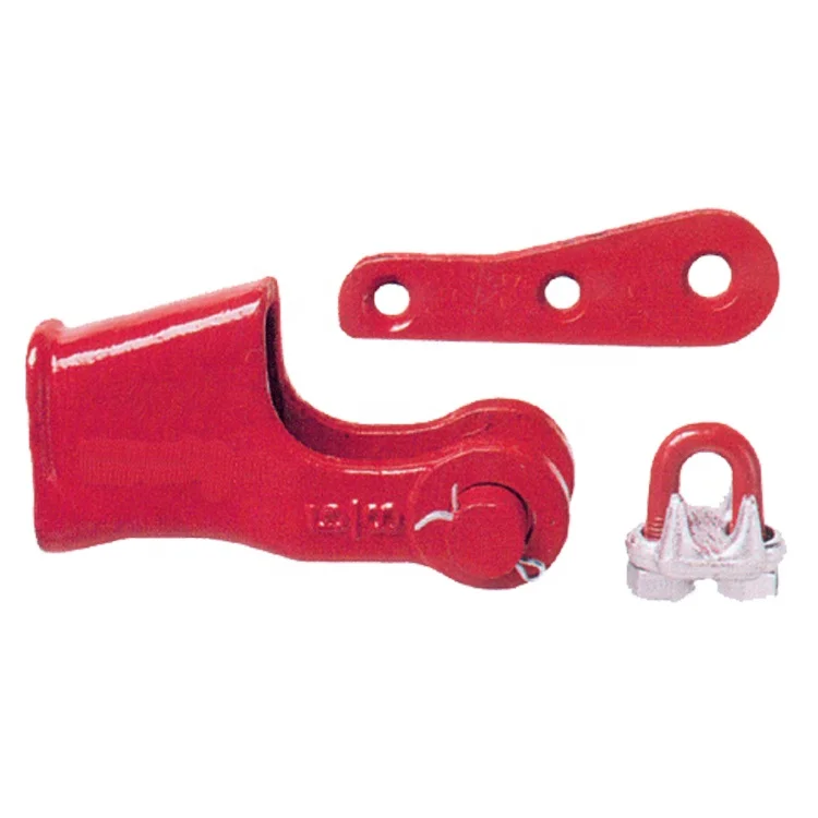
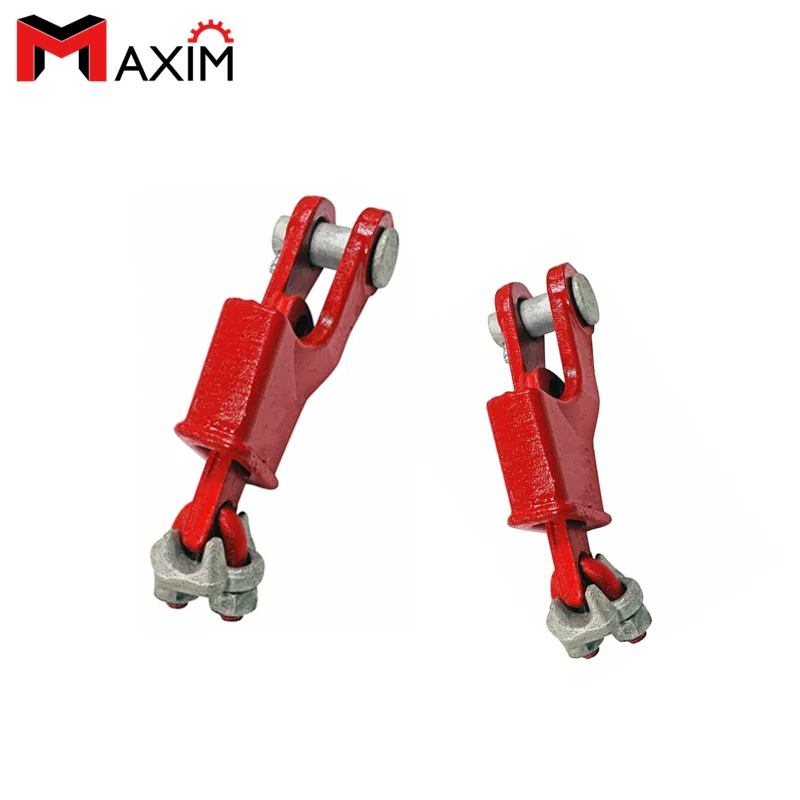
When the steel wire rope has been seated in the wedge socket by the load on the rope, the wedge shall be visible, and at least two wire rope retaining clips shall be provided to attach the termination side to the load-carrying side of the rope (see Figure 2.20.9.5). The first clip shall be placed a maximum of 4 times the rope diameter above the socket, and the second clip shall be located within 8 times the rope diameter above the first clip. The purpose of the two clips is to retain the wedge and prevent the rope from slipping in the socket should the load on the rope be removed for any reason. The clips shall be designed and installed so that they do not distort or damage the rope in any manner.
- Meets or exceeds all requirements of ASME B30.26, including marking, ductility, safety factor, test load and temperature. In addition, these wedge locks meet other
critical performance requirements not included in the ASME B30.26 standard, such as fatigue strength, notched impact strength and material batch traceability.

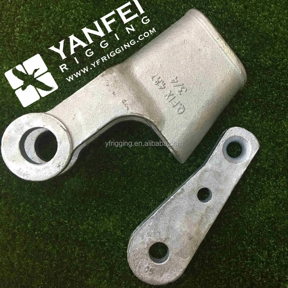
End terminations with wedge sockets are most popular with tower and mobile cranes although they do not generate as high as an strength efficiency rating as swaged sleeves, swaged sockets, or spelter sockets.
Depending on rope construction and type, their efficiency rating ranges between 75% and 80%. For detailed information ask the manufacturer of your wedge socket.
The installation of Python® rope into wedge sockets is similar to that of 6- or 8-strand wire rope. Here’s a quick run down of some of the do’s and dont’s:
Ensure that the rope end is welded and/or properly seized before inserting the rope into the socket. Failing to do so may cause the core to slip and/or the strands to loosen inflicting serious rope damage.
Wedge sockets are among the simplest devices for anchoring a wire rope or cable for any of numerous purposes. They are intended for "on the job" attachment and for quick rope replacement. Principal advantages are simplicity, ease and speed of applying and detaching. They are also used where conditions are such that spliced eyes cannot be reeved and would have to be made after the rope is in place. Wire lines, commonly called cable, are used with lifting machines such as cranes. The wire hangs over a pulley from the crane and has a free end dangling down below. Wedge sockets are typically connected to this lower end of the wire rope and a hook or other member is attached to the socket. Thus, the socket provides means for coupling the free end of the wire rope to buckets or other apparatus which are then lifted or transported by a crane.
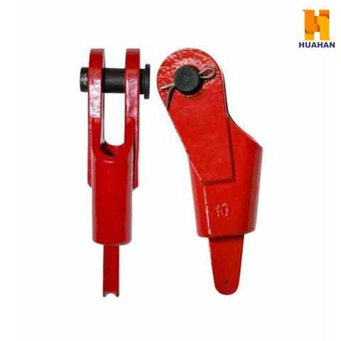
Typical open wedge sockets include a wedge member and a socket for receiving the wedge member. A cable is captured in the socket by passing the free end of the cable through the socket, laying the wedge on the cable, and returning the free end of the cable over the wedge and back through the socket. As the size of the wire rope increases, the difficulty of this manual manipulation increases. To achieve the turnback, much more wire rope is used than is necessary for the final assembly. After assembly, the excess is trimmed off and discarded.
Some device is usually attached to the dead end segment of the wire rope to facilitate the moving of the wedge into the socket when the initial load is applied. Also this device prevents slippage if slack is induced into the system by something striking the stub end of the wire rope or the small end of the wedge. Another problem is that the wire rope can be installed in reverse position which will cause a relatively sharp kink in the wire rope when the wire rope is applied.
There has been similar effort to overcome some of the concerns listed above by using a wedge as socket inside a concave shaped basket. Typical of this type socket is that represented by U.S. Pat. No. 3,351,986. This type socket overcomes some of the concerns with the more commonly used wedge socket. However, those designs have some shortcomings, such as: 1. They require a high degree of initial clamping effort to insure that the wire rope will not slip through the rope channel during initial load application. Most of the present clamps of this general configuration contains a U-bolt. This clamping effort comes from such U-bolt which after initial load application must be retightened. This concentrated clamping force on the live end of the wire rope has a reducing effect on the potential fatigue life of the termination. Also, it has a reducing effect on the termination efficiency. The U-bolt clamps wedge elements outside of the basket and is unsightly and can snag objects with which it might come in contact. Further the wedge surface that contacts interior surface of the socket is convex allowing for concentrated load transmission to the socket.
As additional background, it should be stated that the efficiency of a termination (end of wire rope secured in socket) is a rating derived as a ratio of the rated catalog working strength of the wire rope to the breaking strength of the wire rope when used in a termination. As an explanation of the significance of this rating the following example is offered in which a certain size and class of wire rope has a rated catalog ultimate strength of fifty thousand pounds. If this wire rope were used with the wedge socket having an efficiency of termination of eighty percent then the expected resulting ultimate strength of the wire rope would be forty thousand pounds. The reduction in the relative strength of the wire rope is caused by the severe compression of the wire rope in the region where the wire rope/wedge/basket interface.
A system designer must use the termination rating to derive the proper rated capacity of the wire rope. For example, under OSHA regulations, the running lines on a mobile crane must have a safety factor of at least 3.5. Using a crane that has an adequate line pull and stability and using a fifty thousand pound wire rope with an eighty percent wedge socket for a single part line, the maximum allowable load to be lifted would be 50,000×0.8 divided by 3.5=11,428 pounds. If however,the wedge socket has a ninty five percent efficiency rating, the maximum allowable load would be 50,000×0.95 divided by 3.5=13,571 pounds. The importance of a high termination rating is thus quite apparent.
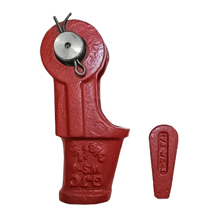
This is an improved wedge socket for wire rope. The system includes a wire rope and a wedge which has a hollow housing or basket which has two opposite planar surfaces which converge or taper toward the smaller end of the opening. A wedge is made up of two elements and has a wire rope passage therethrough. Each wedge element has a planar tapering surface which mates with one of the interior planar surface of the basket. The passage has a restriction or throat near the larger end of the wedge so that when the two elements of the wedges are forced onto the wire rope together there is a reoriented zone of wire rope. Means such as bolts, is provided to pull the wedges together at this restricted area so that the wire cable is reoriented and at least partially flattened in the restricted section. When finally assembled, the bolts are completely within the basket or housing so that they cannot snag on anything. As load is applied to the wire rope, the wedge elements are pulled tighter and tighter into the basket and as they are pulled tighter and tighter the wire rope passage grips the wire rope more and more firmly. The inside of the wire rope passage through the wedge outside the restricted area is provided with a configuration to match the lay of wire rope.
FIG. 11 is an elevational view of the side of wedge element showing the wire rope passage and that portion which mates with the like portion of the other wedge element.
Attention is first directed to FIG. 1 which shows an elevational view of the socket of my invention. Shown thereon is the housing or basket 10 with wire rope 12 held therein by wedge 14. An attaching pin 20 with cotter pin 22 is provided. Attention is next directed to FIG. 2 which shows the wire rope 12 held in passage 18 of first wedge element 16. There will be two such wedge elements 16 and each will have a wire line or rope passage 18 therethrough. One wedge 16 sits on top of a second wedge to form nearly circular rope passage fluted therethrough.
The general shape of the wedge element can quickly be seen in FIGS. 10, 11 and 12. As shown in FIG. 12 one surface of the wedge element 16 is provided with a sloping or tapered surface 40. As can be seen in FIG. 3 this wedge surface 40 mates with the interior sloping surface 41 of basket 10. As also shown in FIG. 3 basket 10 has a second sloping surface 43 which is opposite sloping surface 41. There are two wedge elements inside the basket. They are wedge element 16 and wedge element 17. These elements are identical and will be described more fully in relation to FIGS. 10 through 16. An elevational view of the basket is shown in FIG. 6 and shows in dotted lines indicating sloping faces 41 and 43. FIGS. 7, 8 and 9 are taken on the lines 7--7, 8--8 and 9--9 of FIG. 6 and show the shape of the basket. The basket has a self-holding wedge angle B as shown in FIG. 3 between the two planar surfaces 41 and 43. Preferably this angle B is typically about 12° but the invention is not limited to that particular angle.
FIG. 11 shows the wedge element 16 on the non-wedge or flat side having passage 18 for receiving the wire line. There is a section 24 which is wider in this plane but is restricted in perpendicular plane. This section has bolt holes 26, 28, 30 and 32 extending therethrough. Trough 18 is provided with a Roddle configuration 34 having individual spirals 19 as shown in FIG. 4 and which match the right hand lay wire rope. The configuration will of course be designed to match the particular wire rope being used. FIG. 10 shows the "other" side of the wedge element from that shown in FIG. 11 and shows lands 36, 38 and 68 thereon. Attention is next directed to FIG. 12 which shows a side view of the wedge element of FIG. 11 and shows a wedge shaped planar side 40. As shown more clearly in FIGS. 13 and 14 the side 40 includes lands 36 and 38.
As clearly shown in FIGS. 3 and 5 the passage 18 is provided with a throat section 24 which can be called a wire rope reoriented zone 50 when the wire rope is secured therein. As can be seen in FIG. 5 throat section 24 has a planar surface 52. Wedge element 17 has a similar planar surface 54. As shown in FIGS. 2 and 5 there are four clamping bolts 56, 58, 60 and 62 which holds the wedge element 16 and wedege element 17 together. These bolts go through holes 26, 28, 30 and 32 as shown in FIGS. 10 and 11. These bolts are held by suitable multiple nuts 64. Alternatively, a single bar with two tapped holes in it may be used in lieu of multiple nuts. The clamping bolts 56, 58, 69 and 62 are not fully threaded. This is so that there will be provided a non-threaded or smooth surface 66 on each bolt which will contact the wire line 12. Wedge element 16 in the area adjacent the restricted area 50 has a single exterior land 68. The passage 18 has flutes 19 throughout the configuration 34.
Attention will now be directed to the assembly of this device so that wire rope 12 will be firmly anchored therein. To accomplish this the cable 12 is first inserted through the passage 70 of the basket with the wedge element 16 and 17 removed. The wire is inserted far enough through so that the wedge elements 16 and 17 can be placed about the end of the wire rope. While in this extended position, screws 56, 58, 60 and 62 are inserted and tightened to pull the two wedge elements 16 and 17 toward each other. Sufficient tightening is done to obtain a reoriented zone of wire rope as shown in FIG. 5. The wire rope in the region of the clamping screws then is forced into reorientation that increases the friction factor of the wire rope relative to the socket. By using this multiple bolts for clamping the wedge elements to the wire rope significantly reduces the effort required per bolt. FIG. 4 shows how the strands of the wire rope 12 nestle into flutes 19 which are shown in FIG. 11 are made to match the lay of the wire rope. The assembled wedge elements 16 and 17 and wire rope 12 can then enter into the passage of basket 10 between planar surfaces 41 and 43. The wedge socket has now been firmly attached to the wire rope and is ready for use. This can be accomplished merely by inserting the attaching pin 20 as shown in FIGS. 1 and 2 to support a hook or whatever else might be desired. Force on the wire line and resistance of weight supported by the pin 20 will force the wedge elements tighter together.
When using this improved wedge socket only a straight section of wire rope is used in the assembly of it and it does not require that the wire rope be turned back at a relatively sharp bending radius. In my invention the concentrated securing force of the wedge segments to the wire rope is done at a location away from the critical stress region of the wire rope where the wire rope first interfaces with the wedge segments.
When the wedge socket is assembled to the wire rope, the clamping bolts 56, 58, 60 and 62 are in a protected position inside the basket. This gives improved appearance and also prevents the bolts from snagging on to objects.
The wire rope 12 in the region of the clamping screws, is forced into reorientation which increases the friction factor of the wire rope relative to the socket.
The friction factor resulting from the reorientation of the wire rope 12 is of such a magnitude that the clamping force required is 250% less than that used in conventional sockets.
The reorientation of the wire rope 12 in the clamping region causes the wire rope to bear against the clamping bolts offering additional resistance to the bolts backing out.
Tests show that the efficiency of the improved wedge socket of my invention is ninety five percent. This is higher than any known percentage of known conventional sockets.
The wire rope fatigue life is enhanced because the clamping force has not been concentrated in the critical stress section where the wire rope first interfaces with the wedge segments.
Using three lands, 38, 36 and 68 on the surface of the wedge segment that contacts the basket 10 provided for better distribution of the forces between the wire rope and the wedge segement and between the wedge segment and the basket.
The small end of the wedges and the end of the socket ear sections are blunted in shape so that by impacting one of the blunted surfaces while resting the other blunted surface upon an immovable object, the wedge segment can be removed from the basket.
While the invention has been described with a certain degree of particularity, it is manifest that many changes may be made in the details of construction and the arrangement of components without departing from the spirit and scope of this disclosure. It is understood that the invention is not limited to the embodiments set forth herein for purposes of exemplification, but is to be limited only by the scope of the attached claim or claims, including the full range of equivalency to which each element thereof is entitled.
Jiangsu Gostern Rigging Co., Ltd. was established in the year of 2001 in China. The company covers an area of 33000 square meters, more than 600 employees. It is a specialized slings company that can design, manufacture and market. The company has a strong technical ability, scientific technology procedures, testing equipment, and a perfect quality system. The company has achieved the ISO9001-2000 quality system certification. The quality of the products has been insured by the Chinese people and property insurance companies.
Our main products are wire rope slings, webbing slings, braided ropes, ratchet straps, tow straps, chain slings, steel plate lifting clamps, hanging beams, rigging accessories. The products are widely used in machinery, metallurgy, petroleum, chemical industrial, ports, shipbuilding and other fields.

2003-01.Slovenski inštitut za standardizacijo. Razmnoževanje celote ali delov tega standarda ni dovoljeno.Endverbindungen für Drahtseile aus Stahldraht - Sicherheit - Teil 7: Symmetrische SeilschlösserTerminaisons pour câbles en acier - Sécurité - Partie 7 : Boîte a coin symétriqueTerminations for steel wire ropes - Safety - Part 7: Symmetric wedge socket77.140.99Drugi železni in jekleni izdelkiOther iron and steel products53.020.30Pribor za dvigalno opremoAccessories for lifting equipmentICS:Ta slovenski standard je istoveten z:EN 13411-7:2006SIST EN 13411-7:2006en01-oktober-2006SIST EN 13411-7:2006SLOVENSKI
EUROPEAN STANDARDNORME EUROPÉENNEEUROPÄISCHE NORMEN 13411-7June 2006ICS 21.060.70; 53.020.30 English VersionTerminations for steel wire ropes - Safety - Part 7: Symmetricwedge socketTerminaisons pour câbles en acier - Sécurité - Partie 7 :Boîte à coin symétriqueEndverbindungen für Drahtseile aus Stahldraht - Sicherheit- Teil 7: Symmetrische SeilschlösserThis European Standard was approved by CEN on 10 May 2006.CEN members are bound to comply with the CEN/CENELEC Internal Regulations which stipulate the conditions for giving this EuropeanStandard the status of a national standard without any alteration. Up-to-date lists and bibliographical references concerning such nationalstandards may be obtained on application to the Central Secretariat or to any CEN member.This European Standard exists in three official versions (English, French, German). A version in any other language made by translationunder the responsibility of a CEN member into its own language and notified to the Central Secretariat has the same status as the officialversions.CEN members are the national standards bodies of Austria, Belgium, Cyprus, Czech Republic, Denmark, Estonia, Finland, France,Germany, Greece, Hungary, Iceland, Ireland, Italy, Latvia, Lithuania, Luxembourg, Malta, Netherlands, Norway, Poland, Portugal, Romania,Slovakia, Slovenia, Spain, Sweden, Switzerland and United Kingdom.EUROPEAN COMMITTEE FOR STANDARDIZATIONCOMITÉ EUROPÉEN DE NORMALISATIONEUROPÄISCHES KOMITEE FÜR NORMUNGManagement Centre: rue de Stassart, 36
B-1050 Brussels© 2006 CENAll rights of exploitation in any form and by any means reservedworldwide for CEN national Members.Ref. No. EN 13411-7:2006: ESIST EN 13411-7:2006
EN 13411-7:2006 (E) 2 Contents Page Foreword..............................................................................................................................................................3 Introduction.........................................................................................................................................................4 1 Scope......................................................................................................................................................5 2 Normative references............................................................................................................................5 3 Terms and definitions...........................................................................................................................6 4 List of significant hazards....................................................................................................................6 5 Safety requirements and/or measures................................................................................................7 6 Verification of safety requirements......................................................................................................8 7 Information for use..............................................................................................................................11 Annex A (informative)
Construction and sizes for one design of symmetric wedge socket with welded socket body.............................................................................................................................13 Annex B (informative)
Recommendations for safe use and inspection of symmetric wedge sockets conforming to Annex A, to be provided by the manufacturer..........................................16 Annex ZA (informative)
Relationship between this European Standard and the Essential Requirements of EU Directive 95/16/EC............................................................................................18 Annex ZB (informative)
Relationship between this European Standard and the Essential Requirements of EU Directive 98/37/EC............................................................................................19 Bibliography......................................................................................................................................................20
EN 13411-7:2006 (E) 3 Foreword This document (EN 13411-7:2006) has been prepared by Technical Committee CEN/TC 168 “Chains, ropes, webbing, slings and accessories - Safety”, the secretariat of which is held by BSI. This European Standard shall be given the status of a national standard, either by publication of an identical text or by endorsement, at the latest by December 2006, and conflicting national standards shall be withdrawn at the latest by December 2006. This document has been prepared under a mandate given to CEN by the European Commission and the European Free Trade Association, and supports essential requirements of EU Directive(s). For relationship with EU Directive(s), see informative Annexes ZA and ZB, which are integral parts of this document. EN 13411 consists of the following parts: Part 1: Thimbles for steel wire rope slings Part 2: Splicing of eyes for steel wire rope slings Part 3: Ferrules and ferrule-securing Part 4: Metal and resin socketing Part 5: U-bolt wire rope grips Part 6: Asymmetric wedge socket Part 7: Symmetric wedge socket This is the first edition of this Part of this European Standard. According to the CEN/CENELEC Internal Regulations, the national standards organizations of the following countries are bound to implement this European Standard: Austria, Belgium, Cyprus, Czech Republic, Denmark, Estonia, Finland, France, Germany, Greece, Hungary, Iceland, Ireland, Italy, Latvia, Lithuania, Luxembourg, Malta, Netherlands, Norway, Poland, Portugal, Romania, Slovakia, Slovenia, Spain, Sweden, Switzerland and United Kingdom. SIST EN 13411-7:2006
EN 13411-7:2006 (E) 4 Introduction This European Standard is a type C standard as stated in EN 12100. This European Standard has been prepared to provide a means of conforming with the essential safety requirements of the Machinery Directive and the Lift Directive and associated EFTA regulations. The wedge socket concerned and the extent to which hazards, hazardous situations and events are covered are indicated in the scope of this standard part of the standard. When provisions of this type C standard are different from those which are stated in type A or B standards, the provisions of this type C standard take precedence over the provisions of the other standards for symmetric wedge sockets that have been designed and produced according to the provisions of this type C standard. Purchasers ordering to this standards are advised to specify in their purchasing contract that the supplier operates a quality assurance system applicable to the relevant part of this standard (e.g. EN ISO 9001) to ensure themselves that products claiming to comply consistently achieve the required level of quality.
EN 13411-7:2006 (E) 5 1 Scope This European Standard specifies the minimum requirements for symmetrical wedge socket terminations for stranded steel wire ropes conforming to EN 12385-5 for lifts. This European Standard covers those symmetric wedge sockets intended for use at temperatures between
-20 °C and 100 °C. This European Standard only covers those symmetric wedge sockets that have welded socket bodies. An example of the construction and sizes of a symmetric wedge socket is given in informative Annex A. The informative Annex B gives the recommendations for the safe use and inspection of symmetric wedge socket according to Annex A. This European Standard deals with all significant hazards, hazardous situations and events relevant to symmetric wedge sockets for terminations for steel wire ropes, when used as intended and under conditions of misuse which are reasonable foreseeable by the manufacturer. The hazards covered by this European Standard are identified in Clause 4. This European Standard applies to symmetric wedge sockets, which are manufactured after the date of its publication. 2 Normative references The following referenced documents are indispensable for the application of this document. For dated references, only the edition cited applies. For undated references, the latest edition of the referenced document (including any amendments) applies. EN 1050:1996,
Metallic materials — Charpy impact test — Part 1: Test method EN 12385-2:2002, Steel wire ropes — Safety — Part 2: Definitions, designation and classification EN 12385-5:2002,
Steel wire ropes — Safety — Part 5: Stranded ropes for lifts EN ISO 4063, Welding and allied processes - Nomenclature of processes and reference numbers (ISO 4063:1998) EN ISO 5817,
Welding — Fusion-welded joints in steel, nickel, titanium and their alloys (beam welding excluded) — Quality levels for imperfections (ISO 5817:2003) EN ISO 7500-1:2004,
Metallic materials — Verification of static uniaxial testing machines — Part 1: Tension/compression testing machines — Verification and calibration of the force-measuring system
Basic terminology, methodology (ISO 12100-1:2003) EN ISO 12100-2:2003, Safety of machinery — Basic concepts, general principles for design — Part 2: Technical principles (ISO 12100-2:2003) SIST EN 13411-7:2006
EN ISO 12100-2:2003, EN 12385-2:2002 and the following apply. 3.1 symmetric wedge socket assembly consisting of a socket body, wedge, and pin and securing means for the pin; when assembled the centre line of the pin is marginally offset (by one half rope diameter, see Figure B.1) to the longitudinal axis of the live portion of the rope
3.2 socket body principal component of a wedge socket termination having an internal tapered form suitable for receiving a wedge (see 3.3) and the rope with which the wedge is associated, see Figure A.1 3.3 wedge flat tapered component with peripheral groove, suitable for fitting into a tapered socket body to accommodate a rope of matching nominal diameter, see Figure A.1 3.4 pin removable component intended to facilitate connection of the socket body to its anchorage point 3.5 lot number of symmetric wedge sockets from which samples are selected for testing purposes which are of the same type and dimension, each of their constituent components manufactured during the same production run from material of the same cast and subjected to the same heat treatment process 4 List of significant hazards This European Standard contains all the significant hazards, hazardous situations and events, as far as they are dealt with in this European Standard, identified by risk assessment as significant for this type of steel wire rope termination that require action to eliminate or reduce the risk. In particular, the hazard caused by accidental release of a load, or release of a load due to failure of a symmetric wedge socket, puts at risk, either directly or indirectly, the safety or health of those persons within the hazard zone. Errors in the fitting of accessories can also lead to premature failure and this European Standard contains dimensional and geometrical requirements to allow correct fit. Table 1 contains those hazards that require action to reduce risk identified by risk assessment as being specific and significant for symmetric wedge sockets. SIST EN 13411-7:2006
5 Safety requirements and/or measures 5.1 Geometry of wedge and socket body Symmetric wedge socket terminations for ropes shall conform to the following geometrical criteria
(see Figure A.1): • the wedge groove angle (.) shall be the same as the socket angle in the body (); • the wedge shall be symmetric; • the internal side surfaces of the socket body and the wedge in contact with the rope shall be straight; • the grooves of the body and the wedge shall have no surface irregularities, such as, protrusions or joints which could influence the intimate contact with the rope; • the clamping length between the socket body and the wedge shall be at least 7,3 times the nominal rope diameter d; • the radius r3 of the wedge at the bottom of the groove at the large end shall be at least 1 times the nominal diameter d of the rope. 5.2 Security of the pin The pin shall be provided with a means for securing it in position when in operation. 5.3 Welded socket body The welding and allied process shall conform to one of those specified in EN ISO 4063. The person who supervises the production process shall be trained in the chosen welding process. The quality of the welding joint shall be in accordance with assessment group B of EN ISO 5817:2003. There shall be no melted on weld chips. The ligament distance in the root of the welding joint shall be 1 mm for material thickness up to 6 mm and
1,5 mm for material thickness more than 6 mm up to and including 12 mm. The penetration of the root of the welding shall be avoided. There shall be no increase of the welding joint in the area of contact with the rope. The welding joint shall have a bonding area of at least 70 % at the joint edge. SIST EN 13411-7:2006
EN 13411-7:2006 (E) 8 Any offset of the edges of the body halves shall be limited to 0,5 mm for material thickness up to 6 mm and 0,8 mm for material thickness more than 6 mm up to and including 12 mm. 5.4 Mechanical properties 5.4.1 General The required mechanical properties take into account, that symmetric wedge sockets in combination with stranded ropes for lifts to EN 12385-5 have to be used with a minimum coefficient of use of 5 for lifting goods and 10 for lifting of persons. 5.4.2 Termination efficiency When tested in accordance with 6.2.2 the efficiency of the assembled termination shall be at least 80 % of the minimum breaking force of the rope without any movement between the rope and the termination and any deformation of the wedge and the socket. 5.4.3 Fatigue behaviour of the socket body and pin When tested in accordance with 6.2.3 the socket body, wedge and pin shall not exhibit any indications of cracks after 75 000 load cycles. The socket and wedge shall also exhibit no sign of local permanent deformation. 5.4.4 Low temperature properties The material of the socket body and pin, when tested in accordance to 6.2.4 shall possess a minimum low temperature ductility at –20 °C as follows: Minimum average Charpy impact value at 27 J, with no individual value less than 18 J. 6 Verification of safety requirements 6.1 Qualifications of personnel All testing and examination shall be carried out by a competent person. 6.2 Type testing 6.2.1 General Two type tests shall be carried out for each requirement, in accordance with 6.2.2 to 6.2.3 on assembled terminations of each design, material and method of manufacture, using the highest minimum breaking force of rope as defined in EN 12385-5 for which the socket is designed. If the dimensional criteria, the material or the method of manufacture are subsequently varied outside the usual manufacturing tolerances, the type tests shall be repeated. The testing machine shall conform to the requirements of EN ISO 7500-1. 6.2.2 Tensile efficiency test Subject the assembled termination to an initial load of 60 % of the minimum breaking force of the rope, then increase the loading at a rate of not more than 0,5 % of the breaking force per second in the tensile testing machine. The test shall be continued until either rope breaks or slips out of the socket. SIST EN 13411-7:2006
EN 13411-7:2006 (E) 9 If terminations are tested in pairs, the distance between the inner faces of the socket bodies shall be at least 30d. 6.2.3 Fatigue test The test shall be carried out on an in-line tensile fatigue machine. The termination shall not be allowed to rotate and the test shall consist of the application of the cycle force from 15 % to 30 % of the minimum breaking force of the rope along the rope axis for 75 000 cycles. The frequency of the force shall not exceed 5 Hz. The component parts shall be subject to dye penetrant in accordance with EN 1289 or magnetic particle inspection in accordance with EN 1290, both before and after the fatigue test to enable any crack propagation as a result of fatigue to be readily identified. NOTE More than one rope may be required to enable the socket body to achieve 75 000 cycles. 6.2.4 Acceptance criteria for type testing If the assemblies pass all of the above tests, the symmetric wedge socket
Westech Rigging Supply rigging and safety gear is only intended to be used by competent trained professionals. Misuse of the rigging and safety gear can result in serious injury up to and including loss of life. As such, Westech Rigging Supply disclaims liability for any misuse or incorrect product selection by our customers.
Rigging and safety gear purchased from Westech Rigging Supply should be used in strict accordance with all industry and OSHA standards. At no time should rigging or safety gear be used beyond its certified load ratings (aka Working Load Limits). Normal wear and tear should be expected with use of rigging and safety gear; therefore, all gear should be thoroughly inspected before each and every use. Worn or unsafe rigging and safety gear should never be used.

Everyone who works with large draglines knows the problem of wedge removal. One assembly we tested required 160,000 pounds of pressure to break the wedge free.
Our patented Easy Out Socket system eliminates the need for explosives, hydraulic presses or tractor pulls. The only tool required is the torch used to cut the wire cable.
To remove a wedge, cut the rope at the bend and near the small end of the wedge. Then, just burn through the three spacer blocks between the wedge halves, allowing the wedge to collapse so you can easily remove it. Using a spare Columbia wedge, you can immediately install a rope and be up and running. Replacing the wedge spacer assembly is a quick weld job, using a Columbia Steel spacer kit. The Easy Out socket/wedge system is available for draglines using 3 to 5-inch rope.
Users of our Easy Out Socket system report that it is the first advanced design which really works. Forces are distributed to eliminate distortion of the wedge, so your rigging remains safe and secure.


 8613371530291