
welding wire rope together manufacturer

Welding two ropes together is common in the steel industry. If properly done, welding may develop sufficient strength to complete the rope installation. However, the welded portion of the rope is rather stiff, and the welded steel wire material may become brittle. Since the welded portion has to pass over sheaves, there is the danger that the weld may break.
If installing Python® wire rope as well as all non-rotating types we do not recommend the welding procedure. Welding might damage the seizings and the rope may unravel getting damaged beyond repair.
A common method for heavy crane rope installations. A steel sleeve only slightly larger than the rope diameter is swaged on to the rope end and a small auxiliary cable protrudes from the sleeve. Either, the old rope is furnished also with a becket loop, or the old rope will be connected to the becket loop with a cable grip.
Non-rotating rope must be installed with a swivel between old and new ropes. The old rope may have developed torque during it’s working life and we must ensure that this torque is not transferred to the new rope.
Python® types Multi and Super 8 may be installed with a swivel. In fact, if you have to change either of these constructions for a 6-strand rope, particularly when this rope has a different lay direction, a swivel is of definite benefit.
Python® Power 9 and Python® Ultra must not be installed with a swivel. Doing so will unlay the rope and damage it beyond repair. Use two cable grips and connect them with an auxiliary cable.
When using cable grips, the end of the grips have to be tightly seized on to the rope body to prevent accidental slip-out of the rope. Alternately, you may wrap the grip end with a strong reinforced industrial strength adhesive tape.
PA welding machines command attention with their efficient design and construction. The manual clamping device with optimized ergonomics is the basis for this robust but also inexpensive version.
In SE as well as PA welding machines, the wire rope or cable ends are inserted into a tube made of ceramic or graphite until the ends touch. Ceramic is the material of first choice here. As a rule, we use graphite tubes from > 400 mm² (version G).
After starting the welding process, the two ends are welded together by the current which then flows and the upset force which is applied. Optionally, preheating is carried out to achieve an optimal temperature profile. After completion of the weld, the tube is broken off. The surface at the weld is burr-free, clean, smooth and only imperceptibly thicker.
Operation of STRECKER welding machines is easy to learn. The pneumatic welding clamping fixture is standard equipment starting with the SE12 and meets the highest demands in terms of convenience and ergonomics (the same applies for the PA100-SE). The upset pressure is then also pneumatic. The compact and robust machine design with intuitive operator guidance is designed for industrial use in production.
MS and MK welding machines are designed for larger cross-sections, the highest quality and documented reproducibility with wire ropes and cables of up to 2500 mm² made of aluminium or copper. We meet the highest requirements for the smallest possible single-wire setups, class 2 to class 6 applications, as well as for high-strength alloys. Even wire ropes with different diameters can be welded with a minimized heat-affected zone. The burr is removed in the welding clamping fixture and caught in the machine. The result is a homogeneous, very thin and pore- and burr-free connection. The MS and MK series are equipped with our innovative FullParameterControl (FPC) control system as standard. The complete welding recipe is stored safely and with accurate repeatability in the controller. All settings of the machine are made automatically according to the recipe selected with no operator intervention. As an option, the quality of the welding process can be monitored with the STRECKER parameter monitoring system.
A 3-phase direct current transformer is employed to counteract the high current consumption or short-term peak load that occurs when welding very large conductor cable cross-sections. This reduces the current consumption.
After starting the welding process, the two ends are welded together by the current which then flows and the upset force which is applied. Optionally, preheating is carried out to achieve an optimal temperature profile.
Operation of STRECKER welding machines is easy to learn. They meet the highest standards of convenience and ergonomics. The compact and robust machine design with intuitive operator guidance is designed for industrial use in production.
Parting guns and battery parting guns are optimized for daily use in production. They enable precise separation processes in which each individual wire in the separation plane is connected while retaining the same diameter. The basis for trouble-free further processing.
Our company history starts from wire manufacturing. Our staff has long experience in the wire industry and in particular has extensive wire manufacturing experience that is directly transferred into our equipment.
Our tutoring services can offer wire drawing classes, stranding classes and process management classes. In addition to this we can supply in particular, technical know how, for PC strand and Tyre cord manufacturing.

After more than thirty years of leadership in manufacturing and nearly a decade with the company, Kathleen Edge, Southwire’s Executive Vice President of Operations, will retire from Southwire at the end of 2022.
Single conductor portable cord consists of welding cable, DLO cable, Type W, Stage Lighting cable and Super Vu-Tron Welding cable. We cut it to the requested length and crimp Burndy Lugs to one end or both ends depending on the request. We can also add heat shrink tubing to cover the transition between insulation and lug if needed. Copper wire is manufactured to connect from point A to point B so WesBell likes to get actively involved with each customer to see if we can help prepare their wire and cable products before shipping it.
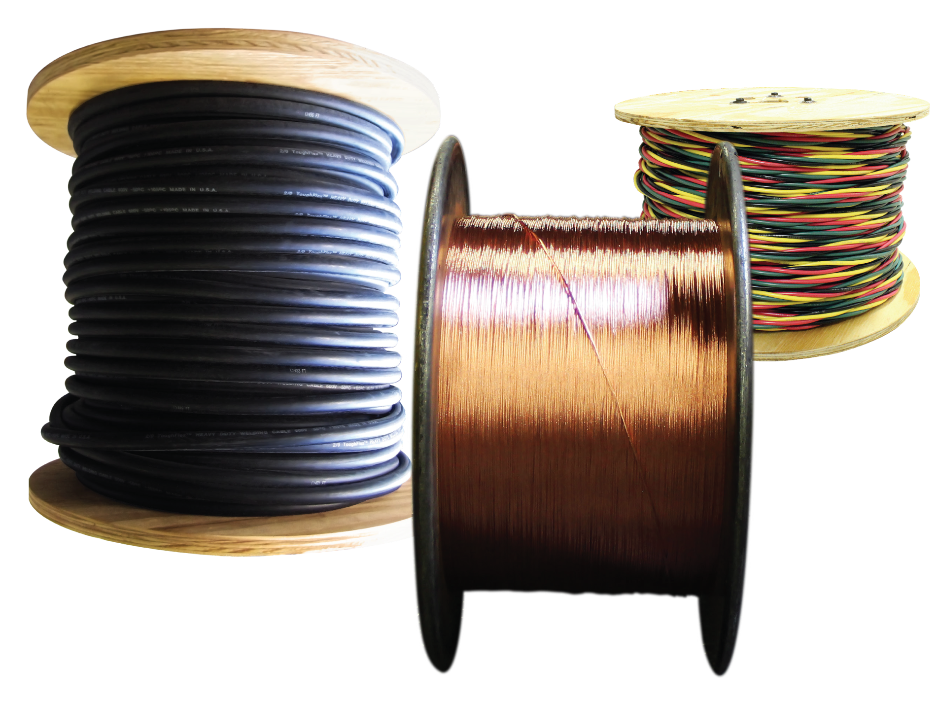
We buy our cable products direct from the manufacturer on 2500 and 5000 foot spools in order to receive bulk pricing discounts. Many customers have the tooling to prepare the cables in house so they order spools in bulk. We spool wire and cable products for free, so you can request any length while placing your order online. For instance, instead of ordering 500 feet you can order 10 coils of 50 feet at no charge.
For customer that want to prepare their own welding cable assemblies please remember that you can also buy the Burndy lugs and heat shrink tubing from us as well. As with every industry the price is determined by the quantity, but we sell one lug at a time to anyone that requests it. If you place an order online for the first time you can take advantage of our 5% discount if you set up a customer account with us. You can also call to let us know you’re placing a larger order over $1000 and we may be able to give you a discount on top of our online pricing.
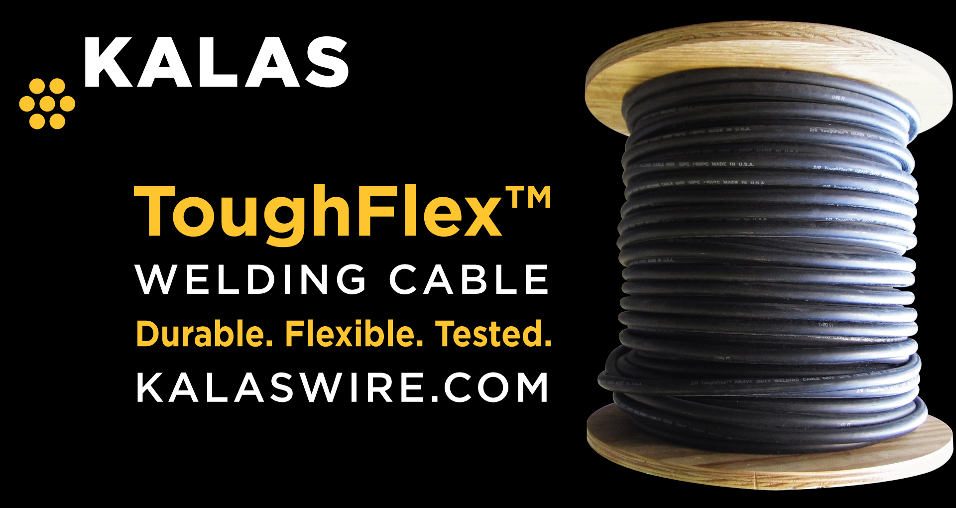
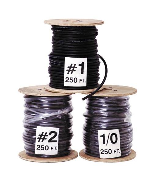
The most standard types of single conductor portable cord that are used to manufacture cable assemblies are welding cable, Super Vu-Tron welding cable, DLO cable, Type W cable and stage lighting cable. Welding cable is the most basic and it’s rated for 600 volts and 105°C. It does the job well but doesn’t come with any UL or CSA approvals or added weather protection. Super Vu-Tron cables come in orange and have added protection and more approvals (UL, CSA, MSHA, etc.). The gauge sizes range from 6 AWG up to 4/0 (or 0000 AWG). DLO cable is rated for 2000 volts so the insulation is much thicker, and it’s also the only one of the group that has tinned copper strands. Type W is also rated for 2000 volts and differs from DLO through its higher level of flexibility and bare copper strands. Finally, stage lighting cable is fairly specific to the entertainment industry for setting up the lighting on stages indoors and outdoors.
Finally, the last step of the process will be to decide if you want us to create and complete the assemblies for you or if you want to do it yourself. This is a simple process of selecting Yes or No under Step 5, “Cut and assemble your order of wire and lugs”. You will see the Services Total change at the bottom, which is different from the product total. Your product total is the cable and lugs while the Services total is the labor it takes for us to build them and quality check them for you. Please make any necessary or applicable notes in the provided notes section but rest assured, we’ll be calling you before we start to complete the order!

Stainless steel wires are increasingly present in medical applications which rely on their attractive combination of corrosion resistance, durability and mechanical properties.
Our multi-site ISO 9001:2015 registration by BSI covers the manufacture and distribution of round, stranded and shaped stainless, nickel, copper, zinc, and other alloy bar and wire products in various sizes and tempers, including ferrous and nonferrous welding wire.
Our multi-site ISO 9001:2015 registration by BSI covers the manufacture and distribution of round, stranded and shaped stainless, nickel, copper, zinc, and other alloy bar and wire products in various sizes and tempers, including ferrous and nonferrous welding wire.
AS9100:2016 and ISO 9001:2015 certification by Smithers Quality Assessments for the CWI-PERRIS, CA facility; focusing on Aerospace Market needs. CWI-PERRIS facility manufactures and distributes round, stranded, and shaped stainless steel, nickel, copper, zinc, and other alloy wire, bar, and cut-to-length products.
Our multi-site ISO 9001:2015 registration by BSI covers the manufacture and distribution of round, stranded and shaped stainless, nickel, copper, zinc, and other alloy bar and wire products in various sizes and tempers, including ferrous and nonferrous welding wire.
Our multi-site ISO 9001:2015 registration by BSI covers the manufacture and distribution of round, stranded and shaped stainless, nickel, copper, zinc, and other alloy bar and wire products in various sizes and tempers, including ferrous and nonferrous welding wire.
Our multi-site ISO 9001:2015 registration by BSI covers the manufacture and distribution of round, stranded and shaped stainless, nickel, copper, zinc, and other alloy bar and wire products in various sizes and tempers, including ferrous and nonferrous welding wire.
Sanlo Inc., located in Michigan City, Indiana, utilizes a Quality Management System registered by Preferred Registrar Group (PRG) that governs the processing and distribution of aircraft cable, strand, related hardware, wire rope, wire products, and other cores, including the extrusion of plastic jacketing and the manufacturing of assembled products.
CWI Strand Core is a manufacturing facility in Milton Florida, USA having a scope of manufacturing and supply of wire, rope, and assemblies. Strand Core maintains Qualified Products List (QPL) approval for many military applications (MIL-Spec Products), and specific customer approvals for manufacturing wire rope, cable, and strand for O.E.M and international specifications.
Loos & Co., Inc. is a world class manufacturer of specialty wire and cable products. We practice continual improvement to ensure customer satisfaction. Our business plan documents our commitment to meet customer requirements through specific, measureable objectives. Management reviews the effectiveness of our quality policy and quality management system on a regular basis. We communicate the results of these reviews to employees throughout the organization.
Loos & Co., Inc. is a world-class manufacturer of specialty wire and cable products. We practice continual improvement to ensure customer satisfaction. Our business plan documents our commitment to meet customer requirements through specific, measurable objectives. Management reviews the effectiveness of our quality policy and quality management system on a regular basis. We communicate the results of these reviews to employees throughout the organization.
The CWI UK facility, located in Rotherham UK, holds the Quality Management System ISO 9001:2015 Certificate maintains a quality management system certified by BSI for the manufacturing of stainless steel wire and nickel-based alloy wire to national and international standards and customer specifications and requirements.

Custom manufacturer of cables used in welding applications. Types of cables also include high temperature cables, PTFE cables, miniature cables, flexible cables, coaxial cables, flat cables, control cables, sensor cables, motor cables, pump winding cables and energy industry cables. Insulation materials include high performance thermoplastics, FEP, PFA, ETFE, PVC, polyethylene, polypropylene, polyurethane, TPR, PE and PP. Cables can be fabricated in different styles and power ratings. Capabilities include drawing copper, bunching, stranding, insulating, shielding, cabling, jacketing, custom printing and custom colors. Meets UL® standards.

GEN 317L Welding Wire is used for TIG, MIG and SAW welding. This stainless steel is often used for welding base metals with similar chemical composition. It has a lower carbon composition which reduces the possibility of intergranular carbide precipitation; which in turn increases the resistance to intergranular corrosion. It even offers resistance to pitting and crevice corrosion. This alloy is often used in large overlay applications.
All welding products are supplied with a certificate of conformance stating physical and mechanical properties including alloy chemistry. Every welding product is manufactured to have its own unique lot identification number for full lot traceability.
Multiple packaging and shipping options are available from our facilities in the US, Canada, and the UK. Learn more about our products, the industries and applications we support, and how CWI Generation4™ welding wire can work for you.
While you’re looking at welding wire, here are Three Reasons To Source Your Welding Wire and Demister Pads Together. By ordering all your turnaround supplies from CWI, you can reduce downtime, perform maintenance all at once, and work confidently knowing you are receiving only the highest quality products from a trusted manufacturer.

Rope diameter is specified by the user and is generally given in the equipment manufacturer’s instruction manual accompanying the machine on which the rope is to be used.
Rope diameters are determined by measuring the circle that just touches the extreme outer limits of the strands— that is, the greatest dimension that can be measured with a pair of parallel-jawed calipers or machinist’s caliper square. A mistake could be made by measuring the smaller dimension.
The right way to unreel.To unreel wire rope from a heavy reel, place a shaft through the center and jack up the reel far enough to clear the floor and revolve easily. One person holds the end of the rope and walks a straight line away from the reel, taking the wire rope off the top of the reel. A second person regulates the speed of the turning reel by holding a wood block against the flange as a brake, taking care to keep slack from developing on the reel, as this can easily cause a kink in the rope. Lightweight reels can be properly unreeled using a vertical shaft; the same care should be taken to keep the rope taut.
The wrong way to unreel.If a reel of wire rope is laid on its flange with its axis vertical to the floor and the rope unreeled by throwing off the turns, spirals will occur and kinks are likely to form in the rope. Wire rope always should be handled in a way that neither twists nor unlays it. If handled in a careless manner, reverse bends and kinks can easily occur.
The right way to uncoil.There is only one correct way to uncoil wire rope. One person must hold the end of the rope while a second person rolls the coil along the floor, backing away. The rope is allowed to uncoil naturally with the lay, without spiraling or twisting. Always uncoil wire rope as shown.
The wrong way to uncoil.If a coil of wire rope is laid flat on the floor and uncoiled by pulling it straight off, spirals will occur and kinking is likely. Torsions are put into the rope by every loop that is pulled off, and the rope becomes twisted and unmanageable. Also, wire rope cannot be uncoiled like hemp rope. Pulling one end through the middle of the coil will only result in kinking.
Great stress has been placed on the care that should be taken to avoid kinks in wire rope. Kinks are places where the rope has been unintentionally bent to a permanent set. This happens where loops are pulled through by tension on the rope until the diameter of the loop is only a few inches. They also are caused by bending a rope around a sheave having too severe a radius. Wires in the strands at the kink are permanently damagedand will not give normal service, even after apparent “re-straightening.”
When wire rope is wound onto a sheave or drum, it should bend in the manner in which it was originally wound. This will avoid causing a reverse bend in the rope. Always wind wire rope from the top of the one reel onto the top of the other.Also acceptable, but less so, is re-reeling from the bottom of one reel to the bottom of another. Re-reeling also may be done with reels having their shafts vertical, but extreme care must be taken to ensure that the rope always remains taut. It should never be allowed to drop below the lower flange of the reel. A reel resting on the floor with its axis horizontal may also be rolled along the floor to unreel the rope.
Wire rope should be attached at the correct location on a flat or smooth-faced drum, so that the rope will spool evenly, with the turns lying snugly against each other in even layers. If wire rope is wound on a smooth-face drum in the wrong direction, the turns in the first layer of rope will tend to spread apart on the drum. This results in the second layer of rope wedging between the open coils, crushing and flattening the rope as successive layers are spooled.
A simple method of determining how a wire rope should be started on a drum. The observer stands behind the drum, with the rope coming towards him. Using the right hand for right-lay wire rope, and the left hand for left lay wire rope, the clenched fist denotes the drum, the extended index finger the oncoming rope.
Clips are usually spaced about six wire rope diameters apart to give adequate holding power. They should be tightened before the rope is placed under tension. After the load is placed on the rope, tighten the clips again to take care of any lessening in rope diameter caused by tension of the load. A wire rope thimble should be used in the eye of the loop to prevent kinking.
U-bolt Clips.There is only one correct method for attaching U-bolt clips to wire rope ends, as shown in TheRightWayimage below. The base of the clip bears on the live end of the rope; the “U” of the bolt bears on the dead end.
Compare this with the incorrect methods. Five of the six clips shown are incorrectly attached—only the center clip in the top view is correct. When the “U” of the clip bears on the live end of the rope, there is a possibility of the rope being cut or kinked, with subsequent failure.
Proper seizing and cutting operations are not difficult to perform, and they ensure that the wire rope will meet the user’s performance expectations. Proper seizings must be applied on both sides of the place where the cut is to be made. In a wire rope, carelessly or inadequately seized ends may become distorted and flattened, and the strands may loosen. Subsequently, when the rope is operated, there may be an uneven distribution of loads to the strands; a condition that will significantly shorten the life of the rope.
Either of the following seizing methods is acceptable. Method No. 1 is usually used on wire ropes over one inch in diameter. Method No. 2 applies to ropes one inch and under.
Method No. 1: Place one end of the seizing wire in the valley between two strands. Then turn its long end at right angles to the rope and closely and tightly wind the wire back over itself and the rope until the proper length of seizing has been applied. Twist the two ends of the wire together, and by alternately pulling and twisting, draw the seizing tight.
The Seizing Wire. The seizing wire should be soft or annealed wire or strand. Seizing wire diameter and the length of the seize will depend on the diameter of the wire rope. The length of the seizing should never be less than the diameter of the rope being seized.
Proper end seizing while cutting and installing, particularly on rotation-resistant ropes, is critical. Failure to adhere to simple precautionary measures may cause core slippage and loose strands, resulting in serious rope damage. Refer to the table below ("Suggested Seizing Wire Diameters") for established guidelines. If core protrusion occurs beyond the outer strands, or core retraction within the outer strands, cut the rope flush to allow for proper seizing of both the core and outer strands.
The majority of wire rope problems occurring during operation actually begin during installation, when the rope is at its greatest risk of being damaged. Proper installation procedures are vital in the protection and performance of wire rope products.
Until the rope is installed it should be stored on a rack, pallet or reel stand in a dry, well-ventilated storage shed or building. Tightly sealed and unheated structures should be avoided as condensation between rope strands may occur and cause corrosion problems. If site conditions demand outside storage, cover the rope with waterproof material and place the reel or coil on a support platform to keep it from coming directly in contact with the ground.
While lubrication is applied during the manufacturing process, the wire rope must still be protected by additional lubrication once it is installed. Lubricants will dry out over a period of time and corrosion from the elements will occur unless measures are taken to prevent this from happening. When the machine becomes idle for a period of time, apply a protective coating of lubricant to the wire rope. Moisture (dew, rain, and snow) trapped between strands and wires will create corrosion if the rope is unprotected. Also apply lubricant to each layer of wire rope on a drum because moisture trapped between layers will increase the likelihood of corrosion.
Always use the nominal diameter as specified by the equipment manufacturer. Using a smaller diameter rope will cause increased stresses on the rope and the probability of a critical failure is increased if the rated breaking strength does not match that of the specified diameter. Using a larger diameter rope leads to shorter service life as the rope is pinched in the sheave and drum grooves which were originally designed for a smaller diameter rope. Just as using a different diameter rope can create performance problems, so can the use of an excessively undersized or oversized rope.
Measure the wire rope using a parallel-jawed caliper as discussed in Measuring Rope Diameter at the top of this page. If the rope is the wrong size or outside the recommended tolerance, return the rope to the wire rope supplier. It is never recommended nor permitted by federal standards to operate cranes with the incorrect rope diameter. Doing so will affect the safety factor or reduce service life and damage the sheaves and drum. Note that in a grooved drum application, the pitch of the groove may be designed for the rope’s nominal diameter and not the actual diameter as permitted by federal standards.
Wire rope can be permanently damaged by improper unreeling or uncoiling practices. The majority of wire rope performance problems start here.Improper unreeling practices lead to premature rope replacement, hoisting problems and rope failure.
Place the payout reel as far away from the boom tip as is practical, moving away from the crane chassis. Never place the payout reel closer to the crane chassis than the boom point sheave. Doing so may introduce a reverse bend into the rope and cause spooling problems. Follow the guidelines highlighted under Unreeling and Uncoiling and Drum Winding. Take care to determine whether the wire rope will wind over or under the drum before proceeding. If the wire rope supplier secured the end of the rope to the reel by driving a nail through the strands, ask that in the future a U-bolt or other nondestructive tie-down method be used; nails used in this manner damage the rope.
Take extra precaution when installing lang lay, rotation-resistant, flattened strand or compacted ropes. Loss of twist must be avoided to prevent the strands from becoming loosened, causing looped wire problems.
The end of the rope must be securely and evenly attached to the drum anchorage point by the method recommended by the equipment manufacturer. Depending on the crane’s regulatory requirements, at least two to three wraps must remain on the drum as dead wraps when the rope is unwound during normal operations. Locate the dead end rope anchorage point on the drum in relation to the direction of the lay of the rope. Do not use an anchorage point that does not correspond with the rope lay. Mismatching rope lay and anchorage point will cause the wraps to spread apart from each other and allow the rope to cross over on the drum. Very gappy winding will occur resulting in crushing damage in multilayer applications.
Back tension must be continually applied to the payout reel and the crewman installing the rope must proceed at a slow and steady pace whether the drum is smooth or grooved.Regardless of the benefits of a grooved drum, tension must be applied to ensure proper spooling. An improperly installed rope on a grooved drum will wear just as quickly as an improperly installed rope on a smooth drum. If a wire rope is poorly wound and as a result jumps the grooves, it will be crushed and cut under operating load conditions where it crosses the grooves.
Every wrap on the first or foundation layer must be installed very tightly and be without gaps. Careless winding results in poor spooling and will eventually lead to short service life. The following layers of rope must lay in the grooves formed between adjacent turns of the preceding layer of rope. If any type of overwind or cross-winding occurs at this stage of installation and is not corrected immediately, poor spooling and crushing damage will occur.
On a multilayer spooling drum be sure that the last layer remains at least two rope diameters below the drum flange top. Do not use a longer length than is required because the excess wire rope will cause unnecessary crushing and may jump the flange. Loose wraps that occur at any time must be corrected immediately to prevent catastrophic rope failure.
The use of a mallet is acceptable to ensure tight wraps, however a steel-faced mallet should be covered with plastic or rubber to prevent damage to the rope wires and strands.
Rotation-resistant ropes of all constructions require extra care in handling to prevent rope damage during installation. The lay length of a rotation-resistant rope must not be disturbed during the various stages of installation. By introducing twist or torque into the rope, core slippage may occur—the outer strands become shorter in length, the core slips and protrudes from the rope. In this condition the outer strands become over- loaded because the core is no longer taking its designed share of the load. Conversely, when torque is removed from a rotation-resistant rope core slippage can also occur. The outer strands become longer and the inner layers or core become overloaded, reducing service life and causing rope failure.
The plain end of a wire rope must be properly secured. If the entire cross section of the rope is not firmly secured, core slippage may occur, causing the core to pull inside the rope’s end and allowing it to protrude elsewhere, either through the outer strands (popped core) or out the other end of the line. The outer layer of the outside strands may also become overloaded as there is no complete core-to-strand support.
Secure the ends of the rope with either seizing or welding methods as recommended under Seizing Wire Rope. It is imperative that the ends be held together tightly and uniformly throughout the entire installation procedure, including attaching the end through the wedge socket and the drum dead end wedge
When installing a new line, connect the old line to the new line by using a swivel-equipped cable snake or Chinese finger securely attached to the rope ends. The connection between the ropes during change-out must be very strong and prevent torque from the old rope being transferred into the new rope.Welding ropes together or using a cable snake without the benefit of a swivel increases the likelihood of introducing torque into the new rope. A swivel-equipped cable snake is not as easy as welding the ropes, but this procedure can be mastered with a little patience and practice.

Superior-quality wire and cable. Industry-leading delivery times. And “whatever it takes” customer service. That’s what you get with Encore Wire. Since 1989, we’ve been providing innovative solutions that drive our partners’ success.
Every project is unique. You can depend on Encore Wire for top-notch service, quality, innovation and response times. We remain laser-focused on helping you achieve your goals by delivering American-made products at the fastest speeds in the industry.
We believe in clean energy. That’s why we built a full line of quality wires and cables for environmental sustainability projects, including solar, electric vehicles, battery storage, wind, and utility transmission.
We’re your single source for residential, commercial, and industrial wire and cable. Through our state-of-the-art quality control facility—the Encore Wire TechLab®— we ensure that our products are built to the highest standards. And through smarter packaging, we help you achieve maximum productivity onsite.
Customize your wire the way you want it with the Reel Deal®. It offers a single pre-loaded, compartmentalized wooden reel, reducing setup time and making pulling easier.
Our job is to keep the power on in hospitals because lives depend on it, lights on for Friday night games and devices charged to keep families connected. At Encore Wire, we work as a single team because we know we can have a greater impact together.

Back to the joining challenge: Ultrasonically welding cables with significantly larger diameters logically requires the use of much higher power, along with the ability to hold the parts firmly in place while delivering it. For conductor diameters larger than about 60 square millimeters, there can be a point of diminishing returns with typical ultrasonic metal welding technology. The higher power levels needed to bond larger conductors may stretch or exceed the capabilities of current ultrasonic welders, since the typical cantilevered actuators used to apply clamp force tend to give and thus lose a robust grip on the parts. To compensate, amplitudes are often increased, which tends to exacerbate the problem. The results are an increase in weld-related stress, damage to the conductors, and failure to provide a reliable, high-quality weld.
Finally, the reliability and effectiveness of weld tooling are diminished, since higher amplitudes and power cause the weld tooling that should normally compress, grip and rub the cable strands against each other to lose grip and begin sliding against the cable strands. Such tool slippage results in rapid and excessive tool wear, increased tool replacement and refurbishing costs, undue stress on welding equipment, and increased energy consumption.
One logical remedy for tool slippage caused by higher amplitude and power would be to greatly increase the clamping force used in the weld process. However, testing demonstrated that when welding cable diameters larger than 60 square millimeters, the cantilevered press actuators used in many current ultrasonic metal welders are pressed beyond their mechanical limits.
The optimal solution eliminates the cantilevered press actuator in favor of direct downward force on the parts to be welded. Direct downward force delivers a robust hold on the parts throughout the power and amplitude range to maintain control over the weld process. This solution, developed by Emerson, is found in a new generation of Branson “direct press” ultrasonic welding equipment, typified by the Branson GMX-20-DP welder. This equipment delivers on two essential capabilities. First, this re-engineered equipment is capable of exerting high levels of clamp force on large cables—up to 6,100 newtons. Second, it can efficiently manage delivery of the significantly higher power levels needed to generate the vibratory motion and frictional heat essential to welding large conductors together under higher levels of clamp pressure.
At the same time, Emerson set to work on improved tooling that would overcome the problem of rapid tool wear under the stress of higher clamping forces. This new tooling—applicable to both horn and anvil—combines new coatings that increase tool hardness and durability with special knurling that gives weld tools an increased grip on the cabling. When this improved tooling is combined with the capabilities of the new “direct press” ultrasonic metal welders, the result is a markedly more efficient and repeatable large-cable welding process than cantilevered press welders can provide.

Wire rope is often used in slings because of its strength, durability, abrasion resistance and ability to conform to the shape of the loads on which it is used. In addition, wire rope slings are able to lift hot materials.
Wire rope used in slings can be made of ropes with either Independent Wire Rope Core (IWRC) or a fiber-core. It should be noted that a sling manufactured with a fiber-core is usually more flexible but is less resistant to environmental damage. Conversely, a core that is made of a wire rope strand tends to have greater strength and is more resistant to heat damage.
Wire rope may be manufactured using different rope lays. The lay of a wire rope describes the direction the wires and strands are twisted during the construction of the rope. Most wire rope is right lay, regular lay. This type of rope has the widest range of applications. Wire rope slings may be made of other wire rope lays at the recommendation of the sling manufacturer or a qualified person.
Wire rope slings are made from various grades of wire rope, but the most common grades in use are Extra Improved Plow Steel (EIPS) and Extra Extra Improved Plow Steel (EEIPS). These wire ropes are manufactured and tested in accordance with ASTM guidelines. If other grades of wire rope are used, use them in accordance with the manufacturer"s recommendations and guidance.
When selecting a wire rope sling to give the best service, consider four characteristics: strength, ability to bend without distortion, ability to withstand abrasive wear, and ability to withstand abuse.
Rated loads (capacities) for single-leg vertical, choker, basket hitches, and two-, three-, and four-leg bridle slings for specific grades of wire rope slings are as shown in Tables 7 through 15.
Ensure that slings made of rope with 6×19 and 6x37 classifications and cable slings have a minimum clear length of rope 10 times the component rope diameter between splices, sleeves, or end fittings unless approved by a qualified person,
Ensure that braided slings have a minimum clear length of rope 40 times the component rope diameter between the loops or end fittings unless approved by a qualified person,
Perform welding of handles or other accessories to end attachments, except covers to thimbles, before assembly of the sling. Ensure that welded end attachments are proof tested by the manufacturer or a qualified person. Retain the certificates of proof test and make them available for examination.
Do not use wire rope clips to fabricate wire rope slings, except where the application precludes the use of prefabricated slings and where the sling is designed for the specific application by a qualified person,
Ensure that wire rope slings have suitable characteristics for the type of load, hitch, and environment in which they will be used and that they are not used with loads in excess of the rated load capacities described in the appropriate tables. When D/d ratios (Fig. 4) are smaller than those listed in the tables, consult the sling manufacturer. Follow other safe operating practices, including:
When D/d ratios (see Fig. 6) smaller than those cited in the tables are necessary, ensure that the rated load of the sling is decreased. Consult the sling manufacturer for specific data or refer to the WRTB (Wire Rope Technical Board) Wire Rope Sling Users Manual, and
Before initial use, ensure that all new swaged-socket, poured-socket, turnback-eye, mechanical joint grommets, and endless wire rope slings are proof tested by the sling manufacturer or a qualified person.
Permanently remove from service fiber-core wire rope slings of any grade if they are exposed to temperatures in excess of 180 degrees F (82 degrees C).
Follow the recommendations of the sling manufacturer when you use metallic-core wire rope slings of any grade at temperatures above 400 degrees F (204 degrees C) or below minus 40 degrees F (minus 40 degrees C).


 8613371530291