
what is the safety factor of wire rope sling manufacturer

Have you wondered why rigging experts always suggest a sling that has a significantly higher breaking strength than the actual weight of the load you are lifting? The manufacturers know that the rigging used in overhead applications need to have room for error. This is known as the Safety Factor.
Northern Strands manufactures wire rope slings rated up to 36,000 lbs and sells round synthetic slings that are rated up to 140,000 lb capacity. This capacity is the Working Load Limit of the sling, which is the maximum amount of weight or force that the sling"s user is allowed to put on the sling. Note: These slings do not break at the working load limit. These slings are designed with a safety factor of 5:1. This means that 5 times as much force as the working load limit has to be applied to the sling before it potentially fails. This means the wire rope slings have a Breaking Strength of up to 180,000 lbs and the round synthetic slings can withhold up to 700,000 lbs.
Wear - Working load limits are based on slings in brand new condition and a safety factor can help account for normal wear and tear until it is deemed unfit for further use.
Uneven loading - Slings are made up of either wires or fibers that must all share the weight of the load evenly. If any situation arises where the sling is bent or wrapped around an object, there is potential that some of the wires or fibers will be taking on a greater share of the load than others.
Visit Northern Strands website to use the sling tension calculator. The Northern Strands Sling Calculator has been designed to assist you in selecting slings with enough load carrying capacity for your lifting applications. It is your responsibility to assure that the slings you use are appropriate for your application. http://www.northernstrands.com/sling-calculator.aspx
Wire ropes are essential for safety purposes on construction sites and industrial workplaces. They are used to secure and transport extremely heavy pieces of equipment – so they must be strong enough to withstand substantial loads. This is why the wire rope safety factor is crucial.
You may have heard that it is always recommended to use wire ropes or slings with a higher breaking strength than the actual load. For instance, say that you need to move 50,000 lbs. with an overhead crane. You should generally use equipment with a working load limit that is rated for weight at least five times higher – or 250,000 lbs. in this case.
This recommendation is all thanks to the wire rope safety factor. This calculation is designed to help you determine important numbers, such as the minimum breaking strength and the working load limit of a wire rope.
The safety factor is a measurement of how strong of a force a wire rope can withstand before it breaks. It is commonly stated as a ratio, such as 5:1. This means that the wire rope can hold five times their Safe Work Load (SWL) before it will break.
So, if a 5:1 wire rope’s SWL is 10,000 lbs., the safety factor is 50,000 lbs. However, you would never want to place a load near 50,000 lbs. for wire rope safety reasons.
The safety factor rating of a wire rope is the calculation of the Minimum Break Strength (MBS) or the Minimum Breaking Load (MBL) compared to the highest absolute maximum load limit. It is crucial to use a wire rope with a high ratio to account for factors that could influence the weight of the load.
The Safe Working Load (SWL) is a measurement that is required by law to be clearly marked on all lifting devices – including hoists, lifting machines, and tackles. However, this is not visibly listed on wire ropes, so it is important to understand what this term means and how to calculate it.
The safe working load will change depending on the diameter of the wire rope and its weight per foot. Of course, the smaller the wire rope is, the lower its SWL will be. The SWL also changes depending on the safety factor ratio.
The margin of safety for wire ropes accounts for any unexpected extra loads to ensure the utmost safety for everyone involved. Every year there aredue to overhead crane accidents. Many of these deaths occur when a heavy load is dropped because the weight load limit was not properly calculated and the wire rope broke or slipped.
The margin of safety is a hazard control calculation that essentially accounts for worst-case scenarios. For instance, what if a strong gust of wind were to blow while a crane was lifting a load? Or what if the brakes slipped and the load dropped several feet unexpectedly? This is certainly a wire rope safety factor that must be considered.
Themargin of safety(also referred to as the factor of safety) measures the ultimate load or stress divided by theallowablestress. This helps to account for the applied tensile forces and stress thatcouldbe applied to the rope, causing it to inch closer to the breaking strength limit.
A proof test must be conducted on a wire rope or any other piece of rigging equipment before it is used for the first time.that a sample of a wire rope must be tested to ensure that it can safely hold one-fifth of the breaking load limit. The proof test ensures that the wire rope is not defective and can withstand the minimum weight load limit.
First, the wire rope and other lifting accessories (such as hooks or slings) are set up as needed for the particular task. Then weight or force is slowly added until it reaches the maximum allowable working load limit.
Some wire rope distributors will conduct proof loading tests before you purchase them. Be sure to investigate the criteria of these tests before purchasing, as some testing factors may need to be changed depending on your requirements.
When purchasing wire ropes for overhead lifting or other heavy-duty applications, understanding the safety dynamics and limits is critical. These terms can get confusing, but all of thesefactors serve an important purpose.
Our company has served as a wire rope distributor and industrial hardware supplier for many years. We know all there is to know about safety factors. We will help you find the exact wire ropes that will meet your requirements, no matter what project you have in mind.

Original equipment wire rope and replacement wire rope must be selected and installed in accordance with the requirements of this section. Selection of replacement wire rope must be in accordance with the recommendations of the wire rope manufacturer, the equipment manufacturer, or a qualified person.
Wire rope design criteria: Wire rope (other than rotation resistant rope) must comply with either Option (1) or Option (2) of this section, as follows:
Option (1). Wire rope must comply with section 5-1.7.1 of ASME B30.5-2004 (incorporated by reference, see § 1926.6) except that section"s paragraph (c) must not apply.
Option (2). Wire rope must be designed to have, in relation to the equipment"s rated capacity, a sufficient minimum breaking force and design factor so that compliance with the applicable inspection provisions in § 1926.1413 will be an effective means of preventing sudden rope failure.
Type I rotation resistant wire rope ("Type I"). Type I rotation resistant rope is stranded rope constructed to have little or no tendency to rotate or, if guided, transmits little or no torque. It has at least 15 outer strands and comprises an assembly of at least three layers of strands laid helically over a center in two operations. The direction of lay of the outer strands is opposite to that of the underlying layer.
Type II rotation resistant wire rope ("Type II"). Type II rotation resistant rope is stranded rope constructed to have significant resistance to rotation. It has at least 10 outer strands and comprises an assembly of two or more layers of strands laid helically over a center in two or three operations. The direction of lay of the outer strands is opposite to that of the underlying layer.
Type III rotation resistant wire rope ("Type III"). Type III rotation resistant rope is stranded rope constructed to have limited resistance to rotation. It has no more than nine outer strands, and comprises an assembly of two layers of strands laid helically over a center in two operations. The direction of lay of the outer strands is opposite to that of the underlying layer.
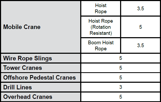
Type I must have an operating design factor of no less than 5, except where the wire rope manufacturer and the equipment manufacturer approves the design factor, in writing.
When Types II and III with an operating design factor of less than 5 are used (for non-duty cycle, non-repetitive lifts), the following requirements must be met for each lifting operation:
A qualified person must inspect the rope in accordance with § 1926.1413(a). The rope must be used only if the qualified person determines that there are no deficiencies constituting a hazard. In making this determination, more than one broken wire in any one rope lay must be considered a hazard.
Each lift made under § 1926.1414(e)(3) must be recorded in the monthly and annual inspection documents. Such prior uses must be considered by the qualified person in determining whether to use the rope again.
Rotation resistant ropes may be used as boom hoist reeving when load hoists are used as boom hoists for attachments such as luffing attachments or boom and mast attachment systems. Under these conditions, all of the following requirements must be met:
The requirements in ASME B30.5-2004 sections 5-1.3.2(a), (a)(2) through (a)(4), (b) and (d) (incorporated by reference, see § 1926.6) except that the minimum pitch diameter for sheaves used in multiple rope reeving is 18 times the nominal diameter of the rope used (instead of the value of 16 specified in section 5-1.3.2(d)).
The operating design factor for these ropes must be the total minimum breaking force of all parts of rope in the system divided by the load imposed on the rope system when supporting the static weights of the structure and the load within the equipment"s rated capacity.
Wire rope clips used in conjunction with wedge sockets must be attached to the unloaded dead end of the rope only, except that the use of devices specifically designed for dead-ending rope in a wedge socket is permitted.
Prior to cutting a wire rope, seizings must be placed on each side of the point to be cut. The length and number of seizings must be in accordance with the wire rope manufacturer"s instructions.
Wire rope is often used in slings because of its strength, durability, abrasion resistance and ability to conform to the shape of the loads on which it is used. In addition, wire rope slings are able to lift hot materials.
Wire rope used in slings can be made of ropes with either Independent Wire Rope Core (IWRC) or a fiber-core. It should be noted that a sling manufactured with a fiber-core is usually more flexible but is less resistant to environmental damage. Conversely, a core that is made of a wire rope strand tends to have greater strength and is more resistant to heat damage.
Wire rope may be manufactured using different rope lays. The lay of a wire rope describes the direction the wires and strands are twisted during the construction of the rope. Most wire rope is right lay, regular lay. This type of rope has the widest range of applications. Wire rope slings may be made of other wire rope lays at the recommendation of the sling manufacturer or a qualified person.
Wire rope slings are made from various grades of wire rope, but the most common grades in use are Extra Improved Plow Steel (EIPS) and Extra Extra Improved Plow Steel (EEIPS). These wire ropes are manufactured and tested in accordance with ASTM guidelines. If other grades of wire rope are used, use them in accordance with the manufacturer"s recommendations and guidance.
When selecting a wire rope sling to give the best service, consider four characteristics: strength, ability to bend without distortion, ability to withstand abrasive wear, and ability to withstand abuse.
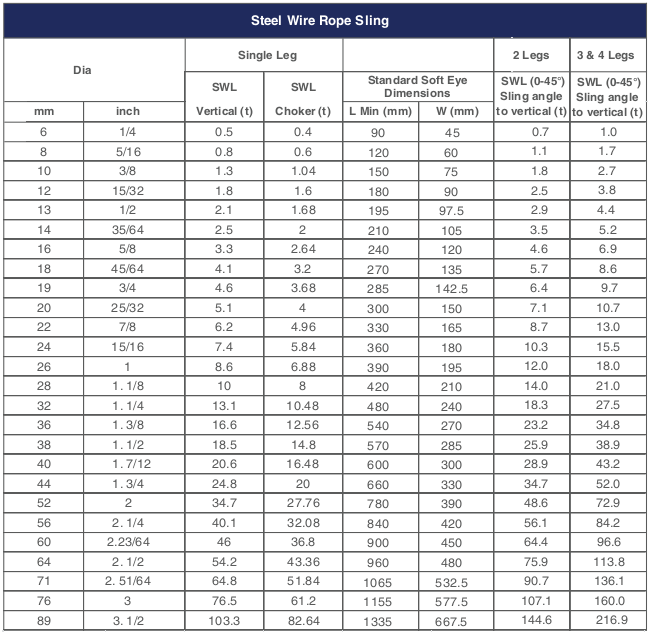
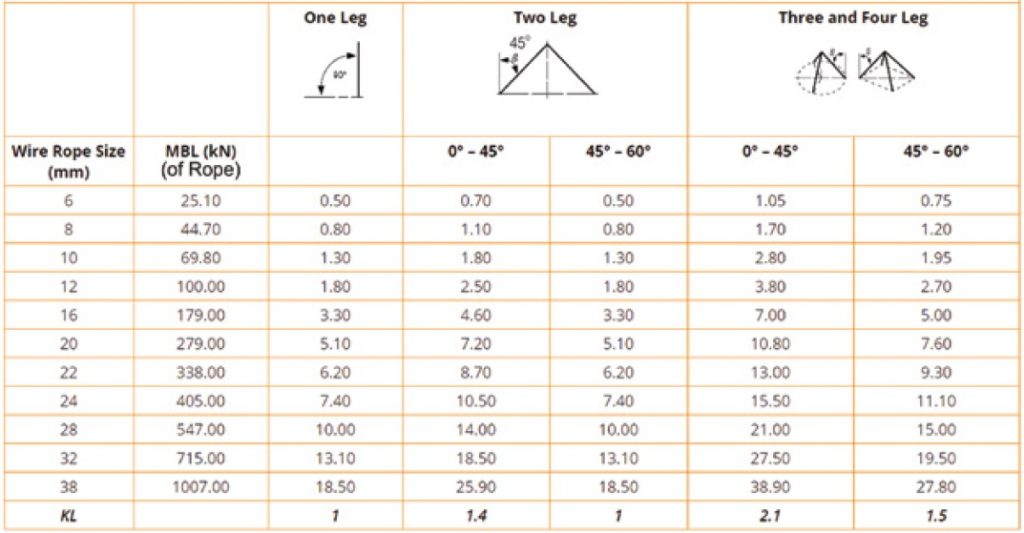
Rated loads (capacities) for single-leg vertical, choker, basket hitches, and two-, three-, and four-leg bridle slings for specific grades of wire rope slings are as shown in Tables 7 through 15.
Rated loads for a sling in a choker hitch are the values shown in Table 7, 9, 11, 13, 14, or 15, provided that the angle of the choke is 120 degrees or more (Fig. 2). Use the values in Fig. 2 or those from the sling manufacturer or a qualified person for angles of choke less than 120 degrees.
Ensure that slings made of rope with 6×19 and 6x37 classifications and cable slings have a minimum clear length of rope 10 times the component rope diameter between splices, sleeves, or end fittings unless approved by a qualified person,
Ensure that braided slings have a minimum clear length of rope 40 times the component rope diameter between the loops or end fittings unless approved by a qualified person,
Ensure that grommets and endless slings have a minimum circumferential length of 96 times the body diameter of the grommet or endless sling unless approved by a qualified person, and
Perform welding of handles or other accessories to end attachments, except covers to thimbles, before assembly of the sling. Ensure that welded end attachments are proof tested by the manufacturer or a qualified person. Retain the certificates of proof test and make them available for examination.
Do not use wire rope clips to fabricate wire rope slings, except where the application precludes the use of prefabricated slings and where the sling is designed for the specific application by a qualified person,
Although OSHA"s sling standard does not require you to make and maintain records of inspections, the ASME standard contains provisions on inspection records.[3]
Use damaged slings only after they are repaired, reconditioned, and proof tested by the sling manufacturer or a qualified person using the following criteria:
Ensure that wire rope slings have suitable characteristics for the type of load, hitch, and environment in which they will be used and that they are not used with loads in excess of the rated load capacities described in the appropriate tables. When D/d ratios (Fig. 4) are smaller than those listed in the tables, consult the sling manufacturer. Follow other safe operating practices, including:
Ensure that multiple-leg slings are selected according to Tables 7 through 15 when used at the specific angles given in the tables. Ensure that operations at other angles are limited to the rated load of the next lower angle given in the tables or calculated by a qualified person,
When D/d ratios (see Fig. 6) smaller than those cited in the tables are necessary, ensure that the rated load of the sling is decreased. Consult the sling manufacturer for specific data or refer to the WRTB (Wire Rope Technical Board) Wire Rope Sling Users Manual, and
Ensure that all portions of the human body are kept away from the areas between the sling and the load and between the sling and the crane or hoist hook,
When using a basket hitch, ensure that the legs of the sling contain or support the load from the sides, above the center of gravity, so that the load remains under control,
Ensure that the load applied to the hook is centered in the base (bowl) of the hook to prevent point loading on the hook, unless the hook is designed for point loading,
Before initial use, ensure that all new swaged-socket, poured-socket, turnback-eye, mechanical joint grommets, and endless wire rope slings are proof tested by the sling manufacturer or a qualified person.
Permanently remove from service fiber-core wire rope slings of any grade if they are exposed to temperatures in excess of 180 degrees F (82 degrees C).
Follow the recommendations of the sling manufacturer when you use metallic-core wire rope slings of any grade at temperatures above 400 degrees F (204 degrees C) or below minus 40 degrees F (minus 40 degrees C).

SWL, NWL, MBS — all of the acronyms can get very confusing. Don’t fret – we’re here to clear things up when it comes to safe working load limits and the terms associated with it.
Safe Working Load (SWL) sometimes stated as the Normal Working Load (NWL) is the mass or force that a piece of lifting equipment, lifting device or accessory can safely utilize to lift, suspend, or lower a mass without fear of breaking. Usually marked on the equipment by the manufacturer and is often 1/5 of the Minimum Breaking Strength (MBS) although other fractions may be used such as 1/4, 1/6 and 1/10.[1][2][3]
Other synonyms include Working Load Limit (WLL), which is the maximum working load designed by the manufacturer. This load represents a force that is much less than that required to make the lifting equipment fail or yield, also known as the Minimum Breaking Load (MBL). SWL or WLL are calculated by dividing MBL by a safety factor (SF). An example of this would be a chain that has a MBL of 2000 lbf (8.89 kN) would have a SWL or WLL of 400 lbf (1.78 kN) if a safety factor of 5 (5:1, 5 to 1, or 1/5) is used.
Here at Industrial Rope Supply, we are not only committed to providing you with a quality product, but also with all the information needed to insure safety comes first on every job. Have safety questions on a product purchased from us? Contact us today and we’ll be happy to talk you through and/or provide you with the safety materials needed.

The LKING STEEL LIMITED 6 x 37 IWRC (independent wire rope core) single-leg wire rope sling has eye-and-eye endings and a mechanical splice for lifting loads with vertical, choker, or basket configurations in general industry applications. The 6 x 37 IWRC construction contains six strands of wire rope with approximately 37 wires per strand wrapped around a separate 7 X 7 wire rope, which has seven strands with seven wires per strand, in the center of the sling. This construction provides more flexibility than a 6 x 7 or 6 x 19 wire rope sling. The wire rope construction has more abrasion and heat resistance than a web sling. This eye-and-eye sling has an eye, or loop, on both ends, and can be used with vertical, choker, and basket lifting configurations. The eyes are secured with a mechanical (also called Flemish) splice that is stronger than a hand splice. This sling has a minimum D/d ratio of 25 and meets American Society of Mechanical Engineers (ASME) specification B30.9 and Occupational Safety and Health Administration (OSHA) specification 1910.184.
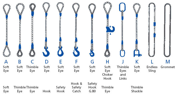
Slings are used to lift heavy objects for industrial applications. Types of slings include web slings, wire rope slings, chain slings, and mesh slings. The appropriate type of sling for an application depends on the strength-to-weight ratio, flexibility and resistance to bending, resistance to abrasion and cutting, resistance to crushing, resistance to stretching, and resistance to high temperatures and other environmental stressors. Slings have one, two, three, or four legs; or a continuous loop of webbing or wire rope. Legs are support branches that extend from a single point at the top of the sling to the item being lifted so the weight of the load is distributed evenly among the branches. Slings have eyes (loops) or alloy steel fittings on the ends.
A vertical lifting configuration connects a crane hook directly to a load with a single, vertical sling, usually by means of a hook. In a choker configuration, the sling wraps entirely around the load, and one loop passes through the other to form a slip noose, or choker. In a basket configuration, the sling passes under the load and both ends of the sling connect to the crane hook. Load capacity is the maximum weight to be lifted in a vertical configuration. The capacity in a choker configuration is approximately equal to the vertical capacity times 0.8. The capacity in a basket configuration, with sling ends at a 90-degree angle, is approximately equal to twice the vertical capacity. Load capacity in a basket configuration decreases if the angle of the sling is less than 90 degrees. For example, a sling with a capacity of 2,000 lb. in a vertical configuration will have an approximate capacity of (2,000)(0.8)=1,600 lb. in a choker configuration and an approximate capacity of (2,000)(2)=4,000 lb. in a basket configuration, if the sling ends are at a 90-degree angle to the load. A wire rope sling"s capacity in a basket configuration applies only when the configuration meets the sling"s minimum D/d ratio, which is the ratio of the diameter of the rope"s curve around the load (D) to the diameter of the sling (d). If the minimum D/d ratio is not met, the capacity of the sling is decreased.
LKING STEEL LIMITED Lifting Technologies manufactures lifting solutions including slings, cranes, and hoists. Founded in 1967, the company is headquartered in Shanghai, China.
B) if the 2legswire rope sling, the hanging points should be on both sides of the goods and the hooks are above the center of gravity of the suspended objects.
C) if it is three legs or four legs wire rope sling, the hanger must be proportioned on the plane around the cargo and the hook is located directly above the center of gravity of the suspended object.
SWL, NWL, MBS — all of the acronyms can get very confusing. Don’t fret – we’re here to clear things up when it comes to safe working load limits and the terms associated with it.
Safe Working Load (SWL) sometimes stated as the Normal Working Load (NWL) is the mass or force that a piece of lifting equipment, lifting device or accessory can safely utilize to lift, suspend, or lower a mass without fear of breaking. Usually marked on the equipment by the manufacturer and is often 1/5 of the Minimum Breaking Strength (MBS) although other fractions may be used such as 1/4, 1/6 and 1/10.[1][2][3]
Other synonyms include Working Load Limit (WLL), which is the maximum working load designed by the manufacturer. This load represents a force that is much less than that required to make the lifting equipment fail or yield, also known as the Minimum Breaking Load (MBL). SWL or WLL are calculated by dividing MBL by a safety factor (SF). An example of this would be a chain that has a MBL of 2000 lbf (8.89 kN) would have a SWL or WLL of 400 lbf (1.78 kN) if a safety factor of 5 (5:1, 5 to 1, or 1/5) is used.
Here at Industrial Rope Supply, we are not only committed to providing you with a quality product, but also with all the information needed to insure safety comes first on every job. Have safety questions on a product purchased from us? Contact us today and we’ll be happy to talk you through and/or provide you with the safety materials needed.

Safe Working Load (SWL) is the limiting safety factor to lift and carry any load safely. It must be clearly marked on any lifting device (hoist, lifts, lifting machines, and lifting tackles).
“No lifting machine and no chain, rope or lifting tackle shall, except for the purpose of the test, be loaded beyond the safe working load which shall be plainly marked and duly entered in the prescribed register, and where this is not practicable, a table showing the safe working loads of every kind and size of lifting machine or chain, rope or lifting tackle in use shall be displayed in prominent positions on the premises”
Where the safe working load may be varied by the raising or lowering of the jib, a table indicating the SWL at the corresponding indication of the jib or corresponding radii of the load shall be attached with the jib-crane.
A table showing the SWL (Safe Working Load) of every kind and size of chain, rope, or lifting tackle in use, and in case of multiple slings, the SWLat different angles of the legs, shall be posted in the storeroom.
Lifting equipment should have a tally plate indicating the Safe Working Load. The tally plate also indicates the identification number which can be mentioned in the test certificate held by the user. It should also indicate the date of the last inspection.
Safe Working Load (SWL) of any mobile crane depends on the operator’s skill, condition of the ground, boom length, the radius of rotation while lifting the load, the inclination of the boom to the vertical and outrigger blocked or free.
Safe Working Load is generally tabulated in the load chart of the crane. Sometimes, it is de-rated(decreased) due to defect in welding, bend in angle, bracing, etc., and condition of clutch, brake, etc. Modern cranes give a digital display of SWL, angle indicator, boom limit switch, and alarm for exceeding load.
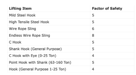
The factor of the safety (Safety Factor) of fiber ropes varies from 6 to 12 mm depending on the conditions of use. fiber rope less than 12 mm dia should not be used for a sling or apart of a lifting appliance. Their factor of safety (FS) varies with diameter. The factor of Safety for the hook, wire rope sling, chain, fiber rope, and belt are given in the table below:
Proof testing is the application of a load greater than the SWL (Safe Working Load) to detect defective workmanship, faulty weld or other inherent weaknesses. It is not a means to assess the SWLwhich should only be done by calculations and checked where necessary by suitable tests on samples.
The proof test is required as a part of ‘thorough examination’ u/r 60(1) of GFRand no lifting machine or tackle should be used for the first time without this proof test.
In general, the proof load applied to chains, rings, hooks, shackles, and similar gear is twice the SWL. It should be just under the yield stress for the material.
Chain, ring, hook, shackles, swivel, sling, individual components of the hoist, wire rope, chain, pulleys, hooks, eye bolts, pins, axles, bearings, turnbuckles & ringing screws.2 SWL
After the above proof test, the parts are to be examined thoroughly by a competent person for signs of cracks, fatigue, deformation, permanent stretch, etc.
Examine slings for wear, fatigue, crushed or broken wires, kinking, ballooning or "bird-caging", heat damage, etc. Check both before and after using slings to detect any damage or defects. See Hoist wire rope for more inspection tips.
All wire rope slings shall be tagged with name or trademark of manufacture, rated loads for the types of hitches used and the angle upon which it is based and the diameter or size.
Any sling that is not standard, an in-house break test shall be performed and the results recorded and placed in the proper binder. If the test proves unsatisfactory, the sling shall not be manufactured until such time that necessary changes are made and the assembley meets all requirements.
Before being released to the customer, the fabricator and second inspector shall sign The New Product Fabrication Form that they have met these standards in the manufacturing, testing and packaging process.


 8613371530291