
what is wire rope sling free sample
Counter weight or weight balance concrete blocks or bricks as part of suspended wire rope platform for facade works on high multistorey buildings many blocks with metal handles
Wire ropes are essential for safety purposes on construction sites and industrial workplaces. They are used to secure and transport extremely heavy pieces of equipment – so they must be strong enough to withstand substantial loads. This is why the wire rope safety factor is crucial.
You may have heard that it is always recommended to use wire ropes or slings with a higher breaking strength than the actual load. For instance, say that you need to move 50,000 lbs. with an overhead crane. You should generally use equipment with a working load limit that is rated for weight at least five times higher – or 250,000 lbs. in this case.
This recommendation is all thanks to the wire rope safety factor. This calculation is designed to help you determine important numbers, such as the minimum breaking strength and the working load limit of a wire rope.
The safety factor is a measurement of how strong of a force a wire rope can withstand before it breaks. It is commonly stated as a ratio, such as 5:1. This means that the wire rope can hold five times their Safe Work Load (SWL) before it will break.
So, if a 5:1 wire rope’s SWL is 10,000 lbs., the safety factor is 50,000 lbs. However, you would never want to place a load near 50,000 lbs. for wire rope safety reasons.
The safety factor rating of a wire rope is the calculation of the Minimum Break Strength (MBS) or the Minimum Breaking Load (MBL) compared to the highest absolute maximum load limit. It is crucial to use a wire rope with a high ratio to account for factors that could influence the weight of the load.
The Safe Working Load (SWL) is a measurement that is required by law to be clearly marked on all lifting devices – including hoists, lifting machines, and tackles. However, this is not visibly listed on wire ropes, so it is important to understand what this term means and how to calculate it.
The safe working load will change depending on the diameter of the wire rope and its weight per foot. Of course, the smaller the wire rope is, the lower its SWL will be. The SWL also changes depending on the safety factor ratio.
The margin of safety for wire ropes accounts for any unexpected extra loads to ensure the utmost safety for everyone involved. Every year there aredue to overhead crane accidents. Many of these deaths occur when a heavy load is dropped because the weight load limit was not properly calculated and the wire rope broke or slipped.
The margin of safety is a hazard control calculation that essentially accounts for worst-case scenarios. For instance, what if a strong gust of wind were to blow while a crane was lifting a load? Or what if the brakes slipped and the load dropped several feet unexpectedly? This is certainly a wire rope safety factor that must be considered.
Themargin of safety(also referred to as the factor of safety) measures the ultimate load or stress divided by theallowablestress. This helps to account for the applied tensile forces and stress thatcouldbe applied to the rope, causing it to inch closer to the breaking strength limit.
A proof test must be conducted on a wire rope or any other piece of rigging equipment before it is used for the first time.that a sample of a wire rope must be tested to ensure that it can safely hold one-fifth of the breaking load limit. The proof test ensures that the wire rope is not defective and can withstand the minimum weight load limit.
First, the wire rope and other lifting accessories (such as hooks or slings) are set up as needed for the particular task. Then weight or force is slowly added until it reaches the maximum allowable working load limit.
Some wire rope distributors will conduct proof loading tests before you purchase them. Be sure to investigate the criteria of these tests before purchasing, as some testing factors may need to be changed depending on your requirements.
When purchasing wire ropes for overhead lifting or other heavy-duty applications, understanding the safety dynamics and limits is critical. These terms can get confusing, but all of thesefactors serve an important purpose.
Our company has served as a wire rope distributor and industrial hardware supplier for many years. We know all there is to know about safety factors. We will help you find the exact wire ropes that will meet your requirements, no matter what project you have in mind.
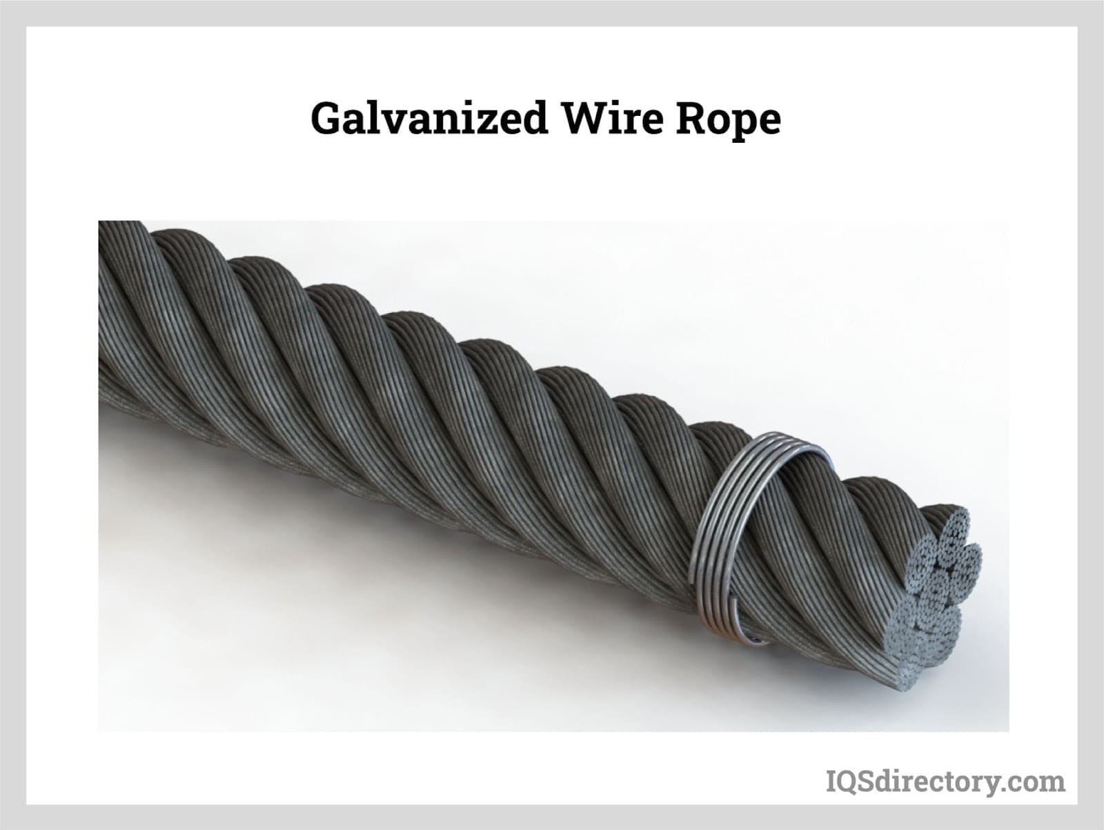
Nantong Fasten Metals Products Co., LTD is located in the coastal open city—Nantong which is in the lower area of the Yangtze River. We are a professional corporation which produces a variety of standards and types of galvanized steel wire rope, ungalvanized steel wire rope, steel-wire, stranded wire and spring steel wire. Our products mainly exported to Southeast Asia, the United States, Europe, the Middle East, Africa and other countries.

Wire rope is often used in slings because of its strength, durability, abrasion resistance and ability to conform to the shape of the loads on which it is used. In addition, wire rope slings are able to lift hot materials.
Wire rope used in slings can be made of ropes with either Independent Wire Rope Core (IWRC) or a fiber-core. It should be noted that a sling manufactured with a fiber-core is usually more flexible but is less resistant to environmental damage. Conversely, a core that is made of a wire rope strand tends to have greater strength and is more resistant to heat damage.
Wire rope may be manufactured using different rope lays. The lay of a wire rope describes the direction the wires and strands are twisted during the construction of the rope. Most wire rope is right lay, regular lay. This type of rope has the widest range of applications. Wire rope slings may be made of other wire rope lays at the recommendation of the sling manufacturer or a qualified person.
Wire rope slings are made from various grades of wire rope, but the most common grades in use are Extra Improved Plow Steel (EIPS) and Extra Extra Improved Plow Steel (EEIPS). These wire ropes are manufactured and tested in accordance with ASTM guidelines. If other grades of wire rope are used, use them in accordance with the manufacturer"s recommendations and guidance.
When selecting a wire rope sling to give the best service, consider four characteristics: strength, ability to bend without distortion, ability to withstand abrasive wear, and ability to withstand abuse.
Rated loads (capacities) for single-leg vertical, choker, basket hitches, and two-, three-, and four-leg bridle slings for specific grades of wire rope slings are as shown in Tables 7 through 15.
Rated loads for a sling in a choker hitch are the values shown in Table 7, 9, 11, 13, 14, or 15, provided that the angle of the choke is 120 degrees or more (Fig. 2). Use the values in Fig. 2 or those from the sling manufacturer or a qualified person for angles of choke less than 120 degrees.
Ensure that slings made of rope with 6×19 and 6x37 classifications and cable slings have a minimum clear length of rope 10 times the component rope diameter between splices, sleeves, or end fittings unless approved by a qualified person,
Ensure that braided slings have a minimum clear length of rope 40 times the component rope diameter between the loops or end fittings unless approved by a qualified person,
Ensure that grommets and endless slings have a minimum circumferential length of 96 times the body diameter of the grommet or endless sling unless approved by a qualified person, and
Perform welding of handles or other accessories to end attachments, except covers to thimbles, before assembly of the sling. Ensure that welded end attachments are proof tested by the manufacturer or a qualified person. Retain the certificates of proof test and make them available for examination.
Do not use wire rope clips to fabricate wire rope slings, except where the application precludes the use of prefabricated slings and where the sling is designed for the specific application by a qualified person,
Although OSHA"s sling standard does not require you to make and maintain records of inspections, the ASME standard contains provisions on inspection records.[3]
Use damaged slings only after they are repaired, reconditioned, and proof tested by the sling manufacturer or a qualified person using the following criteria:
Ensure that wire rope slings have suitable characteristics for the type of load, hitch, and environment in which they will be used and that they are not used with loads in excess of the rated load capacities described in the appropriate tables. When D/d ratios (Fig. 4) are smaller than those listed in the tables, consult the sling manufacturer. Follow other safe operating practices, including:
Ensure that multiple-leg slings are selected according to Tables 7 through 15 when used at the specific angles given in the tables. Ensure that operations at other angles are limited to the rated load of the next lower angle given in the tables or calculated by a qualified person,
When D/d ratios (see Fig. 6) smaller than those cited in the tables are necessary, ensure that the rated load of the sling is decreased. Consult the sling manufacturer for specific data or refer to the WRTB (Wire Rope Technical Board) Wire Rope Sling Users Manual, and
Ensure that all portions of the human body are kept away from the areas between the sling and the load and between the sling and the crane or hoist hook,
When using a basket hitch, ensure that the legs of the sling contain or support the load from the sides, above the center of gravity, so that the load remains under control,
Ensure that the load applied to the hook is centered in the base (bowl) of the hook to prevent point loading on the hook, unless the hook is designed for point loading,
Before initial use, ensure that all new swaged-socket, poured-socket, turnback-eye, mechanical joint grommets, and endless wire rope slings are proof tested by the sling manufacturer or a qualified person.
Permanently remove from service fiber-core wire rope slings of any grade if they are exposed to temperatures in excess of 180 degrees F (82 degrees C).
Follow the recommendations of the sling manufacturer when you use metallic-core wire rope slings of any grade at temperatures above 400 degrees F (204 degrees C) or below minus 40 degrees F (minus 40 degrees C).

Wire rope slings are strong, efficient, and reliable accessories in the material handling industry. Wire rope functions as a excellent sling material in applications where a combination of strength and abrasion are necessary. Wire rope slings are available in an array of configurations to fit almost any application.
Wire rope is a machine composed of a number of precise, moving parts, designed and manufactured to bear a very definite relation to one another. In fact, some wire ropes contain more moving parts than many complicated mechanisms. For example, a 6-strand rope with 49-wire strands laid around an independent wire rope core contains a total of 343 individual wires. All of these wires must work together and move with respect to one another if the rope is to have the flexibility necessary for successful operation.
Employers must use only wire-rope slings that have permanently affixed and legible identification markings as prescribed by the manufacturer, and that indicate the recommended safe working load for the type(s) of hitch(es) used, the angle upon which it is based, and the number of legs if more than one.
Cable laid and 6 × 19 and 6 × 37 slings shall have a minimum clear length of wire rope 10 times the component rope diameter between splices, sleeves or end fittings.
Fiber core wire rope slings of all grades shall be permanently removed from service if they are exposed to temperatures in excess of 200 °F. When nonfiber core wire rope slings of any grade are used at temperatures above 400 °F or below minus 60 °F, recommendations of the sling manufacturer regarding use at that temperature shall be followed.
Hooks that have been opened more than 15 percent of the normal throat opening measured at the narrowest point or twisted more than 10 degrees from the plane of the unbent hook.
Wire rope slings are strong, efficient, and reliable accessories in the material handling industry. Wire rope functions as a excellent sling material in applications where a combination of strength and abrasion are necessary. Wire rope slings are available in an array of configurations to fit almost any application.
Wire rope is a machine composed of a number of precise, moving parts, designed and manufactured to bear a very definite relation to one another. In fact, some wire ropes contain more moving parts than many complicated mechanisms. For example, a 6-strand rope with 49-wire strands laid around an independent wire rope core contains a total of 343 individual wires. All of these wires must work together and move with respect to one another if the rope is to have the flexibility necessary for successful operation.

Wire rope slings are extremely strong and an excellent choice for heavy duty jobs involving not only lifting, but also hoisting, towing, or anchoring loads. The fabrication of wire slings also offers excellent abrasion-resistance and heat resistance so it can be used in extreme conditions and temperatures. Its pliable design can conform to the shape of a load for a more secure application.
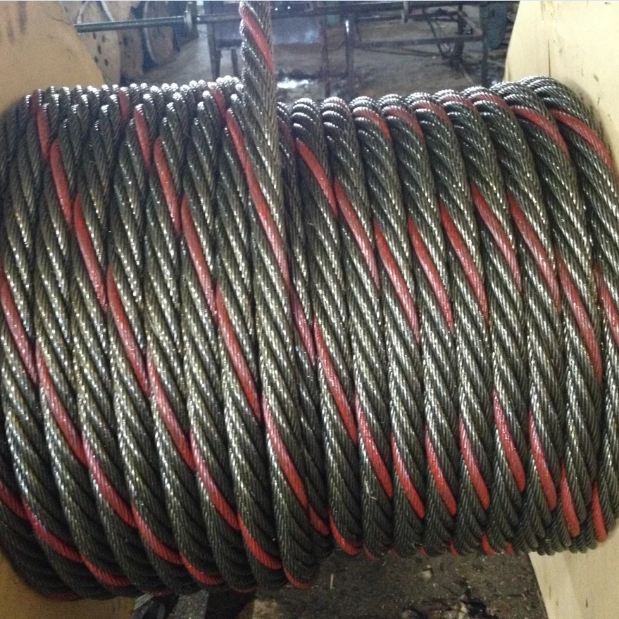
Wire rope slings are manufactured in a variety of configurations, with 6x19 and 6x36, being two of the most common. The numbers represent the number of wires making up the strand and the number of strands wrapped around the core. For example, a 6x19 indicates that there are 19 wires making up a strand, and 6 strands are wrapped around the core.
Each steel wire rope configuration will offer different benefits and will be better suited to certain applications. In general, a smaller number of large outer wires offers better wear and corrosion resistance, while a larger number of small wires provides a better level of flexibility and fatigue resistance.
We offer steel wire rope slings in both 6x19 and 6x36 configurations, depending on the diameter of the wire rope. All are in a bright (unfinished) wire rope, but other configurations are available by request. Our cable laid slings are manufactured in a 7x7x7 galvanized wire rope (composed of 7 strands of 7x7 cables), which make them extremely flexible and useful for more specialized applications.
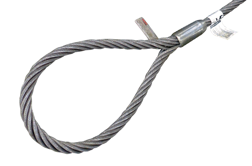
The eye loops on our sling cable are created with a Flemish splice, which is a mechanical splice where the rope cable is separated into two parts (one part has three strands, the other part has the remaining three strands plus the core), then re-laid back in the opposite direction to form the loop. The ends are then secured with a carbon steel sleeve around the entire area. Flemish splices offer the most efficient use of capacity.
The core of the wire rope used in cable slings can be made of several different materials, including steel or natural fibers. Our steel wire rope slings are made with Extra Improved Plowed Steel (EIPS) around an Independent Wire Rope Core (IWRC) for the ultimate in strength and durability.
Our categories of wire rope slings are broken down by number of legs, hardware, and the diameter of the wire rope. Each wire sling is made to order, so custom slings are also always an option if you don"t see what you"re looking for here.
We offer a wide selection of both domestic wire rope slings and import wire rope slings online, with additional options and customization available by calling our sales team.
Import slings are a more cost-effective choice yet offer the same wire rope strength and working load limits as our domestic slings. Our imported slings also feature sleeve components from Crosby. Wire rope slings we import are also available in custom configurations.
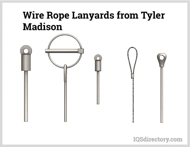
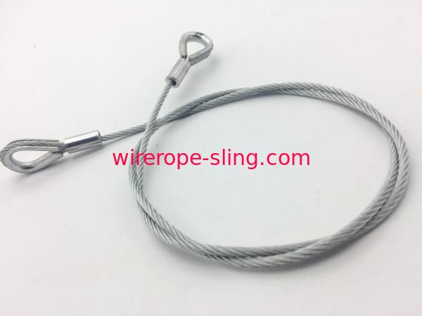
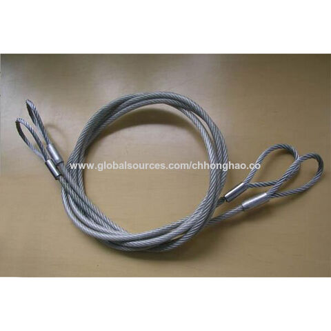
Sometimes called eye & eye slings because of an oval "eye" at each end, these 1 leg cable slings are rugged and reliable and a very popular choice among wire slings. The eyes are formed using a Flemish eye splice and secured with a carbon steel sleeve.
Single leg cable slings are available in a variety of styles: Eye & Thimble, Thimble & Thimble, Eye & Hook, Eye & Eye, Sliding Choker, and Cable Laid.
Also known as a 2 leg bridle sling, this sling offers increased versatility over a sling with just a single leg. Manufactured with a Flemish eye that"s spliced with a carbon steel sleeve; end options range from a latched eye hook to a simple eye design. Our 2 leg wire rope slings are available in seven different diameters of rope. Custom options are also an option.
Our 3 leg wire rope slings are also known in the industry as a 3 leg bridle sling. Each is manufactured with a Flemish eye that"s spliced with a carbon steel sleeve for the ultimate in safety and strength. End options include latched eye hooks, eyes equipped with thimbles, and more, as customized options are always available. Our 3 leg wire rope slings are available in seven different diameters of rope.
A 4 leg bridle sling offers the ultimate in versatility. Also known in the industry as wire rope 4 leg bridle slings, ours are manufactured with a Flemish eye that"s spliced with a carbon steel sleeve for an extra measure of security. And because legs can be fitted with hardware of your choosing, from simple eye formations to heavy duty hooks, it results in a sling customized to your exact application needs. Our 4 leg wire rope slings are available in six different diameters of rope.
Braided wire rope slings are formed when multiple wire ropes are braided continuously to form the body of the sling and the eye/eyes into a single fabricated sling. Braided wire slings are excellent for higher capacity lifts and can be either round or flat. One benefit of a braided sling is its ability to conform snugly to a load that"s in a choker hitch. Because of the braided design, they also are better resistant to kinking.
Our braided wire rope slings are made in the USA and available in a variety of configurations, including a 3-part braid, 6-part braid, 8-part braid, and 9-part braid. Several style options are also available, including standard eyes, thimble eyes, and more, to create a customized braided wire rope sling to your specifications.
Wire rope bridles are measured by the length of the sling leg plus the end hook. The length of the oblong master should not be included in the overall measurement.
Our slings are available in a variety of lengths, but can also be customized to any length you need. Give our sales team a call for more information or to place a custom order.
"Slings in contact with edges, corners, protrusions, or abrasive surfaces shall be protected with a material of sufficient strength, thickness, and construction to prevent damage."- ASME B30.9 (2021) 9-5.10.4(d)
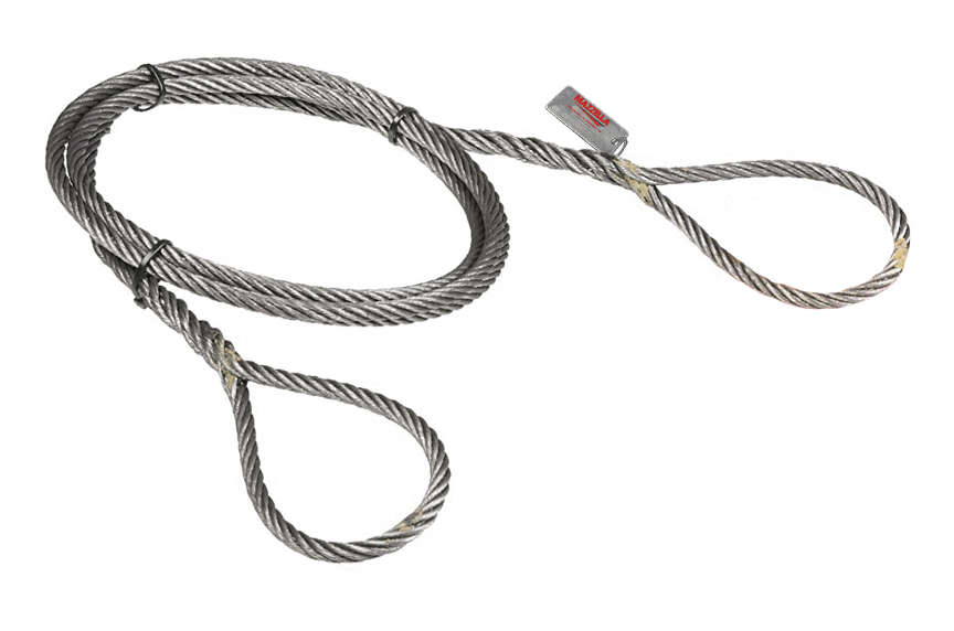
All of our slings are inspected, certified and tagged with metal tags displaying rated capacities by hitch types and angles; diameter or size; and name/trademark of the manufacturer.
Proof testing certificates can be supplied with your order for a nominal fee and must be requested at the time of order. Proof tests are performed in the factory where the sling is pull tested to 2x the vertical rating and officially recorded as proof for governing bodies. During the standard manufacturing process, only random slings during a production run are tested for compliance; in order to provide proof testing certificates with your order, every sling must be pull tested at the time of manufacture.
If steel wire rope slings are not the best choice for your application, we also offer chain slings, nylon lifting slings, and polyester round slings in a wide range of styles and capacities. As with all of our lifting slings, customization is always an option.
If you need help selecting a sling, check out our How to Choose a Lifting Sling page or call our product specialists . They"ll be happy to any answer questions you may have and can even place a custom order if needed.

Employers must use only wire-rope slings that have permanently affixed and legible identification markings as prescribed by the manufacturer, and that indicate the recommended safe working load for the type(s) of hitch(es) used, the angle upon which it is based, and the number of legs if more than one.
Cable laid and 6 × 19 and 6 × 37 slings shall have a minimum clear length of wire rope 10 times the component rope diameter between splices, sleeves or end fittings.
Fiber core wire rope slings of all grades shall be permanently removed from service if they are exposed to temperatures in excess of 200 °F. When nonfiber core wire rope slings of any grade are used at temperatures above 400 °F or below minus 60 °F, recommendations of the sling manufacturer regarding use at that temperature shall be followed.
Hooks that have been opened more than 15 percent of the normal throat opening measured at the narrowest point or twisted more than 10 degrees from the plane of the unbent hook.
In stricter senses, the term wire rope refers to a diameter larger than 9.5 mm (3⁄8 in), with smaller gauges designated cable or cords.wrought iron wires were used, but today steel is the main material used for wire ropes.
Historically, wire rope evolved from wrought iron chains, which had a record of mechanical failure. While flaws in chain links or solid steel bars can lead to catastrophic failure, flaws in the wires making up a steel cable are less critical as the other wires easily take up the load. While friction between the individual wires and strands causes wear over the life of the rope, it also helps to compensate for minor failures in the short run.
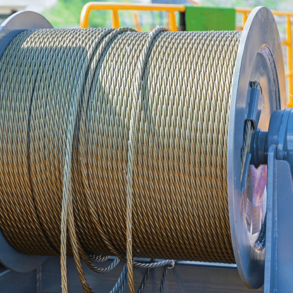
Wire ropes were developed starting with mining hoist applications in the 1830s. Wire ropes are used dynamically for lifting and hoisting in cranes and elevators, and for transmission of mechanical power. Wire rope is also used to transmit force in mechanisms, such as a Bowden cable or the control surfaces of an airplane connected to levers and pedals in the cockpit. Only aircraft cables have WSC (wire strand core). Also, aircraft cables are available in smaller diameters than wire rope. For example, aircraft cables are available in 1.2 mm (3⁄64 in) diameter while most wire ropes begin at a 6.4 mm (1⁄4 in) diameter.suspension bridges or as guy wires to support towers. An aerial tramway relies on wire rope to support and move cargo overhead.
Modern wire rope was invented by the German mining engineer Wilhelm Albert in the years between 1831 and 1834 for use in mining in the Harz Mountains in Clausthal, Lower Saxony, Germany.chains, such as had been used before.
Wilhelm Albert"s first ropes consisted of three strands consisting of four wires each. In 1840, Scotsman Robert Stirling Newall improved the process further.John A. Roebling, starting in 1841suspension bridge building. Roebling introduced a number of innovations in the design, materials and manufacture of wire rope. Ever with an ear to technology developments in mining and railroading, Josiah White and Erskine Hazard, principal ownersLehigh Coal & Navigation Company (LC&N Co.) — as they had with the first blast furnaces in the Lehigh Valley — built a Wire Rope factory in Mauch Chunk,Pennsylvania in 1848, which provided lift cables for the Ashley Planes project, then the back track planes of the Summit Hill & Mauch Chunk Railroad, improving its attractiveness as a premier tourism destination, and vastly improving the throughput of the coal capacity since return of cars dropped from nearly four hours to less than 20 minutes. The decades were witness to a burgeoning increase in deep shaft mining in both Europe and North America as surface mineral deposits were exhausted and miners had to chase layers along inclined layers. The era was early in railroad development and steam engines lacked sufficient tractive effort to climb steep slopes, so incline plane railways were common. This pushed development of cable hoists rapidly in the United States as surface deposits in the Anthracite Coal Region north and south dove deeper every year, and even the rich deposits in the Panther Creek Valley required LC&N Co. to drive their first shafts into lower slopes beginning Lansford and its Schuylkill County twin-town Coaldale.
The German engineering firm of Adolf Bleichert & Co. was founded in 1874 and began to build bicable aerial tramways for mining in the Ruhr Valley. With important patents, and dozens of working systems in Europe, Bleichert dominated the global industry, later licensing its designs and manufacturing techniques to Trenton Iron Works, New Jersey, USA which built systems across America. Adolf Bleichert & Co. went on to build hundreds of aerial tramways around the world: from Alaska to Argentina, Australia and Spitsbergen. The Bleichert company also built hundreds of aerial tramways for both the Imperial German Army and the Wehrmacht.
In the last half of the 19th century, wire rope systems were used as a means of transmitting mechanical powercable cars. Wire rope systems cost one-tenth as much and had lower friction losses than line shafts. Because of these advantages, wire rope systems were used to transmit power for a distance of a few miles or kilometers.
Steel wires for wire ropes are normally made of non-alloy carbon steel with a carbon content of 0.4 to 0.95%. The very high strength of the rope wires enables wire ropes to support large tensile forces and to run over sheaves with relatively small diameters.
In the mostly used parallel lay strands, the lay length of all the wire layers is equal and the wires of any two superimposed layers are parallel, resulting in linear contact. The wire of the outer layer is supported by two wires of the inner layer. These wires are neighbors along the whole length of the strand. Parallel lay strands are made in one operation. The endurance of wire ropes with this kind of strand is always much greater than of those (seldom used) with cross lay strands. Parallel lay strands with two wire layers have the construction Filler, Seale or Warrington.
In principle, spiral ropes are round strands as they have an assembly of layers of wires laid helically over a centre with at least one layer of wires being laid in the opposite direction to that of the outer layer. Spiral ropes can be dimensioned in such a way that they are non-rotating which means that under tension the rope torque is nearly zero. The open spiral rope consists only of round wires. The half-locked coil rope and the full-locked coil rope always have a centre made of round wires. The locked coil ropes have one or more outer layers of profile wires. They have the advantage that their construction prevents the penetration of dirt and water to a greater extent and it also protects them from loss of lubricant. In addition, they have one further very important advantage as the ends of a broken outer wire cannot leave the rope if it has the proper dimensions.
Stranded ropes are an assembly of several strands laid helically in one or more layers around a core. This core can be one of three types. The first is a fiber core, made up of synthetic material or natural fibers like sisal. Synthetic fibers are stronger and more uniform but cannot absorb much lubricant. Natural fibers can absorb up to 15% of their weight in lubricant and so protect the inner wires much better from corrosion than synthetic fibers do. Fiber cores are the most flexible and elastic, but have the downside of getting crushed easily. The second type, wire strand core, is made up of one additional strand of wire, and is typically used for suspension. The third type is independent wire rope core (IWRC), which is the most durable in all types of environments.ordinary lay rope if the lay direction of the wires in the outer strands is in the opposite direction to the lay of the outer strands themselves. If both the wires in the outer strands and the outer strands themselves have the same lay direction, the rope is called a lang lay rope (from Dutch langslag contrary to kruisslag,Regular lay means the individual wires were wrapped around the centers in one direction and the strands were wrapped around the core in the opposite direction.
Multi-strand ropes are all more or less resistant to rotation and have at least two layers of strands laid helically around a centre. The direction of the outer strands is opposite to that of the underlying strand layers. Ropes with three strand layers can be nearly non-rotating. Ropes with two strand layers are mostly only low-rotating.
Stationary ropes, stay ropes (spiral ropes, mostly full-locked) have to carry tensile forces and are therefore mainly loaded by static and fluctuating tensile stresses. Ropes used for suspension are often called cables.
Track ropes (full locked ropes) have to act as rails for the rollers of cabins or other loads in aerial ropeways and cable cranes. In contrast to running ropes, track ropes do not take on the curvature of the rollers. Under the roller force, a so-called free bending radius of the rope occurs. This radius increases (and the bending stresses decrease) with the tensile force and decreases with the roller force.
Wire rope slings (stranded ropes) are used to harness various kinds of goods. These slings are stressed by the tensile forces but first of all by bending stresses when bent over the more or less sharp edges of the goods.
Technical regulations apply to the design of rope drives for cranes, elevators, rope ways and mining installations. Factors that are considered in design include:
Donandt force (yielding tensile force for a given bending diameter ratio D/d) - strict limit. The nominal rope tensile force S must be smaller than the Donandt force SD1.
The wire ropes are stressed by fluctuating forces, by wear, by corrosion and in seldom cases by extreme forces. The rope life is finite and the safety is only ensured by inspection for the detection of wire breaks on a reference rope length, of cross-section loss, as well as other failures so that the wire rope can be replaced before a dangerous situation occurs. Installations should be designed to facilitate the inspection of the wire ropes.
Lifting installations for passenger transportation require that a combination of several methods should be used to prevent a car from plunging downwards. Elevators must have redundant bearing ropes and a safety gear. Ropeways and mine hoistings must be permanently supervised by a responsible manager and the rope must be inspected by a magnetic method capable of detecting inner wire breaks.
The end of a wire rope tends to fray readily, and cannot be easily connected to plant and equipment. There are different ways of securing the ends of wire ropes to prevent fraying. The common and useful type of end fitting for a wire rope is to turn the end back to form a loop. The loose end is then fixed back on the wire rope. Termination efficiencies vary from about 70% for a Flemish eye alone; to nearly 90% for a Flemish eye and splice; to 100% for potted ends and swagings.
When the wire rope is terminated with a loop, there is a risk that it will bend too tightly, especially when the loop is connected to a device that concentrates the load on a relatively small area. A thimble can be installed inside the loop to preserve the natural shape of the loop, and protect the cable from pinching and abrading on the inside of the loop. The use of thimbles in loops is industry best practice. The thimble prevents the load from coming into direct contact with the wires.
A wire rope clip, sometimes called a clamp, is used to fix the loose end of the loop back to the wire rope. It usually consists of a U-bolt, a forged saddle, and two nuts. The two layers of wire rope are placed in the U-bolt. The saddle is then fitted to the bolt over the ropes (the saddle includes two holes to fit to the U-bolt). The nuts secure the arrangement in place. Two or more clips are usually used to terminate a wire rope depending on the diameter. As many as eight may be needed for a 2 in (50.8 mm) diameter rope.
The mnemonic "never saddle a dead horse" means that when installing clips, the saddle portion of the assembly is placed on the load-bearing or "live" side, not on the non-load-bearing or "dead" side of the cable. This is to protect the live or stress-bearing end of the rope against crushing and abuse. The flat bearing seat and extended prongs of the body are designed to protect the rope and are always placed against the live end.
The ends of individual strands of this eye splice used aboard a cargo ship are served with natural fiber cord after splicing to help protect seamens" hands when handling.
An eye splice may be used to terminate the loose end of a wire rope when forming a loop. The strands of the end of a wire rope are unwound a certain distance, then bent around so that the end of the unwrapped length forms an eye. The unwrapped strands are then plaited back into the wire rope, forming the loop, or an eye, called an eye splice.
A Flemish eye, or Dutch Splice, involves unwrapping three strands (the strands need to be next to each other, not alternates) of the wire and keeping them off to one side. The remaining strands are bent around, until the end of the wire meets the "V" where the unwrapping finished, to form the eye. The strands kept to one side are now re-wrapped by wrapping from the end of the wire back to the "V" of the eye. These strands are effectively rewrapped along the wire in the opposite direction to their original lay. When this type of rope splice is used specifically on wire rope, it is called a "Molly Hogan", and, by some, a "Dutch" eye instead of a "Flemish" eye.
Swaging is a method of wire rope termination that refers to the installation technique. The purpose of swaging wire rope fittings is to connect two wire rope ends together, or to otherwise terminate one end of wire rope to something else. A mechanical or hydraulic swager is used to compress and deform the fitting, creating a permanent connection. Threaded studs, ferrules, sockets, and sleeves are examples of different swaged terminations.
A wedge socket termination is useful when the fitting needs to be replaced frequently. For example, if the end of a wire rope is in a high-wear region, the rope may be periodically trimmed, requiring the termination hardware to be removed and reapplied. An example of this is on the ends of the drag ropes on a dragline. The end loop of the wire rope enters a tapered opening in the socket, wrapped around a separate component called the wedge. The arrangement is knocked in place, and load gradually eased onto the rope. As the load increases on the wire rope, the wedge become more secure, gripping the rope tighter.
Poured sockets are used to make a high strength, permanent termination; they are created by inserting the wire rope into the narrow end of a conical cavity which is oriented in-line with the intended direction of strain. The individual wires are splayed out inside the cone or "capel", and the cone is then filled with molten lead-antimony-tin (Pb80Sb15Sn5) solder or "white metal capping",zincpolyester resin compound.
Koetsier,Teun; Ceccarelli, Marc (2012). Explorations in the History of Machines and Mechanisms. Springer Publishing. p. 388. ISBN 9789400741324. Archived from the original on 31 March 2017. Retrieved 9 April 2014.
Donald Sayenga. "Modern History of Wire Rope". History of the Atlantic Cable & Submarine Telegraphy (atlantic-cable.com). Archived from the original on 3 February 2014. Retrieved 9 April 2014.
(1) Cable laid and 6 x 19 and 6 x 37 slings shall have a minimum clear length of wire rope 10 times the component rope diameter between splices, sleeves or end fittings.
(c) Safe Operating Temperatures. Fiber core wire rope slings of all grades shall be permanently removed from service if they are exposed to temperatures in excess of 200o F. When nonfiber core wire rope slings of any grade are used at temperatures above 400o F, or below minus 60o F, the sling manufacturer"s recommendations shall be followed.
(2) A prototype of each welded end attachment shall be proof tested by the manufacturer or equivalent entity to check the design and welding method at twice the rated capacity before production is started. Subsequent tests of random samples shall be made. The manufacturer or equivalent entity shall provide a certificate of such tests which the employer shall retain and make available for examination by the Division upon request.
(3) Where rope clip attachments are used, they shall be made with U-bolts on the dead or short end of the rope and the saddle on the live end. The minimum number of clips for end attachments shall be not less than indicated in manufacturer"s tables, but in no case shall be less than three for any permanent installation. Clips shall be drop-forged steel. The clips shall be spaced at a distance equal to at least six times the diameter of the rope. All clip or clamp bolts shall be kept tight after tightening while rope is under tension.
(6) Hooks that have been opened more than 15 percent of the normal throat opening measured at the narrowest point or twisted more than 10 degrees from the plane of the unbent hook.
(1) Have permanently affixed and legible identification markings as prescribed by the manufacturer, and that indicate the recommended safe working load for the type(s) of hitch(es) used, the angle upon which it is based, and the number of legs if more than one; and
2. New subsections (g)-(g)(2) filed 1-18-2012; operative 1-18-2012 pursuant to Labor Code section 142.3(a)(4)(C). Submitted to OAL for printing only pursuant to Labor Code section 142.3(a)(3) (Register 2012, No. 3)
13mm nominal diameter x 2.8tonne Working Load Limit (0-45° BETA Lifting Angle) 6X36 IWRC Grade EIPS (Tensile Strength 1960N/mm2) Galvanized Steel Wire Rope Sling Both End Mechanical Spliced with Aluminium Ferrule DIN3093 Standard Length.
FREE SHIPPING FOR PENINSULAR MALAYSIA AREA (LOCAL LORRY TRANSPORTION DUE TO HEAVY WEIGHT), EAST MALAYSIA CLIENT PLEASE CONTACT WITH US FOR FURTHER ASSISTANT.


 8613371530291