
wire rope 101 free sample
AIRCRAFT WIRE ROPE 101 WIRE ROPE Cable .......................................................1-18 Abrasion and Bending ..............................1-4 7-Strand...................................................1-16 Block Twisting .......................................1-4–5 Bridge Rope ............................................1-16BRIDGE Calculating Drum Capacity .......................1-8 Cable .................................................1-18–20 Wire Rope ...............................................1-16 Common Abuses.......................................1-5 Corrosion Resistant.................................1-17CABLE Common Causes of Failure ......................1-6 Drag.........................................................1-13 Aircraft .....................................................1-18 Conversion Tables Metric/English .............1-8 Electrical Construction ............................1-14 Alloy.........................................................1-20 Cross Sections (Illustrations) ....................1-2 Elevator ...................................................1-14 Coated.....................................................1-20 Design and Construction...........................1-1 Flattened Strand......................................1-12 Stainless Steel ........................................1-19 Glossary ............................................1-21–22 Galvanized Structural Strand ..................1-16DRAG Inspection ..................................................1-3 Galvanized Wire Strand ..........................1-12 Rope........................................................1-13 Installation .................................................1-7 General Purpose .....................................1-10 Lay of Wire Rope .....................................1-1 Herringbone ............................................1-13DRILLING AND WELL WIRE ROPE.........1-15 High Performance ...................................1-12 Lubrication.................................................1-7ELEVATOR Matching Rope to Sheave and Drum....1-7–8 Logging ...................................................1-15 Wire Rope ...............................................1-14 Matching Sheave Groove to Rope ............1-8 Marine Application...................................1-14 Nominal Strength ......................................1-3 Oil/Gas Drilling ........................................1-15FLATTENED STRAND WIRE ROPE.........1-12 Operating...................................................1-7 Plastic Filled Valley..................................1-17HERRINGBONE Physical Properties ...................................1-6 Rotation Resistant...................................1-11 Wire Rope ...............................................1-13 Rope Strength Design Factors..................1-4 Stainless..................................................1-19LOGGING Selection Guide.........................................1-6 Strand Hoist ............................................1-13 Wire Rope ...............................................1-15 Sheave Inspection.....................................1-3 Surface Mining ........................................1-13 Weights .....................................................1-3 Swage .....................................................1-15METRIC/ENGLISH Tower Power............................................1-11 What Wire Rope Is... .................................1-1 Conversion Tables .....................................1-8 Tramway ..................................................1-14 Wire Grades ..............................................1-1MINING AND EXCAVATION WIRE ROPE 1-13 Underground Mining................................1-14MINING AND TRAMWAY WIRE ROPE .....1-14 Well Service ............................................1-15
ROTATION WIRE ROPE, GENERAL PURPOSE Resistant Wire Rope ...............................1-11 6 x 7 Classification ..................................1-10 6 x 19 Classification ................................1-10STAINLESS 6 x 19 Seale Steel Cable..............................................1-19 6 x 21 Filler WireSTRAND 6 x 25 Filler Wire Hoist Wire Rope ......................................1-13 6 x 26 Warrington Seale 6 x 31 Warrington SealSWAGED 6 x 36 Warrington Seale Wire Rope ...............................................1-15 6 x 37 Classification ................................1-10TOWER CRANE 6 x 41 Seale Filler Wire Wire Rope ...............................................1-11 6 x 41 Warrington Seale 6 x 49 Seale Warrington Seale
WWW.HANESSUPPLY.COM 1- A Buffalo - Headquarters: 716.826.2636 FAX: 716.826.4412 Hanes Supply of SC, Inc. Albany/NE Division: 518.438.0139 FAX: 518.438.5343 CCISCO: 843.238.1338 Rochester Division: 585.235.0160 FAX: 585.235.0229 FAX: 843.238.83371 NOTESWire Rope
1- B WWW.HANESSUPPLY.COM Buffalo - Headquarters: 716.826.2636 FAX: 716.826.4412 Hanes Supply of SC, Inc. Albany/NE Division: 518.438.0139 FAX: 518.438.5343 CCISCO: 843.238.1338 Rochester Division: 585.235.0160 FAX: 585.235.0229 FAX: 843.238.8337 Wire Rope 1 Wire Rope 101
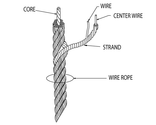
Wire RopeWhat Wire Rope Is... Wire Rope Design & ConstructionA wire rope is a piece of flexible, multi- Core Strand Wire ropes are composed of independent parts–wires, strands and cores-wired, stranded machinery made of many that continuously interact with each other during service.precision parts. Wire rope engineers design those parts in differing steel grades, finish- Usually a wire rope consists of a core es and a variety of constructions to attain the best balance of strength,member, around which a number of multi- abrasion resistance, crush resistance, bending fatigue resistance and cor-wired strands are “laid” or helically bent. rosion resistance for each application. To select the best wire rope for each application, one must know theThere are two general types of cores for required performance characteristics for the job and enough about wirewire rope - fiber cores an wire cores. The rope design to select the optimum combination of wire rope properties.fiber core may be made from natural or The following information is presented as a basic guide. Hanes Supplysynthetic fibers. The wire core can be an engineers and field service specialists are available to provide more spe-Independent Wire Rope Core (IWRC), or cific recommendations.a Strand Core (SC). Wire The purpose of the core is to provide Strand Constructionssupport and maintain the position of the Strands are designed with various combinations of wires and wire sizes toouter strands during operation. produce the desired resistance to fatigue and abrasion. Generally, a small Any number of multi-wired strands may number of large wires will be more abrasion resistant and less fatiguebe laid around the core. The most popular resistant than a large number of small wires.arrangement is six strands around thecore, as this combination gives the best Single Sizebalance. The basic strand construction has wires of the same The number of wires per strand may size wound around a center.vary from 3 to 91, with the majority of wire Wire Roperopes failing into the 7-wire, 19-wire, or37-wire strand categories.
SealeThe “lays” of Wire Rope Large outer wires with the same number of smaller inner wires around a core wire. Provides excellent abrasion“Lay” of a wire rope is simply a description of the way wires and strands resistance but less fatigue resistance. When used withare placed during construction. Right lay and left lay refer to the direction an IWRC, it offers excellent crush resistance over drums.of strands. Right lay means that the strands pass from left to right acrossthe rope. Left lay means just the opposite: strands pass from right to left. Regular lay and lang lay describe the way wires are placed within each Filler Wirestrand. Regular lay means that wires in the strands are laid opposite in Small wires fill spaces between large wires to producedirection to the lay of the strands. Lang lay means that wires are laid in crush resistance and a good balance of strength, flexibil-the same direction as the lay of the strands. ity and resistance to abrasion. Most of the wire rope used is rightlay, regular lay. This specification hasthe widest range of applications andmeets the requirements of most Warringtonequipment. In fact, other lay specifica- Outer layer of alternately large and small wires providestions are considered exceptions and good flexibility and strength but low abrasion and crushmust be requested when ordering. Left Lay REGULAR LAY resistance.Here are some exceptionsLang lay is recommended for many Many commonly used wire ropes use combinations of these basic con-excavating, construction, and mining structions.applications, including draglines, hoistlines, dredgelines and other similar Left Lay LANG LAYlines. Here"s why: Lang lay ropes aremore flexible than regular lay ropes.They also have greater wearing sur-face per wire than regular lay ropes. Where properly recommended,installed and used, lang lay ropes can Right Alternate Lay Seale Filler Wire Filler Wire Seale Warrington Seale Seale Warrington Sealebe used to greater advantage thanregular lay ropes. However, lang layropes are more susceptible to the Multiple Operationabuses of bending over small diame- One of the above strand designs may be covered withter sheaves, pinching in undersize one or more layers of uniform-sized wires.sheave grooves, crushing when wind-ing on drums, and failing due to Right Lay REGULAR LAYexcessive rotation. Left lay rope hasgreatest usage in oil fields on rod andtubing lines, blast hole rigs, and spud- Finishders where rotation of right lay rope Bright finish is suitable for most applications. Galvanized finish is availablewould loosen couplings. The rotation for corrosive environments. Plastic jacketing is also available on someof a left lay rope tightens a standard constructions.coupling. Right Lay LANG LAY Wire Grades The most common steel wire grades are: IPS (Improved Plow Steel), EIP (Extra Improved Plow Steel) and EEIP (Extra Extra Improved Plow Steel). Stainless Steels and other special grades are provided for special appli- cations. Most wire ropes are made with round wires. Both triangular and shaped wires are also used for special constructions. Generally, the higher the strength of the wire, the lower its ductility will be.
WWW.HANESSUPPLY.COM 1- 1 Buffalo - Headquarters: 716.826.2636 FAX: 716.826.4412 Hanes Supply of SC, Inc. Albany/NE Division: 518.438.0139 FAX: 518.438.5343 CCISCO: 843.238.1338 Rochester Division: 585.235.0160 FAX: 585.235.0229 FAX: 843.238.83371 Wire Rope Wire Rope 101Wire Rope
6x7 6 x 12 6 x 17 6 x 19 6 x 21 Poly Core (Marine Rope) Filler Wire 6 x 19 Seale Warrington Filler Wire
6 x 24 6 x 25 6 x 26 6 x 27* 6 x 31* 6 x 31 (Mooring Line) Filler Wire Warrington-Seale Seale Filler Wire Warrington-Seale
6 x 36 6 x 37* 6 x 41* 6 x 46 Filler Wire 6 x 36 6 x 41 Warrington-Seale Warrington Seale-Filler Wire Seale-Filler Wire Warrington-Seale
6 x 49* 6 x 49 6 x 61* 8 x 19* 8 x 25 6 x 55* Filler Wire-Seale Warrington-Seale Filler-Wire Seale Seale Filler Wire Seale-Warrington
6x8 6 x 25 6 x 30 6 x 42 (Tiller Rope) 5 x 19* 6 x 3 x 19 Style D Style B Style G (Marine Clad Rope) (Spring Lay Rope) Flattened Strand Flattened Strand Flattened Strand
1- 2 WWW.HANESSUPPLY.COM Buffalo - Headquarters: 716.826.2636 FAX: 716.826.4412 Hanes Supply of SC, Inc. Albany/NE Division: 518.438.0139 FAX: 518.438.5343 CCISCO: 843.238.1338 Rochester Division: 585.235.0160 FAX: 585.235.0229 FAX: 843.238.8337 Wire Rope 1 Wire Rope 101
Wire RopeAbrasion Resistance Fatigue Resistance Sheave Inspection ...DECREASES ...DECREASES with Smaller wires with Fewer wires Inspection of sheaves is a relatively simple, yet very vital task. A sheave groove gauge, usually obtainable from a wire rope manufacturer, is used to check the grooves in a sheave. Hold the gauge perpendicular to the ...INCREASES ...INCREASES with Larger wires surface of the groove to observe properly the groove size and contour, with More wires as in this illustration.
Allowable Rope 1/2 AllowableNominal Strengths & Weights Nominal Rope oversize Rope Oversize Dia. (in) (in) (in)Wire Rope 6 x 19 Class - 6 x 37 Class 0 - 3/4 + 1/32 + 1/64 Nominal Strength (Tons) 13/16 - 1-1/8 +3/64 +3/128 1-3/16 - 1-1/2 + 1/16 + 1/32 Dia. IPS EIPS Approx. Wt/Ft (lbs) 1-9/16 - 2-1/4 +3/32 + 3/64 (in) Fiber Core IWRC IWRC Fiber Core IWRC 2-5/16 - and larger +1/8 +1/16 3/16 1.55 1.67 – .059 .065 Photo shows new gauge and worn sheave. This new gauge 1/4 2.74 2.94 3.40 .105 .116 is designed with one-half the allowable oversize (see table). 5/16 4.26 4.58 5.27 .164 .18 Using the new gauge, when you do not see light, the sheave is OK. When you do see light under the 3/8 6.10 6.56 7.55 .236 .26 new gauge, the sheave should be replaced. 7/16 8.27 8.89 10.2 .32 .35 1/2 10.7 11.5 13.3 .42 .46 9/16 13.5 14.5 16.8 .53 .59 Sheaves Should be Checked for: 5/8 16.7 17.9 20.6 .66 .72 1. Correct groove diameter 3/4 23.8 25.6 29.4 .95 1.04 2. Roundness or contour to give proper support to the rope 7/8 32.2 34.6 39.8 1.29 1.42 1 41.8 44.9 51.7 1.68 1.85 3. Small holes, cracks, uneven surfaces, or other defects that might be 1-1/8 52.6 56.5 65.0 2.13 2.34 detrimental to the rope 1-1/4 64.6 69.4 79.9 2.63 2.89 4. Extreme deep wear 1-3/8 77.7 83.5 96. 3.18 3.50 1-1/2 92.0 98.9 114. 3.78 4.16 A sheave should also be checked to make sure it turns freely, is 1-5/8 107. 115. 132. 4.44 4.88 properly aligned, has no broken or cracked flanges, and has bearings that 1-3/4 124. 133. 153. 5.15 5.67 work properly. 1-7/8 141. 152. 174. 5.91 6.50 Drums should also be inspected for signs of wear that could damage 2 160. 172. 198. 6.72 7.39 rope. 2-1/8 179. 192. 221. 7.59 8.35 Plain-faced or smooth drums can develop grooves or impressions that 2-1/4 200. 215. 247. 8.51 9.36 prevent rope from winding properly. Repair by resurfacing the face or 2-3/8 222. 239. 274. 9.48 10.4 2-1/2 244. 262. 302. 10.5 11.6 replacing the lagging. 2-5/8 268. 288. 331. 11.6 12.8 Scrubbing will occur if the rope tends to close wind. If the tendency is to 2-3/4 292. 314. 361. 12.7 14.0 open winding, the rope will encounter abnormal abuse as the second layer 2-7/8 317. 341. 393. 13.9 15.3 forces itself down between the open wraps of the first layer on the drum. 3 – 370. 425. – 16.6 Operating with a smooth drum calls for special care. Be sure the rope is 3-1/8 – 399. 458. – 18.0 always tightly wound and thread layed on the first layer. Any loosening of 3-1/4 – 429. 492. – 19.5 the line is easily observed as the winding will be bad and the rope will be 3-3/8 – 459. 529. – 21.0 3-1/2 – 491. 564. – 22.6 coming off with a series of “bad spots.” Grooved drums should be examined for tight or corrugated grooves andAvailable galvanized at 10% lower strengths, or in equivalent strengths on special for differences in depth or pitch that could damage the second and subse-request quent layers. Worn grooves can develop extremely sharp edges that shave away small particles of steel from the rope. Correct this condition by grind-Inspection–The key to longer, safer wire rope use ing or filing a radius to replace the sharp edge. Drum flanges, as well as the starter, filler and riser strips, should beAny wire rope in use should be inspected on a regular basis. You have too checked. Excessive wear here often causes unnecessary rope abuse atmuch at stake in lives and equipment to ignore thorough examination of the change of layers and cross-over points.the rope at prescribed intervals. Other places of contact such as rollers, scrub boards, guides and end The purpose of inspection is to accurately estimate the service life and attachments should also be inspected.strength remaining in a rope so that maximum service can be had withinthe limits of safety. Results of the inspection should be recorded to provide Measure the widest diametera history of rope performance on a particular job. On most jobs wire rope Ropes and sheave grooves must be precisely fitted to each other to getmust be replaced before there is any risk of failure. A rope broken in serv- the most service out of your wire ropeice can destroy machinery and curtail production. It can also kill. dollar. Make measurement of rope Because of the great responsibility involved in ensuring safe rigging on diameter a normal part of your inspec-equipment, the person assigned to inspect should know wire rope and its tion program.operation thoroughly. Inspections should be made regularly and the results There"s only one right way to meas-recorded. ure rope diameter: use machinist"s When inspecting the rope, the condition of the drum, sheaves, guards, calipers and be sure to measure thecable clamps and other end fittings should be noted. The condition of widest diameter. These drawings com-these parts affects rope wear: any defects detected should be repaired. pare the right way with the wrong way. To ensure rope soundness between inspections, all workers should par- This method is not only useful forticipate. The operator can be most helpful by watching the ropes under his measuring the diameter of a new rope,control. If any accident involving the ropes occurs, the operator should but also for determining the amount of Right Way. Set Wrong Way.immediately shut down his equipment and report the accident to his super- the machinist’s This is the wear and compression that has caliper to read wrong way tovisor. The equipment should be inspected before resuming operation. occurred while the rope has been in the widest diam- measure wire The Occupational Safety and Health Act has made periodic inspection use. Accurate recording of this informa- eter. Vernier rope diameter.mandatory for most wire rope applications. We can help you locate regula- tion is essential in helping to decide scale reads to Widest diametertions that apply to most applications, give us a call! when to replace wire rope. 1/128th of an is not being inch. read.Just looking at the rope Is not enoughWhen an inspector takes a look at a rope, he may see sections showingexcessive wear. By flagging the rope, he can quickly determine where therope is rubbing or contacting parts of the equipment, and then repair,replace, or modify the condition causing the wear.
WWW.HANESSUPPLY.COM 1- 3 Buffalo - Headquarters: 716.826.2636 FAX: 716.826.4412 Hanes Supply of SC, Inc. Albany/NE Division: 518.438.0139 FAX: 518.438.5343 CCISCO: 843.238.1338 Rochester Division: 585.235.0160 FAX: 585.235.0229 FAX: 843.238.83371 Wire Rope Wire Rope 101Wire Rope
Abrasion and Bending manufacturers have established standards for sheave sizes to be used The “X-Chart” - Abrasion Resistance Vs. Bending Fatigue with various rope constructions. To secure the most economical service, it is important that the suggested size of sheaves given here be used. Resistance While there is a possibility, there is little likelihood that an application can be found for which there is a precisely suitable wire rope–one that can sat- isfy every indicated requirement. As with all engineering design problems, feasible solutions demand Rope Strength Design Factors compromise to some degree. At times, it becomes necessary to settle for The rope strength design factor is the ratio of the rated strength of the less than optimum resistance to abrasion in order to obtain maximum flexi- rope to its operating stress. If a particular rope has a rated strength of bility; the latter being a more important requirement for the given job. A 100,000 lbs. and is working under an operating stress of 20,000 lbs., it typical example of this kind of trade-off would be in selecting a highly flexi- has a rope strength design factor of 5. It is operating at one-fifth or 20% ble rope on an overhead crane. Conversely, in a haulage installation, a of its rated strength. rope with greater resistance to abrasion would be chosen despite the fact Many codes refer to this factor as the “Safety Factor” which is a mis- that such ropes are markedly less flexible. leading term, since this ratio obviously does not include the many facets Two compelling factors that govern most decisions as to the selection of of an operation which must be considered in determining safety. a wire rope are abrasion resistance, and resistance to bending fatigue. Wire rope is an expendable item - a replacement part of a machine or Striking a proper balance with respect to these two important characteris- installation. For economic and other reasons, some installations require tics demands judgment of a very high order. A graphic presentation of just ropes to operate at high stresses (low rope strength design factors). On such comparison of qualities between the most widely used rope construc- some installations where high risk is involved, high rope strength design tions and others is given by means of X-chart. factors must be maintained. However, operating and safety codes exist for Referring to this chart when selecting a rope, the mid-point (at the X) most applications and these codes give specific factors for usage. When a comes closest to an even balance between abrasion resistance and resist- machine is working and large dynamic loadings (shock loadings) are ance to bending fatigue. Reading up or down along either leg of the X, the imparted to the rope, the rope strength design factor will be reduced inverse relationship becomes more apparent as one quality increases and which could result in overstressing of the rope. Reduced rope strength the other decreases. design factors frequently result in reduced service life of wire rope. O.S.H.A. (A.N.S.I.) Removal Criteria 5. ANSI Safety Codes, Standards Effect of Sheave Size and Requirements–rope must be removed from service when diame- Wire ropes are manufactured in a great variety of constructions to meet ter loss or wire breakage occurs as follows: the varying demands of wire rope usage. Where abrasion is an important factor, the rope must be made of a coarse construction containing relative- Diameter Loss ly large wires. In other cases, the great amount of bending to which the Original Loss rope is subjected is more important. Here, a more flexible construction, Dia. (in) (in) containing many relatively small wires, is required. In either case, however, 5/16 & Smaller 1/64 if the rope operates over inadequate size sheaves, the severe bending 3/8 – 1/2 1/32 9/16 –3/4 3/64 stresses imposed will cause the wires to break from fatigue, even though 7/8 – 1-1/8 1/16 actual wear is slight. The smaller the diameter of the sheave, the sooner 1-1/4 – 1-1/2 3/32 these fatigue breaks will occur and the shorter rope life becomes. No. of Wire Breaks Another undesirable effect of small sheaves is accelerated wear of both No. broken Wires No. Broken Wires rope and sheave groove. The pressure per unit area of rope on sheave In Running Ropes In Standing Ropes groove for a given load ANSI In One In One In One At End is inversely proportional No. Equipment Rope Lay Strand Rope Lay Connection to the size of the B30.2 Overhead & Gantry Cranes 12 4 NS** NS** No. of Outside Wires Per Strand
6 Le 6x7 sheave. In other words, B30.4 Portal, Tower & Pillar Cranes 6 3 3 2 a t the smaller the sheave B30.5 Crawler, Locomotive & Truck Cranes 6 3 3 2 9 st • ates 6x19 S Re re the greater the rope B30.6 Derricks 6 3 3 2 10 sist G 6 X 21 FW an n • pressure per unit area B30.7 Base Mounted Drum Hoists 6 3 3 2 ce s io Flattened 12 to ra Strand on the groove. Both B30.8 Floating Cranes & Derricks 6 3 3 2 Be Ab A10.4 Personnel Hoists 6* 3 2* 2 12 nd 6x25 FW sheaves and rope life to in A10.5 Material Hoists 6* NS** NS** NS** ce g Fa can obviously be pro- 12 an tig 6x31 WS longed by using the * Also remove for 1 valley break. OSHA requires monthly record keeping of wire rope s ist ue 14 Re •G 6x36 WS proper diameter sheave condition. t • rea ** NS = Not Specified 16 Leas te st 6x49 FWS for the size and con- struction of rope. Note: Current industry recommendations & OSHA standards based upon the use of 18 6x64 SFWS steel sheaves. The manufacturer of plastic or synthetic sheaves or liners should be Sheave diameter can The Wire Rope industry refers to this as the X-Chart. It consulted to their recommendation on the safe application of their product, and possi- serves to illustrate the inverse relationship between abra- also influence rope ble revision in rope inspection criteria when used with their product. sion resistance & resistance to bending fatigue in a rep- strength. When a wire resentative number of the most widely used wire ropes. rope is bent around a sheave, there is a loss of effective strength due Proper Sheave and Drum Sizes to the inability of the Suggested Min. individual strands and Block Twisting Construction D/d* ratio D/d* ratio wires to adjust them- Block twisting or “cabling” is one of the most frequently encountered wire 6x7 72 42 selves entirely to their rope problems in the construction field. When this problem occurs, the 19x7 or 18x7 changed position. Tests wire rope is most often blamed, and other equally important factors in the 51 34 Rotation Resistant show that rope strength operation are overlooked. 6x19 Seale 51 34 efficiency decreases to 6x27 H flattened strand 45 30 Personnel experienced with handling of wire rope know that convention- a marked degree as the al wire ropes will twist or unlay slightly, when a load is applied. In a reeved 6x31 V flattened strand 45 30 sheave diameter is 6x21 filler wire 45 30 hoisting system, subjected to loading and unloading, such as a load hoist- 6x25 filler wire 39 26 reduced with respect to ing line, this results in block twisting and possibly distortion of the wire 6x31 Warrington Seale 39 26 the diameter of the rope. Cabling of the block most frequently occurs as the load in the wire 6x36 Warrington Seale 35 23 rope. rope is released, and the "falls" are in a lowered position. Cabling may be 8x19 Seale 41 27 Therefore, it is evi- considered as the twisting of the block beyond one-half of a revolution 8x25 filler wire 32 21 dent that a definite rela- (180O twisting) of the traveling block. When this condition occurs, the oper- 6x41 Warrington Seale 32 21 tionship exists between 6x42 tiller 21 14 ator shows good judgment in not making additional lifts, until the condi- rope service and tions causing the problem are corrected. *D = Tread Diameter of Sheave sheave size. As a guide d = Nominal Diameter of Rope The following machine and site conditions should be investigated for to rope users, wire rope possible improvement in block twisting.
1- 4 WWW.HANESSUPPLY.COM Buffalo - Headquarters: 716.826.2636 FAX: 716.826.4412 Hanes Supply of SC, Inc. Albany/NE Division: 518.438.0139 FAX: 518.438.5343 CCISCO: 843.238.1338 Rochester Division: 585.235.0160 FAX: 585.235.0229 FAX: 843.238.8337 Wire Rope 1 Wire Rope 101
Wire RopeBlock Twisting (cont.) and salt air, sulphurous compounds, and high humidity and temperature.1. Reduce wire rope length. Longer rope lengths cause more twisting than Lubricants are readily available to reduce the severity of attack of most of short rope lengths. This applies particularly to the amount of wire rope in these conditions. the “falls.”2. Reduce the amount of load lifted. Heavily loaded ropes have more Effects of Severe Heat torque and twist than lightly loaded ropes. This condition would also Where wire rope is subjected to severe heat (e.g., foundry cranes) it will apply to the speed of loading or “shock” loading, since this condition not give the service expected because it will deteriorate more quickly. also causes higher wire rope loading. Wire ropes exposed to hot-metal handling or other extreme heat3. Eliminate “odd-part” reeving, where the wire rope “dead-end” is on the sometimes require independent wire rope cores. traveling block. Wire rope torque, from the application of load, is greatest Shifting Ropes From One Job to Another at the rope dead-end. Sometimes an idle wire rope from one operation is installed on another4. Relocate the rope dead-end at the boom, in order to increase the sepa- to keep the rope in continuous service. This extremely poor practice is ration between the dead-end and the other rope parts. This applies a an expensive “economy.” stabilizing load directly to the traveling block. The original equipment Because wire rope tends to “set” to the conditions of its particular manufacturer should be consulted before making this modification. operating job, the differing bends, abrasions, and stresses of a new5. Increase sheave size. This increases the amount of separation between operation can produce premature failure. Therefore, for maximum life wire rope parts and may improve the situation by applying stabilizing and efficiency, a rope should be used only on the job for which it has loads and reducing the amount of rope torque transmitted to the travel- been specified. ing block. Machinery Operation6. Restrain the twisting block with a “tag” line. One or more of the foregoing suggestions may eliminate the problem without resorting to “specialized” Some operators are harder on their machinery than others and as a wire rope which may not only be difficult to locate but expensive as well. result they get shorter rope life. In certain instances, enough extra work is done to more than offset the additional wear-and-tear on equipment The use of special “rotation resistant” wire ropes will not likely be and wire rope. The operation may be more efficient from the productionrequired unless the intended length of rope “falls” exceeds 100 feet, or the standpoint as a result, but those in charge of rope purchases should belength of the load hoisting line exceeds 600 feet. In the event these latter made aware of the probable reduction in rope life and increased ropeconditions exist, the user should also anticipate using a combination of the costs.“rotation resistant” wire rope and the foregoing field suggestions for themore severe problems. Examples of Common Wire Rope Abuses
Common Wire Rope AbusesNeglect and abuse are the two chief enemies of wire rope life. One costlyform of neglect is lack of proper field lubrication. Abuse takes many forms: Crushing. Because of loose windingimproper reeling or unreeling, wrong size or worn sheaves, improper stor- on drum, rope was pulled in between Reverse bending. Running this rope underlying wraps and crushed out of over one sheave and under anotherage, bad splicing are a few. caused fatigue breaks in wires. shape.Condition of MachineryWire rope performance depends upon the condition of the equipment onwhich it operates; poorly maintained equipment will usually result inreduced rope life. Excessive exposure to elements.Effects of Shock-Loading and Vibration Too much exposure combined with surface wear and loss of lubricationThe destructive effects of jerking or shock-loading are visually noticeable. caused corrosion and pitting.Vibration has somewhat the same effect, and is equally destructive. An Too sudden load release. The suddenindividual shock may be slight but many rapidly repeated slight shocks release of a load cause birdcaging.can have the effect of several large shocks. Here individual strands open away Vibration which occurs directly above a load is often unavoidable. from each other, displacing the core.“Whipping” of the section of rope immediately above the load is also Too long in service. Repeated wind-common. In these cases, rapid wire fatigue is possible. For reasons of ing and overwinding of this rope on asafety, this section should be examined regularly. drum while it was under heavy stress caused the unusually severe wear Wire rope failure is usually cumulative. Each repeated overstress brings shown.the rope nearer to failure. Thus, a wire rope may become fatigued to apoint close to failure under a heavy load and actually fail under a muchlighter load. Lack of lubrication. Premature break- age of wires resulted from “locking” ofOverstressing strands, which was caused by insuffi- cient lubrication.In any hoisting operation, there should be no slack in the wire rope when Undersize sheave grooves. Sheavesthe load is applied. Otherwise, the resulting stress will be excessive. were too small, causing strands to Overstressing can also be the result of too-rapid acceleration or decel- pinch. Wires then fail in the valleyeration. Wire rope will withstand considerable stress if the load is applied between the strands.slowly. As with ordinary twine, a quick snap will cause overstressing andbreakage. This applies both when starting to lift a load, and when bringingit to a stop. Infrequent Inspection. Neglect of peri-Corrosion odical inspection left this rope in serv- ice too long, resulting in considerable Poor work procedures. Damage toCorrosion can seriously shorten wire rope life, both by metal loss and by abrasion. strands and wires resulted from elec-formation of corrosion pits in the wires. These pits act as stress-concentra- tric arcing.tion points in the wires in much the same manner as do nicks.Wire rope left on machines shut down for long periods of time deterioratesrapidly. To preserve the rope for future use, it should be removed, cleanedand thoroughly lubricated.Causes of Corrosion Damage Improper handling. Kink or “dog leg” Lack of knowledge. Here’s whatPitting, erosion, and surface effects of many different types can all result was caused by improper handling occurs when a loop which has beenin corrosion damage. Because they tend to increase corrosion, the follow- and/or installation. A kink causes “pulled through” and tightened remains excessive localized or spot abrasion. in service.ing conditions should be considered and noted when applicable, duringthe ordering of wire rope - acid and alkaline solutions, gases, fumes, brine
WWW.HANESSUPPLY.COM 1- 5 Buffalo - Headquarters: 716.826.2636 FAX: 716.826.4412 Hanes Supply of SC, Inc. Albany/NE Division: 518.438.0139 FAX: 518.438.5343 CCISCO: 843.238.1338 Rochester Division: 585.235.0160 FAX: 585.235.0229 FAX: 843.238.83371 Wire Rope Wire Rope 101Wire Rope
Physical Properties • number, size and Generally Accepted Design Factors Elastic Properties of Wire Rope location of Type of Service.......................................Minimum Factor The following discussion relates to conventional 6- or 8-strand ropes that sheaves and have either fiber or steel cores; it is not applicable to rotation-resistant drums Guy Ropes ......................................................................3.5 Overhead and Gantry Cranes.........................................3.5 ropes since these constitute a separate case. • rope attachments Jib and Pillar Cranes.......................................................3.5 Wire rope is an elastic member; it stretches or elongates under load. • conditions caus- Derricks...........................................................................3.5 This stretch derives from two sources: ing corrosion and Wire Rope Slings ...........................................................5.0 Misc. Hoisting Equipment ..............................................5.0 1) constructional abrasion Ski Lift Ropes – slopes under 3,000 feet .........................5.0 2) elastic • danger to human slopes over 3,000 feet ..........................4.5 life and property. Haulage Ropes ...............................................................5.0 In actuality, there may be a third source of stretching–a result of the Small Electric and Air Hoists ..........................................5.0 rope rotating on its own axis. Such elongation, which may occur either as


 8613371530291