
wire rope 101 quotation
Wire Rope Clips can have lots of helpful uses – they are a simple fitting that can be easily used in the field or shop. Sometimes called a u-bolt or u-bolt clip, they can be used to join two wire rope ends together, make an eye for a pulling application, or to secure the loose end of a wire rope after a wedge socket (or other appropriate device) has been used to terminate a crane’s hook.
But using clips to create wire rope slings for overhead lifting is NOT one of their many uses. Did you know that not only is it a poor rigging practice to fabricate slings in this manner, in the U.S. it is against the law?
ASME B30.9 states that wire rope clips shall not be used to fabricate wire rope slings, except where the application of slings prevents the use of prefabricated slings.
ASME B30.9 states wire rope clips shall be drop-forged steel of single saddle (u-bolt) or double saddle clip. Malleable cast iron clips shall not be used.
Why these restrictions? Wire rope clips diminish the working load limit of the wire rope to generally about 70-75% of its original strength.There are better and more efficient ways to fabricate slings for overhead lifting.
For situations where use of wire rope clips are approved, it’s important to remember the proper way to install the clips. Incorrect installation can reduce the working load limit by 40% or more. The easiest thing is to remember, “never saddle a dead horse.”
The saddle of the clip is the piece that the U bolt fits into. The dead end of a wire rope is the end of the eye that contains the cut side. The U bolt should always be in contact with the dead end, while the saddle should be on the live end.
In addition, for clips to work properly and gain their design efficiency, the proper number of clips is required and the nuts must be torqued as prescribed by the manufacturer. For more information on proper installation, check out this video from the Crosby Group.
If you have more questions on wire rope clips, comment below. Remember that Safety through Education is more than just our motto, it is our guiding principle. If you need training on proper application on any other rigging hardware, reach out to us. We are here for you.

Every customer has their own needs, their own standards to adhere to and their own projects with unique specifications. Alloy Wire is a partner in finding the right solution first time.
Sling ropes in single- and multi-strand design in accordance with DIN EN 13414-1 and the recommendation of the Fachverband Seile und Anschlagmittel e.V. (Ropes and Slings Association). (FSA)
• For all rope diameters not listed, in combination with rope class, insert types, rope strength classes and rope end connections, the load carrying capacity is calculated in accordance with the DIN EN 13414-1 standard and the sling rope is marked with it.
Other rope construction and/or end-terminations such as master links, shackles, hooks, etc.. possible on request. In that case, please check our website for more standard wire rope slings. You can also contact us to discuss the possible options or specify it with your request.
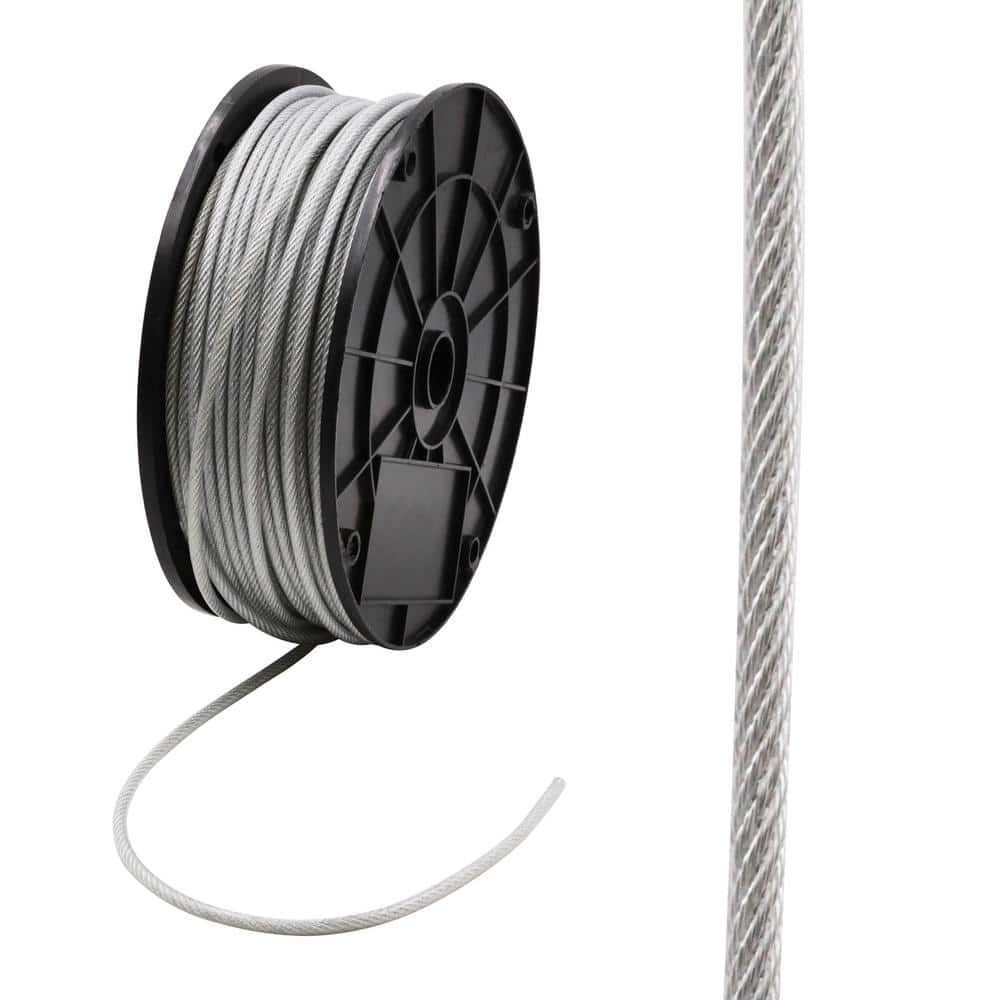
Stainless Steel Wire Rope1) Material: AISI304 AISI316 2) Construction: 7x37, 1x37, 7x19, 6x19+FE, 1x19, 7x7, 6x7+FE, 1x7. 3)Diameter 0.27mm - 30.00mm 4) Packing: on reels 5) Standard: DIN3055 ...
6x7 (6/1) - Fibre Core Wire Rope6x7 construction general purpose wire rope is available with either FC (fibre core) or WSC (wire strand core). When supplied with a WSC the rope is more commonly referr...
Coated Galvanised and Stainless Steel Wire Ropes We supply a full range of wire rope covered in a range of coatings including PVC, Polypropylene and Nylon as well as special coatings which we can cons...
Compacted Wire Rope Compacted Wire Rope has been subject to a compacting process suchas drawing rolling or swageing where by the metalic cross-sectional area of thewires remains unaltered whereas th...
Cable Inner Wire Thisis Inner Wire, available for Cars, Motorcycle, Tricycle, Bicycle. Etc. Wecan offer all kind of Inner wire. A:Φ8×10 Head 2.0mm Cable for MotorcycleB: Φ6×11 Head 1.5mm Cable for...
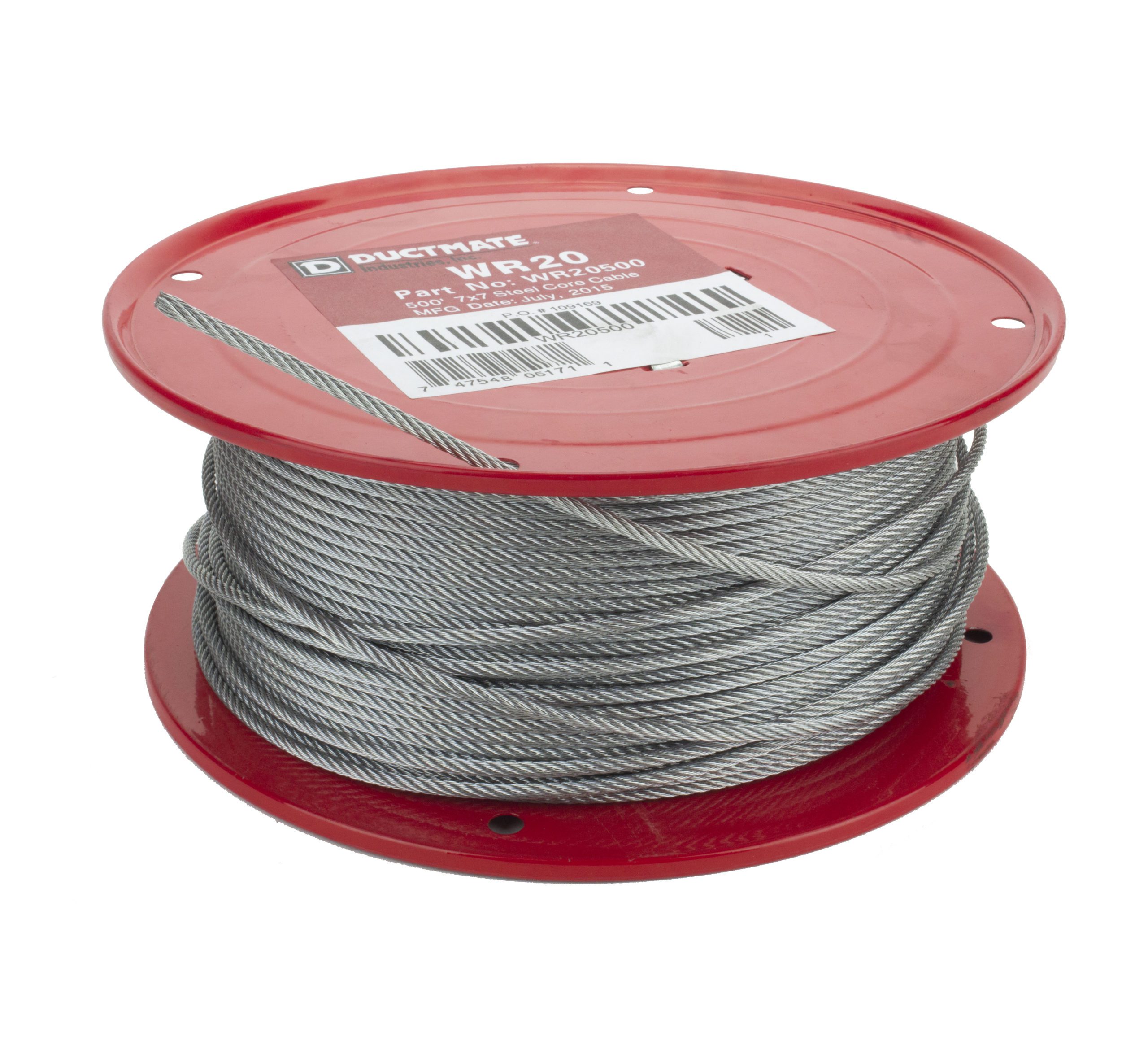
7x7 (6/1) - Wire Strand Core Wire Rope6x7 construction general purpose wire rope is available with either FC (fibre core) or WSC (wire strand core). When supplied with a WSC the rope is more commonly ...
1x19 - Marine Grade Stainless Steel Wire Rope 1x19 AISI316 (304) stainless steel strand is a very poplar stainless steel construction. Used heavily throughout the marine industry, 1x19’s ex...
6x19 (12/6/1) - Fibre Core Wire Rope6x19 construction wire rope is available with either FC (fibre core) or WSC (wire strand core). When supplied with a wsc the rope is more commonly referred to as 7x...
In stricter senses, the term wire rope refers to a diameter larger than 9.5 mm (3⁄8 in), with smaller gauges designated cable or cords.wrought iron wires were used, but today steel is the main material used for wire ropes.
Historically, wire rope evolved from wrought iron chains, which had a record of mechanical failure. While flaws in chain links or solid steel bars can lead to catastrophic failure, flaws in the wires making up a steel cable are less critical as the other wires easily take up the load. While friction between the individual wires and strands causes wear over the life of the rope, it also helps to compensate for minor failures in the short run.
Wire ropes were developed starting with mining hoist applications in the 1830s. Wire ropes are used dynamically for lifting and hoisting in cranes and elevators, and for transmission of mechanical power. Wire rope is also used to transmit force in mechanisms, such as a Bowden cable or the control surfaces of an airplane connected to levers and pedals in the cockpit. Only aircraft cables have WSC (wire strand core). Also, aircraft cables are available in smaller diameters than wire rope. For example, aircraft cables are available in 1.2 mm (3⁄64 in) diameter while most wire ropes begin at a 6.4 mm (1⁄4 in) diameter.suspension bridges or as guy wires to support towers. An aerial tramway relies on wire rope to support and move cargo overhead.
Modern wire rope was invented by the German mining engineer Wilhelm Albert in the years between 1831 and 1834 for use in mining in the Harz Mountains in Clausthal, Lower Saxony, Germany.chains, such as had been used before.
Wilhelm Albert"s first ropes consisted of three strands consisting of four wires each. In 1840, Scotsman Robert Stirling Newall improved the process further.John A. Roebling, starting in 1841suspension bridge building. Roebling introduced a number of innovations in the design, materials and manufacture of wire rope. Ever with an ear to technology developments in mining and railroading, Josiah White and Erskine Hazard, principal ownersLehigh Coal & Navigation Company (LC&N Co.) — as they had with the first blast furnaces in the Lehigh Valley — built a Wire Rope factory in Mauch Chunk,Pennsylvania in 1848, which provided lift cables for the Ashley Planes project, then the back track planes of the Summit Hill & Mauch Chunk Railroad, improving its attractiveness as a premier tourism destination, and vastly improving the throughput of the coal capacity since return of cars dropped from nearly four hours to less than 20 minutes. The decades were witness to a burgeoning increase in deep shaft mining in both Europe and North America as surface mineral deposits were exhausted and miners had to chase layers along inclined layers. The era was early in railroad development and steam engines lacked sufficient tractive effort to climb steep slopes, so incline plane railways were common. This pushed development of cable hoists rapidly in the United States as surface deposits in the Anthracite Coal Region north and south dove deeper every year, and even the rich deposits in the Panther Creek Valley required LC&N Co. to drive their first shafts into lower slopes beginning Lansford and its Schuylkill County twin-town Coaldale.
The German engineering firm of Adolf Bleichert & Co. was founded in 1874 and began to build bicable aerial tramways for mining in the Ruhr Valley. With important patents, and dozens of working systems in Europe, Bleichert dominated the global industry, later licensing its designs and manufacturing techniques to Trenton Iron Works, New Jersey, USA which built systems across America. Adolf Bleichert & Co. went on to build hundreds of aerial tramways around the world: from Alaska to Argentina, Australia and Spitsbergen. The Bleichert company also built hundreds of aerial tramways for both the Imperial German Army and the Wehrmacht.
In the last half of the 19th century, wire rope systems were used as a means of transmitting mechanical powercable cars. Wire rope systems cost one-tenth as much and had lower friction losses than line shafts. Because of these advantages, wire rope systems were used to transmit power for a distance of a few miles or kilometers.
Steel wires for wire ropes are normally made of non-alloy carbon steel with a carbon content of 0.4 to 0.95%. The very high strength of the rope wires enables wire ropes to support large tensile forces and to run over sheaves with relatively small diameters.
In the mostly used parallel lay strands, the lay length of all the wire layers is equal and the wires of any two superimposed layers are parallel, resulting in linear contact. The wire of the outer layer is supported by two wires of the inner layer. These wires are neighbors along the whole length of the strand. Parallel lay strands are made in one operation. The endurance of wire ropes with this kind of strand is always much greater than of those (seldom used) with cross lay strands. Parallel lay strands with two wire layers have the construction Filler, Seale or Warrington.
In principle, spiral ropes are round strands as they have an assembly of layers of wires laid helically over a centre with at least one layer of wires being laid in the opposite direction to that of the outer layer. Spiral ropes can be dimensioned in such a way that they are non-rotating which means that under tension the rope torque is nearly zero. The open spiral rope consists only of round wires. The half-locked coil rope and the full-locked coil rope always have a centre made of round wires. The locked coil ropes have one or more outer layers of profile wires. They have the advantage that their construction prevents the penetration of dirt and water to a greater extent and it also protects them from loss of lubricant. In addition, they have one further very important advantage as the ends of a broken outer wire cannot leave the rope if it has the proper dimensions.
Stranded ropes are an assembly of several strands laid helically in one or more layers around a core. This core can be one of three types. The first is a fiber core, made up of synthetic material or natural fibers like sisal. Synthetic fibers are stronger and more uniform but cannot absorb much lubricant. Natural fibers can absorb up to 15% of their weight in lubricant and so protect the inner wires much better from corrosion than synthetic fibers do. Fiber cores are the most flexible and elastic, but have the downside of getting crushed easily. The second type, wire strand core, is made up of one additional strand of wire, and is typically used for suspension. The third type is independent wire rope core (IWRC), which is the most durable in all types of environments.ordinary lay rope if the lay direction of the wires in the outer strands is in the opposite direction to the lay of the outer strands themselves. If both the wires in the outer strands and the outer strands themselves have the same lay direction, the rope is called a lang lay rope (from Dutch langslag contrary to kruisslag,Regular lay means the individual wires were wrapped around the centers in one direction and the strands were wrapped around the core in the opposite direction.
Multi-strand ropes are all more or less resistant to rotation and have at least two layers of strands laid helically around a centre. The direction of the outer strands is opposite to that of the underlying strand layers. Ropes with three strand layers can be nearly non-rotating. Ropes with two strand layers are mostly only low-rotating.
Stationary ropes, stay ropes (spiral ropes, mostly full-locked) have to carry tensile forces and are therefore mainly loaded by static and fluctuating tensile stresses. Ropes used for suspension are often called cables.
Track ropes (full locked ropes) have to act as rails for the rollers of cabins or other loads in aerial ropeways and cable cranes. In contrast to running ropes, track ropes do not take on the curvature of the rollers. Under the roller force, a so-called free bending radius of the rope occurs. This radius increases (and the bending stresses decrease) with the tensile force and decreases with the roller force.
Wire rope slings (stranded ropes) are used to harness various kinds of goods. These slings are stressed by the tensile forces but first of all by bending stresses when bent over the more or less sharp edges of the goods.
Technical regulations apply to the design of rope drives for cranes, elevators, rope ways and mining installations. Factors that are considered in design include:
Donandt force (yielding tensile force for a given bending diameter ratio D/d) - strict limit. The nominal rope tensile force S must be smaller than the Donandt force SD1.
The wire ropes are stressed by fluctuating forces, by wear, by corrosion and in seldom cases by extreme forces. The rope life is finite and the safety is only ensured by inspection for the detection of wire breaks on a reference rope length, of cross-section loss, as well as other failures so that the wire rope can be replaced before a dangerous situation occurs. Installations should be designed to facilitate the inspection of the wire ropes.
Lifting installations for passenger transportation require that a combination of several methods should be used to prevent a car from plunging downwards. Elevators must have redundant bearing ropes and a safety gear. Ropeways and mine hoistings must be permanently supervised by a responsible manager and the rope must be inspected by a magnetic method capable of detecting inner wire breaks.
The end of a wire rope tends to fray readily, and cannot be easily connected to plant and equipment. There are different ways of securing the ends of wire ropes to prevent fraying. The common and useful type of end fitting for a wire rope is to turn the end back to form a loop. The loose end is then fixed back on the wire rope. Termination efficiencies vary from about 70% for a Flemish eye alone; to nearly 90% for a Flemish eye and splice; to 100% for potted ends and swagings.
When the wire rope is terminated with a loop, there is a risk that it will bend too tightly, especially when the loop is connected to a device that concentrates the load on a relatively small area. A thimble can be installed inside the loop to preserve the natural shape of the loop, and protect the cable from pinching and abrading on the inside of the loop. The use of thimbles in loops is industry best practice. The thimble prevents the load from coming into direct contact with the wires.
A wire rope clip, sometimes called a clamp, is used to fix the loose end of the loop back to the wire rope. It usually consists of a U-bolt, a forged saddle, and two nuts. The two layers of wire rope are placed in the U-bolt. The saddle is then fitted to the bolt over the ropes (the saddle includes two holes to fit to the U-bolt). The nuts secure the arrangement in place. Two or more clips are usually used to terminate a wire rope depending on the diameter. As many as eight may be needed for a 2 in (50.8 mm) diameter rope.
The mnemonic "never saddle a dead horse" means that when installing clips, the saddle portion of the assembly is placed on the load-bearing or "live" side, not on the non-load-bearing or "dead" side of the cable. This is to protect the live or stress-bearing end of the rope against crushing and abuse. The flat bearing seat and extended prongs of the body are designed to protect the rope and are always placed against the live end.
An eye splice may be used to terminate the loose end of a wire rope when forming a loop. The strands of the end of a wire rope are unwound a certain distance, then bent around so that the end of the unwrapped length forms an eye. The unwrapped strands are then plaited back into the wire rope, forming the loop, or an eye, called an eye splice.
A Flemish eye, or Dutch Splice, involves unwrapping three strands (the strands need to be next to each other, not alternates) of the wire and keeping them off to one side. The remaining strands are bent around, until the end of the wire meets the "V" where the unwrapping finished, to form the eye. The strands kept to one side are now re-wrapped by wrapping from the end of the wire back to the "V" of the eye. These strands are effectively rewrapped along the wire in the opposite direction to their original lay. When this type of rope splice is used specifically on wire rope, it is called a "Molly Hogan", and, by some, a "Dutch" eye instead of a "Flemish" eye.
Swaging is a method of wire rope termination that refers to the installation technique. The purpose of swaging wire rope fittings is to connect two wire rope ends together, or to otherwise terminate one end of wire rope to something else. A mechanical or hydraulic swager is used to compress and deform the fitting, creating a permanent connection. Threaded studs, ferrules, sockets, and sleeves are examples of different swaged terminations.
A wedge socket termination is useful when the fitting needs to be replaced frequently. For example, if the end of a wire rope is in a high-wear region, the rope may be periodically trimmed, requiring the termination hardware to be removed and reapplied. An example of this is on the ends of the drag ropes on a dragline. The end loop of the wire rope enters a tapered opening in the socket, wrapped around a separate component called the wedge. The arrangement is knocked in place, and load gradually eased onto the rope. As the load increases on the wire rope, the wedge become more secure, gripping the rope tighter.
Poured sockets are used to make a high strength, permanent termination; they are created by inserting the wire rope into the narrow end of a conical cavity which is oriented in-line with the intended direction of strain. The individual wires are splayed out inside the cone or "capel", and the cone is then filled with molten lead-antimony-tin (Pb80Sb15Sn5) solder or "white metal capping",zincpolyester resin compound.
Donald Sayenga. "Modern History of Wire Rope". History of the Atlantic Cable & Submarine Telegraphy (atlantic-cable.com). Archived from the original on 3 February 2014. Retrieved 9 April 2014.
Prices shown are list prices and include all electrical controls per applicable N.E.C. Specifications. NEMA enclosure with quick disconnect plugs, hoist completely wired and reeved. All prices are for 460/3/60 power. Adders for 208/3/60 or 230/3/60 are shown on options page. Push button station and 110V control transformer are optional.
A wire sawing steel also known as concrete wire saw is used for particularly challenging projects where traditional saws would not work. They are used because of their versatility and effectiveness in wire sawing concrete. Wire sawing steel are mainly used to cut through concrete structures, cross-sections, and other complex objects which manual saws are often unable to do effectively. Once set up, wire saw through any concrete, stone, or metal structure.
Some wire saws like the concrete wire saw are embedded with diamond segments on the thin steel wire to cut through hard materials via abrasions. The wire is threaded across a system of pulleys that are aligned within the direction of the cut. To keep the wire moisturized, and the system from overheating from extreme friction, water is fed across the system.
A basic wire saw consists of a wire rope that has two rings attached to each of its four corners. The wire rope can consist of a single strand or a number of strands that are braided together. Recently, the saw-wire body of the wire rope has been adorned with a sizeable quantity of abrasive granules that have been firmly fastened. In its most basic form, it is made up of saw wire rope in addition to a significant number of abrasive grains that have been firmly fastened on the outside surface of the coil by metal.
Cutting is the primary function of the most basic sort of wire sawing steel, which consists of little more than a metal wire or cable. It is typically classified as survivalist gear and may be obtained at stores that specialise in climbing and hunting. It is typically used for chopping branches. In recent years, wire saws have been used to cut a wide variety of materials, including ceramics, wood, rock, silicon carbide, sapphire, lithium niobate, sapphire, sapphire, foam ceramics, and sapphire. Wire saws of the continuous type are used for significant building projects and cutting. Additionally, they were utilised in the industry of photovoltaics and semiconductors for the purpose of cutting silicon wafers. Diamond wire saws are utilised for the cutting of various metal components. In addition, laboratories frequently employ wire saws for cutting crystals and other materials. In addition, oscillating as well as continuous types of wire saws are utilised for the process of cutting shapes out of stained glass.
When it comes to wire sawing steel, the wire saw has several qualities, one of which is the precision of the cut that it offers. As a result of the fact that they may cut in any direction, they can be utilised for the purpose of cutting elaborate shapes in stained glass. Due to the fact that it has a narrower kerf, it is an invaluable instrument for use when cutting expensive materials or while performing other tasks that need precise cuts.
If the job requires areas of concrete to be completely removed, situations where space is limited, a difficult construction project that involves cutting through steel-incased concrete, concrete-encased steel support, concrete retaining walls, reinforced bar, or underwater where navigating bulky equipment is difficult, that is when you know you need wire sawing steel and wire cutting services.
Since water is used to lubricate and prevent the system from overheating, you would expect much lesser dusts from wire sawing steel, keeping the workers safe and very easy to clean after.
The wire is guided through pre-cut drill holes, so cuts are precise to the shape and sized specified. And since they are narrower and thinner compared to others, the cuts can be completed with more precision.
Since wire sawing steel require minimal space to operate and are not manually operated, they are more flexible to use in jobs with hard-to-reach places and are in challenging environments like underwater.
Wire sawing steel cause minimal vibrations which in result cases much less noise than other concrete cutting methods and construction equipment. This method is ideal in housing environments, workplaces, or night operations.
Since manual labor is not needed in wire sawing concrete wall and is all motor operated, the machine can cut at a consistent speed without breaks getting the job completed much quicker and on schedule.
It uses abrasion instead of saw teeth for cutting that is why a wire sawing steel is an effective tool when it comes to cutting. Wire sawing metal offers significant advantages over other cutting methods in various applications compared to other cutting methods. High precision can reduce damage of wire sawing, and reduced kerf loss are some of the areas in which a wire saw thought to be an effective tool.
It is for the reason that it can have a preeminent effect not only on the process of cutting but also on downstream operations. There is less damage depth on the surface of the cut because wire sawing steel is a gentle process. The reduced damage and gentle cutting men the corners also cut cleanly, and quality is improved. It is an excellent solution to many challenges that companies face when that look towards other thin pieces of valuable and delicate materials.
Although wire sawing steel is remotely operated it does not mean chances of injury is 0. Since they are under extreme tension, there is a possibility that they can snap and cause serious injury to anyone nearby. Always take proper safety precautions when using it. And as always, only let trained specialists should operate them.
There is a wide range of applications for wire sawing steel. Mining and quarrying industries are one of the main industries that use them to cut hard stones into large blocks. Some wire saw uses diamond impregnated beads (Diamond wire sawing technology). Some use abrasive wire saw, either automatic or manual and is commonly used for cutting the different shapes and sizes. Some industry like the furniture industry uses them to cut cushions and couches, etc. In the housing industry, they are also used for insulation and pipe insulation.
Unfortunately, the cost of wire sawing steel is greater than the cost of using more conventional sawing methods. This should not come as much of a surprise given that a high-quality product that is interlaced with diamond beads and has the power to cut through big concrete structures will never be sold at a low price.
Wire sawing steel, on the other hand, is more expensive than other methods since the wires used in the process are typically not made to last, or at least are not expected to last. After roughly six cuts, the wires either snap or get worn out to the point where they no longer operate properly, rendering the diamond grit unusable.
Because it takes a significant amount of time to repair the wires when they break, a cut that would have been anticipated to take no time at all suddenly takes far longer than anticipated. The management of projects may have significant difficulties as a result of this.
In addition, if your wire cutters break, you could put yourself in danger because a wire that breaks while it is under stress can cause whiplash. However, this can be countered by taking the necessary procedures to protect one’s health and safety.
Band saws are saws that have a lengthy, sharp edge with a continuous band of grooved metal that extends between two or more wheels to cut material. These saws can cut through a multitude of materials, including wood, plastic, and metal. It is possible to cut thicker chunks of glass or any other material with this tool. There are certain key distinctions that can be made between a band saw and a wire saw, despite the fact that both are utilised for cutting. A slab with a maximum height of three inches can be cut using the band saw. On the other hand, wire sawing steel has a cutting capacity of no more than around 3/8 inch. In addition to this, the operator of a wire saw has the ability to cut in any direction, which may be necessary in some circumstances, whereas the operator of a band saw would need to make a lead-in cut in order to cut such a pattern. Thirdly, the wire that is used in wire sawing steel is thicker than the blade that is used in a band saw; as a result, the wire saw is able to remove more material with each cut than a band saw.
Due to friction and heat, they might get overheated or break, while any surface imperfections can defect the cuts. It is not a simple equipment thus needs to be taken care of very well. They are often lubricated and cooled by oil or water. To prevent rusting, it is important to daub grease on it. Also, it would be best if you clean the dirt on the wire saw quickly after using and also before using it to prevent dirt corrosion or equipment and prevent it from damage.
Dubbed to be one of the best wire cutting company, it is on top in terms of wire cutting machine companies also. With years of experienced, manned with highly skilled employees, top-of-the-line equipment and machineries, and advance modern approach, you are surely getting grade A quality service that you would not find anywhere. If you have questions you can explore our official website or contact us so we can directly answer your questions.

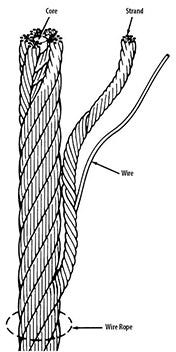
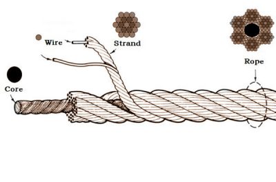
Wire rope and cable are each considered a “machine”. The configuration and method of manufacture combined with the proper selection of material when designed for a specific purpose enables a wire rope or cable to transmit forces, motion and energy in some predetermined manner and to some desired end.
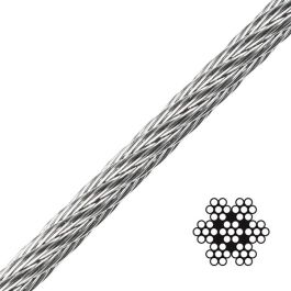
Two or more wires concentrically laid around a center wire is called a strand. It may consist of one or more layers. Typically, the number of wires in a strand is 7, 19 or 37. A group of strands laid around a core would be called a cable or wire rope. In terms of product designation, 7 strands with 19 wires in each strand would be a 7×19 cable: 7 strands with 7 wires in each strand would be a 7×7 cable.
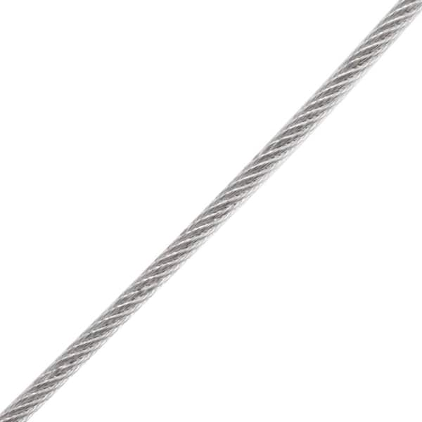
Materials Different applications for wire rope present varying demands for strength, abrasion and corrosion resistance. In order to meet these requirements, wire rope is produced in a number of different materials.
Stainless Steel This is used where corrosion is a prime factor and the cost increase warrants its use. The 18% chromium, 8% nickel alloy known as type 302 is the most common grade accepted due to both corrosion resistance and high strength. Other types frequently used in wire rope are 304, 305, 316 and 321, each having its specific advantage over the other. Type 305 is used where non-magnetic properties are required, however, there is a slight loss of strength.
Galvanized Carbon Steel This is used where strength is a prime factor and corrosion resistance is not great enough to require the use of stainless steel. The lower cost is usually a consideration in the selection of galvanized carbon steel. Wires used in these wire ropes are individually coated with a layer of zinc which offers a good measure of protection from corrosive elements.
Cable Construction The greater the number of wires in a strand or cable of a given diameter, the more flexibility it has. A 1×7 or a 1×19 strand, having 7 and 19 wires respectively, is used principally as a fixed member, as a straight linkage, or where flexing is minimal.
Selecting Wire Rope When selecting a wire rope to give the best service, there are four requirements which should be given consideration. A proper choice is made by correctly estimating the relative importance of these requirements and selecting a rope which has the qualities best suited to withstand the effects of continued use. The rope should possess:Strength sufficient to take care of the maximum load that may be applied, with a proper safety factor.
Strength Wire rope in service is subjected to several kinds of stresses. The stresses most frequently encountered are direct tension, stress due to acceleration, stress due to sudden or shock loads, stress due to bending, and stress resulting from several forces acting at one time. For the most part, these stresses can be converted into terms of simple tension, and a rope of approximately the correct strength can be chosen. As the strength of a wire rope is determined by its, size, grade and construction, these three factors should be considered.
Safety Factors The safety factor is the ratio of the strength of the rope to the working load. A wire rope with a strength of 10,000 pounds and a total working load of 2,000 pounds would be operating with a safety factor of five.
It is not possible to set safety factors for the various types of wire rope using equipment, as this factor can vary with conditions on individual units of equipment.
The proper safety factor depends not only on the loads applied, but also on the speed of operation, shock load applied, the type of fittings used for securing the rope ends, the acceleration and deceleration, the length of rope, the number, size and location of sheaves and drums, the factors causing abrasion and corrosion and the facilities for inspection.
Fatigue Fatigue failure of the wires in a wire rope is the result of the propagation of small cracks under repeated applications of bending loads. It occurs when ropes operate over comparatively small sheaves or drums. The repeated bending of the individual wires, as the rope bends when passing over the sheaves or drums, and the straightening of the individual wires, as the rope leaves the sheaves or drums, causing fatigue. The effect of fatigue on wires is illustrated by bending a wire repeatedly back and forth until it breaks.
The best means of preventing early fatigue of wire ropes is to use sheaves and drums of adequate size. To increase the resistance to fatigue, a rope of more flexible construction should be used, as increased flexibility is secured through the use of smaller wires.
Abrasive Wear The ability of a wire rope to withstand abrasion is determined by the size, the carbon and manganese content, the heat treatment of the outer wires and the construction of the rope. The larger outer wires of the less flexible constructions are better able to withstand abrasion than the finer outer wires of the more flexible ropes. The higher carbon and manganese content and the heat treatment used in producing wire for the stronger ropes, make the higher grade ropes better able to withstand abrasive wear than the lower grade ropes.
Effects of Bending All wire ropes, except stationary ropes used as guys or supports, are subjected to bending around sheaves or drums. The service obtained from wire ropes is, to a large extent, dependent upon the proper choice and location of the sheaves and drums about which it operates.
A wire rope may be considered a machine in which the individual elements (wires and strands) slide upon each other when the rope is bent. Therefore, as a prerequisite to the satisfactory operation of wire rope over sheaves and drums, the rope must be properly lubricated.
Loss of strength due to bending is caused by the inability of the individual strands and wires to adjust themselves to their changed position when the rope is bent. Tests made by the National Institute of Standards and Technology show that the rope strength decreases in a marked degree as the sheave diameter grows smaller with respect to the diameter of the rope. The loss of strength due to bending wire ropes over the sheaves found in common use will not exceed 6% and will usually be about 4%.
The bending of a wire rope is accompanied by readjustment in the positions of the strands and wires and results in actual bending of the wires. Repetitive flexing of the wires develops bending loads which, even though well within the elastic limit of the wires, set up points of stress concentration.
The fatigue effect of bending appears in the form of small cracks in the wires at these over-stressed foci. These cracks propagate under repeated stress cycles, until the remaining sound metal is inadequate to withstand the bending load. This results in broken wires showing no apparent contraction of cross section.
Experience has established the fact that from the service view-point, a very definite relationship exists between the size of the individual outer wires of a wire rope and the size of the sheave or drum about which it operates. Sheaves and drums smaller than 200 times the diameter of the outer wires will cause permanent set in a heavily loaded rope. Good practice requires the use of sheaves and drums with diameters 800 times the diameter of the outer wires in the rope for heavily loaded fast-moving ropes.
It is impossible to give a definite minimum size of sheave or drum about which a wire rope will operate with satisfactory results, because of the other factors affecting the useful life of the rope. If the loads are light or the speed slow, smaller sheaves and drums can be used without causing early fatigue of the wires than if the loads are heavy or the speed is fast. Reverse bends, where a rope is bent in one direction and then in the opposite direction, cause excessive fatigue and should be avoided whenever possible. When a reverse bend is necessary larger sheaves are required than would be the case if the rope were bent in one direction only.
Stretch of Wire Rope The stretch of a wire rope under load is the result of two components: the structural stretch and the elastic stretch. Structural stretch of wire rope is caused by the lengthening of the rope lay, compression of the core and adjustment of the wires and strands to the load placed upon the wire rope. The elastic stretch is caused by elongation of the wires.
The structural stretch varies with the size of core, the lengths of lays and the construction of the rope. This stretch also varies with the loads imposed and the amount of bending to which the rope is subjected. For estimating this stretch the value of one-half percent, or .005 times the length of the rope under load, gives an approximate figure. If loads are light, one-quarter percent or .0025 times the rope length may be used. With heavy loads, this stretch may approach one percent, or .01 times the rope length.
The elastic stretch of a wire rope is directly proportional to the load and the length of rope under load, and inversely proportional to the metallic area and modulus of elasticity. This applies only to loads that do not exceed the elastic limit of a wire rope. The elastic limit of stainless steel wire rope is approximately 60% of its breaking strength and for galvanized ropes it is approximately 50%.
Preformed Wire Ropes Preformed ropes differ from the standard, or non-preformed ropes, in that the individual wires in the strands and the strands in the rope are preformed, or pre-shaped to their proper shape before they are assembled in the finished rope.
This, in turn, results in preformed wire ropes having the following characteristics:They can be cut without the seizings necessary to retain the rope structure of non-preformed ropes.
They are substantially free from liveliness and twisting tendencies. This makes installation and handling easier, and lessens the likelihood of damage to the rope from kinking or fouling. Preforming permits the more general use of Lang lay and wire core constructions.
Removal of internal stresses increase resistance to fatigue from bending. This results in increased service where ability to withstand bending is the important requirement. It also permits the use of ropes with larger outer wires, when increased wear resistance is desired.
Outer wires will wear thinner before breaking, and broken wire ends will not protrude from the rope to injure worker’s hands, to nick and distort adjacent wires, or to wear sheaves and drums. Because of the fact that broken wire ends do not porcupine, they are not as noticeable as they are in non-preformed ropes. This necessitates the use of greater care when inspecting worn preformed ropes, to determine their true condition.
Wire rope slings, or cable slings, have always been the standard choice for heavy-duty operations, owing to their strength, abrasion resistance, resilience, and flexibility. To top that, they can also lift hot objects with ease.
Generally, these lifting slings are made of multiple wire strands twisted around a steel or fiber core. The material of the wire, coupled with the core and strand structure, determines the end-application of the sling.
The structure of the wire sling makes it difficult to inspect. This is dangerous since a single damaged link can jeopardize your lifting operation, putting the load and the crew in harm’s way.
Damaged cable slings cannot be repaired. The Occupational Safety and Health Administration(OSHA ) advises users to immediately discard slings with broken wires, severe locational bruising, evidence of heat damage, and missing identifications, among other things.
Synthetic slings are more prone to cuts and abrasions than wire ropes or chains. Also, they do not respond well to chemicals and UV rays. Each of these factors can significantly reduce its capacity to carry heavy loads.
The load’s center of gravity.Unless the object is properly centered, it may swing off-balance and crash into people or property nearby. For oddly-shaped objects, you can use synthetic slings to play it safe.

The 6×7 steel wire rope available with IWRC (independent wire rope core) or FB (fibre core). Popular from 0.5mm. to 2mm. diameter. The 6×7 steel wire rope with diameter beyond 6mm. will becomes stiff. Suitable for use when the wire rope is not constant in motion.


 8613371530291