
wire rope 3d model price
Wire ropes are used dynamically for lifting and hoisting in cranes and elevators, and for transmission of mechanical power. ...Wire rope is also used to transmit force in mechanisms. ...The rope is designed in Solidworks 2020
Two sizes for wire rope. One is 1/8in and the other is 1/4in. The three holes in the middle are for attaching it to a drive rod from a servo motor to lift things up. ...I used 3mm metal rods to attach it to the drive rod.

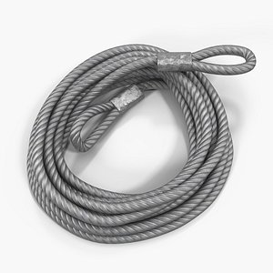
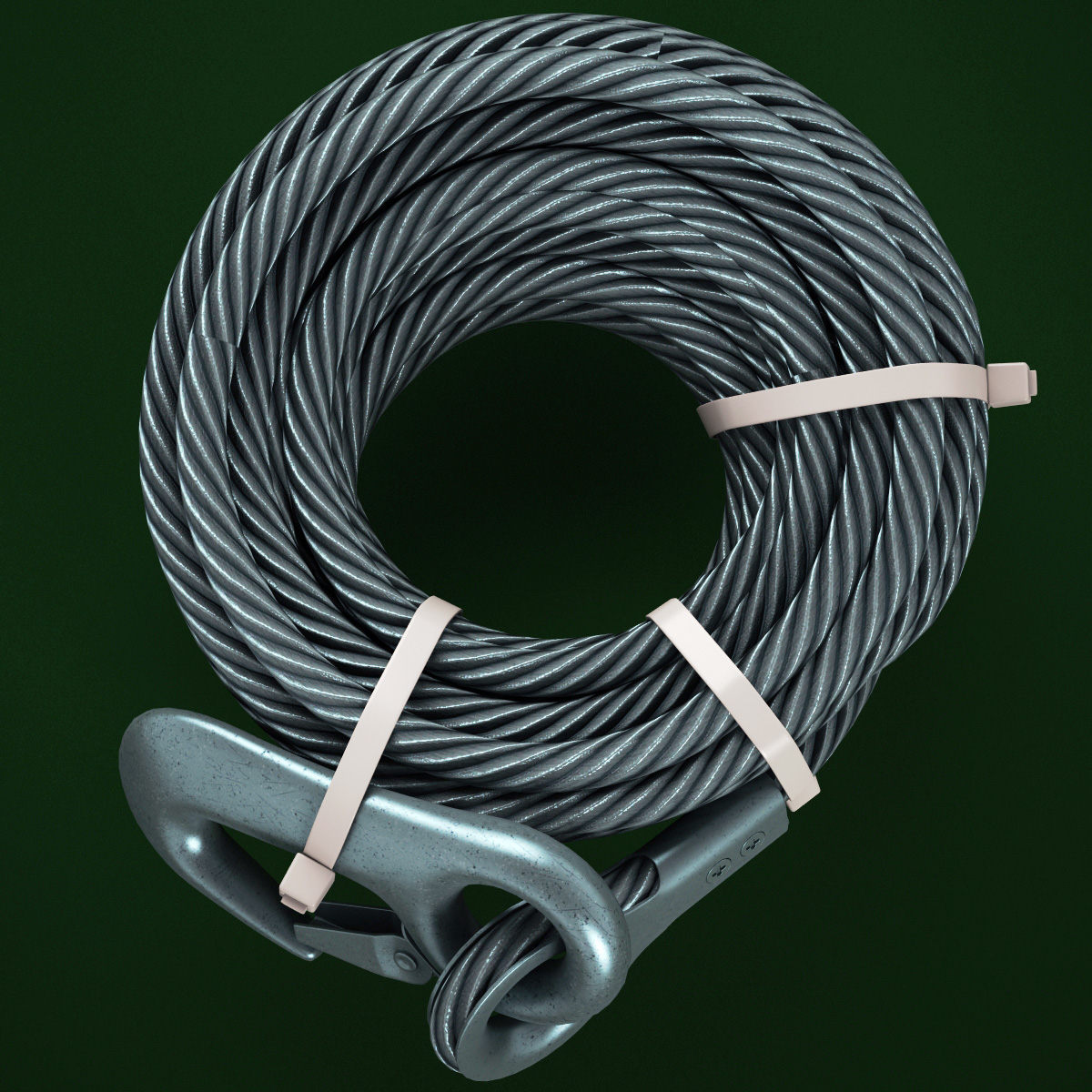
Steel Wire Rope is a high quality model to add more details and realism to your projects. Detailed enough for close-up renders. Comes with detailed textures(4096x4096).

Wire rope consists of several strands of metal wire laid (twisted) into a helix. The term "cable" is often used interchangeably with "wire rope", but narrower senses exist in which "wire rope" refers to diameter larger than 3/8 inch (9.52 mm), whereas sizes smaller than this are designated cable or cords.wrought iron wires were used, but today steel is the main material used for wire ropes.
Historically wire rope evolved from wrought iron chains, which had a record of mechanical failure. While flaws in chain links or solid steel bars can lead to catastrophic failure, flaws in the wires making up a steel cable are less critical as the other wires easily take up the load. Friction between the individual wires and strands, as a consequence of their twist, further compensates for any flaws.
Wire ropes were developed starting with mining hoist applications in the 1830s. Wire ropes are used dynamically for lifting and hoisting in cranes and elevators, and for transmission of mechanical power. Wire rope is also used to transmit force in mechanisms, such as a Bowden cable or the control surfaces of an airplane connected to levers and pedals in the cockpit. Only aircraft cables have WSC (wire strand core). Also, aircraft cables are available in smaller diameters than wire rope. For example, aircraft cables are available in 3/64 in. diameter while most wire ropes begin at a 1/4 in. diameter.suspension bridges or as guy wires to support towers. An aerial tramway relies on wire rope to support and move cargo overhead.
Modern wire rope was invented by the German mining engineer Wilhelm Albert in the years between 1831 and 1834 for use in mining in the Harz Mountains in Clausthal, Lower Saxony, Germany.chains, such as had been used before.
Wilhelm Albert"s first ropes consisted of three strands consisting of four wires each. In 1840, Scotsman Robert Stirling Newall improved the process further.John A. Roebling, starting in 1841 suspension bridge building. Roebling introduced a number of innovations in the design, materials and manufacture of wire rope. Ever with an ear to technology developments in mining and railroading, Josiah White and Erskine Hazard, principal ownersLehigh Coal & Navigation Company (LC&N Co.) — as they had with the first blast furnaces in the Lehigh Valley — built a Wire Rope factory in Mauch Chunk,Pennsylvania in 1848, which provided lift cables for the Ashley Planes project, then the back track planes of the Summit Hill & Mauch Chunk Railroad, improving its attractiveness as a premier tourism destination, and vastly improving the throughput of the coal capacity since return of cars dropped from nearly four hours to less than 20 minutes. The decades were witness to a burgeoning increase in deep shaft mining in both Europe and North America as surface mineral deposits were exhausted and miner had to chase layers along inclined layers. The era was early in railroad development and steam engines having sufficient tractive effort to climb steep slopes were in the future, so incline plane railways were common, and the mining tunnels along inclined shafts between coal layers were just a which came first variant, but where steam engines could not go. This pushed development of cable hoists rapidly in the United States as surface deposits in the Anthracite Coal Region north and south dove deeper every year, and even the rich deposits in the Panther Creek Valley required LC&N Co. to drive their first shafts into lower slopes beginning Lansford and its Schuylkill County twin-town Coaldale.
The German engineering firm of Adolf Bleichert & Co. was founded in 1874 and began to build bicable aerial tramways for mining in the Ruhr Valley. With important patents, and dozens of working systems in Europe, Bleichert dominated the global industry, later licensing its designs and manufacturing techniques to Trenton Iron Works, New Jersey, USA which built systems across America. Adolf Bleichert & Co. went on to build hundreds of aerial tramways around the world: from Alaska to Argentina, Australia and Spitsbergen. The Bleichert company also built hundreds of aerial tramways for both the Imperial German Army and the Wehrmacht.
In the last half of the 19th century, wire rope systems were used as a means of transmitting mechanical powercable cars. Wire rope systems cost one-tenth as much and had lower friction losses than line shafts. Because of these advantages, wire rope systems were used to transmit power for a distance of a few miles or kilometers.
Steel wires for wire ropes are normally made of non-alloy carbon steel with a carbon content of 0.4 to 0.95%. The very high strength of the rope wires enables wire ropes to support large tensile forces and to run over sheaves with relatively small diameters.
In the mostly used parallel lay strands, the lay length of all the wire layers is equal and the wires of any two superimposed layers are parallel, resulting in linear contact. The wire of the outer layer is supported by two wires of the inner layer. These wires are neighbours along the whole length of the strand. Parallel lay strands are made in one operation. The endurance of wire ropes with this kind of strand is always much greater than of those (seldom used) with cross lay strands. Parallel lay strands with two wire layers have the construction Filler, Seale or Warrington.
In principle, spiral ropes are round strands as they have an assembly of layers of wires laid helically over a centre with at least one layer of wires being laid in the opposite direction to that of the outer layer. Spiral ropes can be dimensioned in such a way that they are non-rotating which means that under tension the rope torque is nearly zero.
The open spiral rope consists only of round wires. The half-locked coil rope and the full-locked coil rope always have a centre made of round wires. The locked coil ropes have one or more outer layers of profile wires. They have the advantage that their construction prevents the penetration of dirt and water to a greater extent and it also protects them from loss of lubricant. In addition, they have one further very important advantage as the ends of a broken outer wire cannot leave the rope if it has the proper dimensions.
Stranded ropes are an assembly of several strands laid helically in one or more layers around a core. This core can be one of three types. The first is a fiber core, made up of synthetic material or natural fibers like Sysal. Synthetic fibers are stronger and more uniform but can"t absorb much lubricant. Natural fibers can absorb up to 15% of their weight in lubricant and so protect the inner wires much better from corrosion than synthetic fibers do. Fiber cores are the most flexible and elastic, but have the downside of getting crushed easily. The second type, wire strand core, is made up of one additional strand of wire, and is typically used for suspension. The third type is independent wire rope core (IWRC), which is the most durable in all types of environments.ordinary lay rope if the lay direction of the wires in the outer strands is in the opposite direction to the lay of the outer strands themselves. If both the wires in the outer strands and the outer strands themselves have the same lay direction, the rope is called a lang lay rope (formerly Albert’s lay or Lang’s lay). Regular lay means the individual wires were wrapped around the centers in one direction and the strands were wrapped around the core in the opposite direction.
Multi-strand ropes are all more or less resistant to rotation and have at least two layers of strands laid helically around a centre. The direction of the outer strands is opposite to that of the underlying strand layers. Ropes with three strand layers can be nearly non-rotating. Ropes with two strand layers are mostly only low-rotating.
Stationary ropes, stay ropes (spiral ropes, mostly full-locked) have to carry tensile forces and are therefore mainly loaded by static and fluctuating tensile stresses. Ropes used for suspension are often called cables.
Track ropes (full locked ropes) have to act as rails for the rollers of cabins or other loads in aerial ropeways and cable cranes. In contrast to running ropes, track ropes do not take on the curvature of the rollers. Under the roller force, a so-called free bending radius of the rope occurs. This radius increases (and the bending stresses decrease) with the tensile force and decreases with the roller force.
Wire rope slings (stranded ropes) are used to harness various kinds of goods. These slings are stressed by the tensile forces but first of all by bending stresses when bent over the more or less sharp edges of the goods.
There are technical regulations for the rope drives of cranes, elevators, rope ways and mining installations not exceeding a given tensile force and not falling short of a given diameter ratio D/d of sheave and rope diameters. A general dimensioning method of rope drives (and used besides the technical regulations) calculate the five limits
Donandt force (yielding tensile force for a given bending diameter ratio D/d) - strict limit. The nominal rope tensile force S must be smaller than the Donandt force SD1.
Rope safety factor = minimum breaking force Fmin / nominal rope tensile force S. (ability to resist extreme impact forces) - Fmin/S ≥ 2,5 for simple lifting appliance
Discarding number of wire breaks (detection to need rope replacement) Minimum number of wire breaks on a reference rope length of 30d should be BA30 ≥ 8 for lifting appliance
Optimal rope diameter with the max. rope endurance for a given sheave diameter D and tensile rope force S - For economic reasons the rope diameter should be near to but smaller than the optimal rope diameter d ≤ dopt.
The wire ropes are stressed by fluctuating forces, by wear, by corrosion and in seldom cases by extreme forces. The rope life is finite and the safety is only ensured by inspection for the detection of wire breaks on a reference rope length, of cross-section loss, as well as other failures so that the wire rope can be replaced before a dangerous situation occurs. Installations should be designed to facilitate the inspection of the wire ropes.
Lifting installations for passenger transportation require that a combination of several methods should be used to prevent a car from plunging downwards. Elevators must have redundant bearing ropes and a safety gear. Ropeways and mine hoistings must be permanently supervised by a responsible manager and the rope must be inspected by a magnetic method capable of detecting inner wire breaks.
The end of a wire rope tends to fray readily, and cannot be easily connected to plant and equipment. There are different ways of securing the ends of wire ropes to prevent fraying. The most common and useful type of end fitting for a wire rope is to turn the end back to form a loop. The loose end is then fixed back on the wire rope. Termination efficiencies vary from about 70% for a Flemish eye alone; to nearly 90% for a Flemish eye and splice; to 100% for potted ends and swagings.
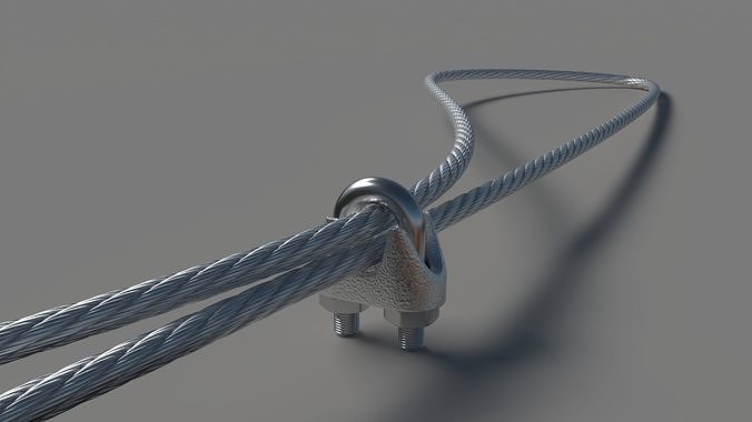
When the wire rope is terminated with a loop, there is a risk that it will bend too tightly, especially when the loop is connected to a device that concentrates the load on a relatively small area. A thimble can be installed inside the loop to preserve the natural shape of the loop, and protect the cable from pinching and abrading on the inside of the loop. The use of thimbles in loops is industry best practice. The thimble prevents the load from coming into direct contact with the wires.
A wire rope clamp, also called a clip, is used to fix the loose end of the loop back to the wire rope. It usually consists of a U-shaped bolt, a forged saddle, and two nuts. The two layers of wire rope are placed in the U-bolt. The saddle is then fitted over the ropes on to the bolt (the saddle includes two holes to fit to the u-bolt). The nuts secure the arrangement in place. Three or more clamps are usually used to terminate a wire rope. As many as eight may be needed for a 2 in (50.8 mm) diameter rope.
There is an old adage; be sure not to "saddle a dead horse." This means that when installing clamps, the saddle portion of the clamp assembly is placed on the load-bearing or "live" side, not on the non-load-bearing or "dead" side of the cable. According to the US Navy Manual S9086-UU-STM-010, Chapter 613R3, Wire and Fiber rope and Rigging, "This is to protect the live or stress-bearing end of the rope against crushing and abuse. The flat bearing seat and extended prongs of the body (saddle) are designed to protect the rope and are always placed against the live end."
An eye splice may be used to terminate the loose end of a wire rope when forming a loop. The strands of the end of a wire rope are unwound a certain distance, and plaited back into the wire rope, forming the loop, or an eye, called an eye splice. When this type of rope splice is used specifically on wire rope, it is called a "Molly Hogan", and, by some, a "Dutch" eye instead of a "Flemish" eye.
Swaging is a method of wire rope termination that refers to the installation technique. The purpose of swaging wire rope fittings is to connect two wire rope ends together, or to otherwise terminate one end of wire rope to something else. A mechanical or hydraulic swager is used to compress and deform the fitting, creating a permanent connection. There are many types of swaged fittings. Threaded Studs, Ferrules, Sockets, and Sleeves are a few examples.
A wedge socket termination is useful when the fitting needs to be replaced frequently. For example, if the end of a wire rope is in a high-wear region, the rope may be periodically trimmed, requiring the termination hardware to be removed and reapplied. An example of this is on the ends of the drag ropes on a dragline. The end loop of the wire rope enters a tapered opening in the socket, wrapped around a separate component called the wedge. The arrangement is knocked in place, and load gradually eased onto the rope. As the load increases on the wire rope, the wedge become more secure, gripping the rope tighter.
Poured sockets are used to make a high strength, permanent termination; they are created by inserting the wire rope into the narrow end of a conical cavity which is oriented in-line with the intended direction of strain. The individual wires are splayed out inside the cone or "capel", and the cone is then filled with molten lead-antimony-tin (Pb80Sb15Sn5) solder or "white metal capping",zincpolyester resin compound.
Due to the rapid development of 3d technology, printed silk production and sales has become the focus of the industry. In order to meet the needs of customers and factories, our company research and design the 3 d print wire production line.
Wire ropes are in widespread use as structural members. A wire rope mostly consists of strands helically twisted around the central core. The strand is constituted of many wires helically wrapped around the inner wire. This implies that the rope geometry can be complicated [1]. Wire ropes are generally used to transmit tensile forces. They have high load-bearing capacities upon relatively small dead weights [2]. Moreover, the rope structure enables the wire ropes to resume loads despite the break of one or more wires [1]. Wire ropes are commonly used in civil and mechanical engineering, e.g., in bridges, cranes, cable cars, mine hoists, elevators, prestressed concrete structures, road safety equipment, and other similar applications [3,4,5,6,7].
Due to the increasing usages of ropes, numerous works investigating their performance have been published. They present, among other aspects, experimental tests [8], numerical tests [9,10], fatigue analysis [11], performances in various environments and conditions, and the behavior of partly damaged [1] or corroded wire ropes [5]. Developing a mathematical model for predicting wire rope responses is challenging due to the complex architecture of ropes, particularly if the effect of contact and frictional forces between wires is to be considered [12]. Most mathematical models are limited to a single, straight strand, where all wound wires are single helices [3,13,14]. However, most actual ropes consist of several or more strands in which most wires are configured as double helices [3,15]. To analyze ropes with a complex topology and to include various factors in calculations, the Finite Element Method (FEM) is increasingly being employed [16,17].
One analytical model was proposed by Costello (1997) [13]. It describes the equilibrium of a single wire, as well as static responses of a single strand and wire rope. Argatov (2011) [3] studied the response of a wire rope strand to axial and torsional loads. The refined discrete mathematical model was developed to correctly assess its deformation, taking into account interwire contacts. This model enables local contact stresses to be obtained. Argatov et al. (2011) [4] studied the wear degradation of wire ropes subjected to cyclic bending over a sheave by applying the Archard–Kragelsky wear law. The proposed mathematical model can be useful for estimating the fatigue life of wire ropes.
Nowadays, numerous research employing numerical simulations is being conducted. FEM simulations make it possible to analyze the response of wire ropes in detail, even for a complicated geometry. The most valuable simulations are those compared and validated against experiments. Generally, numerical models of wire ropes can be divided into 2D (simple) [2] and 3D (more complex) formulations [12,18]. 3D models are more common and universal. These models are usually developed using solid finite elements (FEs) or beam FEs [2]. The simulations, where solid FEs are applied, are high-cost computational methods [2]. There are also so-called mixed models utilizing solid and beam FEs at the same time. For instance, the core can be modeled as solid FEs and the wires as beam FEs [19]. Advanced and detailed 3D models (Figure 1a) are typically used to analyze short sections of ropes because they require much work and computational resources. For analyses of a rope of a considerable length (e.g., several dozen meters, Figure 1b), simplified models are commonly employed [11,20].
Previously, numerical analyses were limited to simple straight strands; currently, they are used to examine geometrically complex ropes. Jiang et al. (2000) [16] developed a numerical model of a wire rope utilizing solid FEs. The elaborated model showed better agreement with the experimental results from the literature than the analytical model proposed by Costello in 1997. Elata et al. (2004) [15] developed a new model for simulating the mechanical response of a wire rope subjected to both an axial load and an axial torque. The model was validated against experimental data collected from the testing of two cables and compared to Velinski’s and Costello’s model. Erdönmez et al. (2009) [21] numerically studied the axial loading and bending of simple strand wire over a sheave. The results showed that the maximum stress occurred over the upper sheave midpoint. Judge et al. (2011) [22] conducted experimental and numerical research on a cable consisting of 120 wires subjected to the impact of a 20-mm fragment with velocities between 200 and 1400 m/s. The numerical simulation showed good agreement with the laboratory tests. Boroška et al. (2014) [23] described the influence of various factors on Young’s modulus of the wire ropes and gave some values. They also numerically investigated the 100-mm long sample and presented the stress distributions within the rope. Wu (2014) [10] developed a numerical model of a wire rope subjected to tensile loads and compared the results to theoretical and experimental data taken from the literature. Foti et al. (2016) [24] investigated the behavior of a strand under axial–torsional loads using a new analytical formulation and FEM simulations. The results were validated against experimental and theoretical results from the literature. The effects of wire lay angles and the torsional boundary were discussed. Karathanasopoulos et al. (2017) [2] proposed a 2D elastoplastic FE model to simulate the behavior of a simple strand. The advantage of this simplified planar model is its robustness and low computational cost. The results were compared with the 3D FE model of Foti et al. [24] and a very good agreement was obtained. Vukelic et al. (2017) [12] numerically investigated the influence of a reduction of the cross-sectional area on stress levels and the remaining fatigue life for three design types of wire ropes. The results showed that the reductions in cross-sectional areas below 90% of the initial area cause a substantial increase in stress levels and significant decreases in the remaining life of the wire ropes. Wang et al. (2017) [17] developed an FE model of wire rope and showed that stresses are unevenly distributed within the rope. They also conducted experimental tensile tests and compared the results with the simulation. The calculations showed good agreement with physical tests. Smyth (2018) [11] analyzed a wire rope used in an overhead crane and, because the actual bending stiffness properties were not known, the author applied data from another wire rope type and appropriately scaled it using the relative stiffness ratios between the ropes. The papers cited above indicate that both theoretical and numerical models still need to be developed, tested, and then refined. It is noteworthy that publications dealing with the bending properties of wire ropes are still limited.
In this paper, the subject of the analysis is a 3 × 7 19-mm wire rope, which is commonly used in road cable barrier systems (Figure 2) [25,26,27]. Descriptions of the cable barrier systems and examples of their use are presented in previous reports [28,29,30,31,32]. Knowledge about this wire rope and its properties is crucial, helping to better understand and analyze vehicular impacts on cable barriers. So far, research has mainly focused on evaluations of the performance of the whole safety system [33,34]. To the best of the author’s knowledge, the only studies on the properties of the 3 × 7 19-mm wire rope have been published by the team led by Reid [20,35,36]. To determine the bending properties, they tested the wire rope in a cantilever position. The longest tested rope was 1.359 m long, and the maximum applied point load was approximately 36.5 N. The physical tests were supplemented with numerical simulations. The rope was modeled in a simplified manner, using only one beam FE in the wire rope cross-section, because these studies were concentrated on the development of a wire rope computational model which can be used in applications of a considerable length. It should be mentioned that in the literature, there are no studies on four-point bending of this rope. Due to the small amount of experimental data and the lack of numerical analyses using advanced 3D models, further research on 3 × 7 19-mm wire rope is desirable.
This work aims to determine the bending properties of the 3 × 7 19-mm wire rope. The main result of the research is the determination of the moment–curvature relationship. The other objectives are to analyze the wire rope behavior under a bending condition, to investigate the interwire contact and to test whether the prestretching affects the rope bending performance. The practical aspects of the article are to determine and explicitly deliver equations for recreating the actual 3D geometry of the rope, to present the methodology of developing advanced numerical rope models, and to give suggestions concerning the use of beam or solid FEs. To achieve the assumed objectives, 19 experimental tests were carried out, which were supported by four nonlinear FEM analyses. With reference to published research on the 3 × 7 19-mm wire rope, this study presents the results of four-point bending tests and the effect of prestretching on the rope bending properties and delivers the equations enabling one to recreate the 3D 3 × 7 wire rope geometry. Furthermore, conducted numerical simulations will supplement knowledge on the contact stress values and their distribution within the rope, as well as the influence of the friction coefficient between the wires on the rope performance. The previous models of this rope, collected and published in [36], do not allow for the analysis of the mentioned issues, as they were developed for a different purpose. This research is important because the wire rope analyzed is used in road cable barriers and its properties affect the effectiveness of the whole safety system, thus affect the safety of vehicle occupants during an accident. Taking into account the small amount of available experimental and numerical data, it is advisable to conduct further studies allowing for a better understanding of the wire rope behavior. This data could potentially give suggestions for the optimization of the 3 × 7 wire rope, for instance, in terms of the dimensions and geometry. The study will also give suggestions for conducting experimental and numerical bending tests for wire ropes. The remainder of this paper is organized as follows: Section 2 describes the characteristics and the geometry of the wire rope; Section 3 presents the moment–curvature relationship from the Bernoulli–Euler beam theory; Section 4 deals with the four-point experimental bending tests, introducing the test stand and specimens and presenting the results; Section 5 shows the computational models developed and an analysis of numerical simulations; in Section 6, the final moment–curvature relationship is proposed and the research is discussed; and Section 7 contains the summary and conclusions.


 8613371530291