
wire rope 3d model quotation
Making a 3D model is a complex process of transformation of real structure into virtual model with necessary idealization. The starting points are geometry, supports, loads, expected displacements and deformations [1-3]. The starting point for structural and modal analysis is adequate virtual 3D model. Scientific paper [4] presents methods for 3D modelling of a machine in Solid Works Motion. It provides a good model for conducting static and dynamic analysis of desired machine at the very…Expand
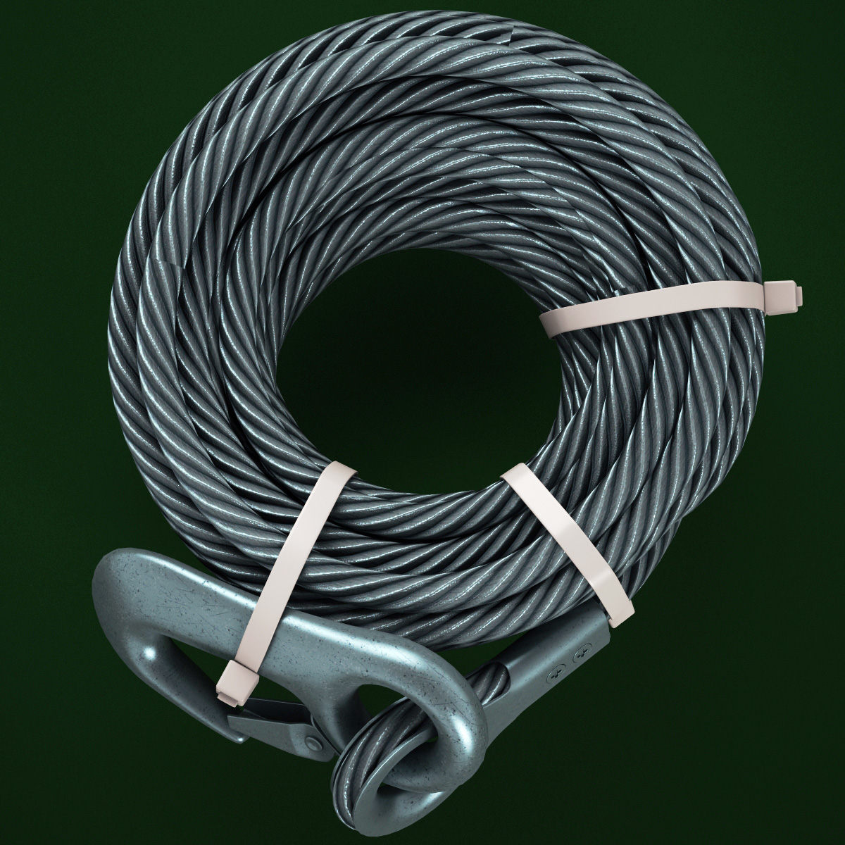
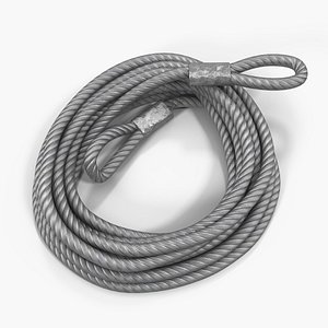
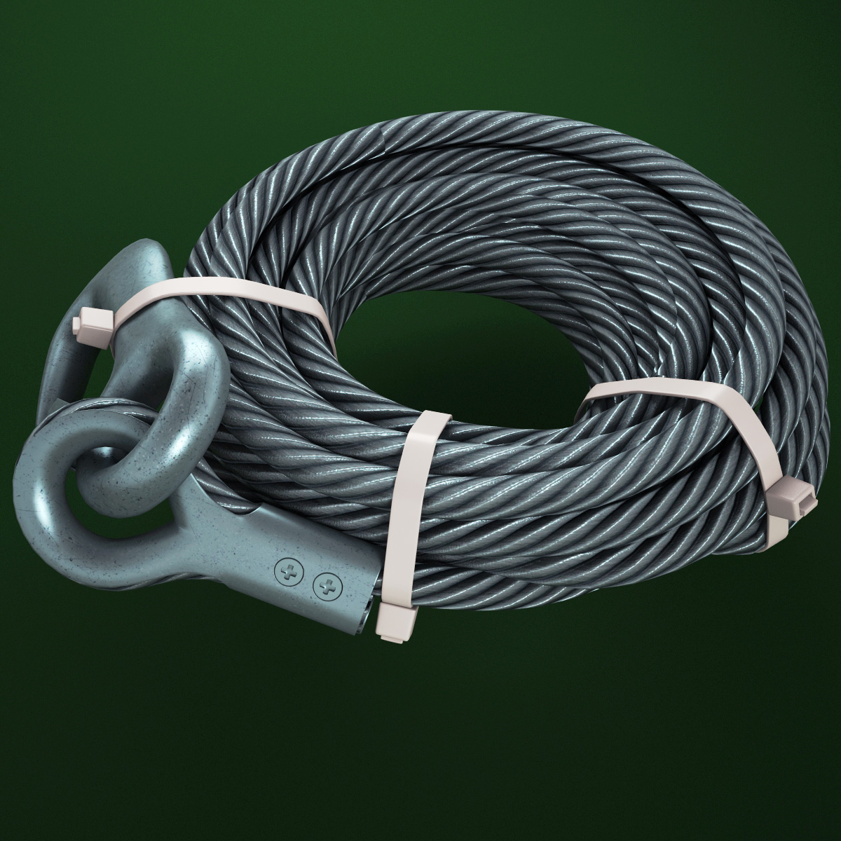
Wire rope consists of several strands of metal wire laid (twisted) into a helix. The term "cable" is often used interchangeably with "wire rope", but narrower senses exist in which "wire rope" refers to diameter larger than 3/8 inch (9.52 mm), whereas sizes smaller than this are designated cable or cords.wrought iron wires were used, but today steel is the main material used for wire ropes.
Historically wire rope evolved from wrought iron chains, which had a record of mechanical failure. While flaws in chain links or solid steel bars can lead to catastrophic failure, flaws in the wires making up a steel cable are less critical as the other wires easily take up the load. Friction between the individual wires and strands, as a consequence of their twist, further compensates for any flaws.
Wire ropes were developed starting with mining hoist applications in the 1830s. Wire ropes are used dynamically for lifting and hoisting in cranes and elevators, and for transmission of mechanical power. Wire rope is also used to transmit force in mechanisms, such as a Bowden cable or the control surfaces of an airplane connected to levers and pedals in the cockpit. Only aircraft cables have WSC (wire strand core). Also, aircraft cables are available in smaller diameters than wire rope. For example, aircraft cables are available in 3/64 in. diameter while most wire ropes begin at a 1/4 in. diameter.suspension bridges or as guy wires to support towers. An aerial tramway relies on wire rope to support and move cargo overhead.
Modern wire rope was invented by the German mining engineer Wilhelm Albert in the years between 1831 and 1834 for use in mining in the Harz Mountains in Clausthal, Lower Saxony, Germany.chains, such as had been used before.
Wilhelm Albert"s first ropes consisted of three strands consisting of four wires each. In 1840, Scotsman Robert Stirling Newall improved the process further.John A. Roebling, starting in 1841 suspension bridge building. Roebling introduced a number of innovations in the design, materials and manufacture of wire rope. Ever with an ear to technology developments in mining and railroading, Josiah White and Erskine Hazard, principal ownersLehigh Coal & Navigation Company (LC&N Co.) — as they had with the first blast furnaces in the Lehigh Valley — built a Wire Rope factory in Mauch Chunk,Pennsylvania in 1848, which provided lift cables for the Ashley Planes project, then the back track planes of the Summit Hill & Mauch Chunk Railroad, improving its attractiveness as a premier tourism destination, and vastly improving the throughput of the coal capacity since return of cars dropped from nearly four hours to less than 20 minutes. The decades were witness to a burgeoning increase in deep shaft mining in both Europe and North America as surface mineral deposits were exhausted and miner had to chase layers along inclined layers. The era was early in railroad development and steam engines having sufficient tractive effort to climb steep slopes were in the future, so incline plane railways were common, and the mining tunnels along inclined shafts between coal layers were just a which came first variant, but where steam engines could not go. This pushed development of cable hoists rapidly in the United States as surface deposits in the Anthracite Coal Region north and south dove deeper every year, and even the rich deposits in the Panther Creek Valley required LC&N Co. to drive their first shafts into lower slopes beginning Lansford and its Schuylkill County twin-town Coaldale.
The German engineering firm of Adolf Bleichert & Co. was founded in 1874 and began to build bicable aerial tramways for mining in the Ruhr Valley. With important patents, and dozens of working systems in Europe, Bleichert dominated the global industry, later licensing its designs and manufacturing techniques to Trenton Iron Works, New Jersey, USA which built systems across America. Adolf Bleichert & Co. went on to build hundreds of aerial tramways around the world: from Alaska to Argentina, Australia and Spitsbergen. The Bleichert company also built hundreds of aerial tramways for both the Imperial German Army and the Wehrmacht.
In the last half of the 19th century, wire rope systems were used as a means of transmitting mechanical powercable cars. Wire rope systems cost one-tenth as much and had lower friction losses than line shafts. Because of these advantages, wire rope systems were used to transmit power for a distance of a few miles or kilometers.
Steel wires for wire ropes are normally made of non-alloy carbon steel with a carbon content of 0.4 to 0.95%. The very high strength of the rope wires enables wire ropes to support large tensile forces and to run over sheaves with relatively small diameters.
In the mostly used parallel lay strands, the lay length of all the wire layers is equal and the wires of any two superimposed layers are parallel, resulting in linear contact. The wire of the outer layer is supported by two wires of the inner layer. These wires are neighbours along the whole length of the strand. Parallel lay strands are made in one operation. The endurance of wire ropes with this kind of strand is always much greater than of those (seldom used) with cross lay strands. Parallel lay strands with two wire layers have the construction Filler, Seale or Warrington.
In principle, spiral ropes are round strands as they have an assembly of layers of wires laid helically over a centre with at least one layer of wires being laid in the opposite direction to that of the outer layer. Spiral ropes can be dimensioned in such a way that they are non-rotating which means that under tension the rope torque is nearly zero.
The open spiral rope consists only of round wires. The half-locked coil rope and the full-locked coil rope always have a centre made of round wires. The locked coil ropes have one or more outer layers of profile wires. They have the advantage that their construction prevents the penetration of dirt and water to a greater extent and it also protects them from loss of lubricant. In addition, they have one further very important advantage as the ends of a broken outer wire cannot leave the rope if it has the proper dimensions.
Stranded ropes are an assembly of several strands laid helically in one or more layers around a core. This core can be one of three types. The first is a fiber core, made up of synthetic material or natural fibers like Sysal. Synthetic fibers are stronger and more uniform but can"t absorb much lubricant. Natural fibers can absorb up to 15% of their weight in lubricant and so protect the inner wires much better from corrosion than synthetic fibers do. Fiber cores are the most flexible and elastic, but have the downside of getting crushed easily. The second type, wire strand core, is made up of one additional strand of wire, and is typically used for suspension. The third type is independent wire rope core (IWRC), which is the most durable in all types of environments.ordinary lay rope if the lay direction of the wires in the outer strands is in the opposite direction to the lay of the outer strands themselves. If both the wires in the outer strands and the outer strands themselves have the same lay direction, the rope is called a lang lay rope (formerly Albert’s lay or Lang’s lay). Regular lay means the individual wires were wrapped around the centers in one direction and the strands were wrapped around the core in the opposite direction.
Multi-strand ropes are all more or less resistant to rotation and have at least two layers of strands laid helically around a centre. The direction of the outer strands is opposite to that of the underlying strand layers. Ropes with three strand layers can be nearly non-rotating. Ropes with two strand layers are mostly only low-rotating.
Stationary ropes, stay ropes (spiral ropes, mostly full-locked) have to carry tensile forces and are therefore mainly loaded by static and fluctuating tensile stresses. Ropes used for suspension are often called cables.
Track ropes (full locked ropes) have to act as rails for the rollers of cabins or other loads in aerial ropeways and cable cranes. In contrast to running ropes, track ropes do not take on the curvature of the rollers. Under the roller force, a so-called free bending radius of the rope occurs. This radius increases (and the bending stresses decrease) with the tensile force and decreases with the roller force.
Wire rope slings (stranded ropes) are used to harness various kinds of goods. These slings are stressed by the tensile forces but first of all by bending stresses when bent over the more or less sharp edges of the goods.
There are technical regulations for the rope drives of cranes, elevators, rope ways and mining installations not exceeding a given tensile force and not falling short of a given diameter ratio D/d of sheave and rope diameters. A general dimensioning method of rope drives (and used besides the technical regulations) calculate the five limits
Donandt force (yielding tensile force for a given bending diameter ratio D/d) - strict limit. The nominal rope tensile force S must be smaller than the Donandt force SD1.
Rope safety factor = minimum breaking force Fmin / nominal rope tensile force S. (ability to resist extreme impact forces) - Fmin/S ≥ 2,5 for simple lifting appliance
Discarding number of wire breaks (detection to need rope replacement) Minimum number of wire breaks on a reference rope length of 30d should be BA30 ≥ 8 for lifting appliance
Optimal rope diameter with the max. rope endurance for a given sheave diameter D and tensile rope force S - For economic reasons the rope diameter should be near to but smaller than the optimal rope diameter d ≤ dopt.
The wire ropes are stressed by fluctuating forces, by wear, by corrosion and in seldom cases by extreme forces. The rope life is finite and the safety is only ensured by inspection for the detection of wire breaks on a reference rope length, of cross-section loss, as well as other failures so that the wire rope can be replaced before a dangerous situation occurs. Installations should be designed to facilitate the inspection of the wire ropes.
Lifting installations for passenger transportation require that a combination of several methods should be used to prevent a car from plunging downwards. Elevators must have redundant bearing ropes and a safety gear. Ropeways and mine hoistings must be permanently supervised by a responsible manager and the rope must be inspected by a magnetic method capable of detecting inner wire breaks.
The end of a wire rope tends to fray readily, and cannot be easily connected to plant and equipment. There are different ways of securing the ends of wire ropes to prevent fraying. The most common and useful type of end fitting for a wire rope is to turn the end back to form a loop. The loose end is then fixed back on the wire rope. Termination efficiencies vary from about 70% for a Flemish eye alone; to nearly 90% for a Flemish eye and splice; to 100% for potted ends and swagings.
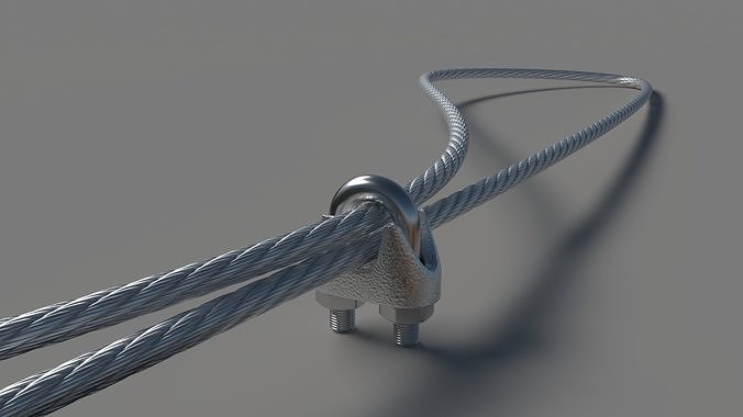
When the wire rope is terminated with a loop, there is a risk that it will bend too tightly, especially when the loop is connected to a device that concentrates the load on a relatively small area. A thimble can be installed inside the loop to preserve the natural shape of the loop, and protect the cable from pinching and abrading on the inside of the loop. The use of thimbles in loops is industry best practice. The thimble prevents the load from coming into direct contact with the wires.
A wire rope clamp, also called a clip, is used to fix the loose end of the loop back to the wire rope. It usually consists of a U-shaped bolt, a forged saddle, and two nuts. The two layers of wire rope are placed in the U-bolt. The saddle is then fitted over the ropes on to the bolt (the saddle includes two holes to fit to the u-bolt). The nuts secure the arrangement in place. Three or more clamps are usually used to terminate a wire rope. As many as eight may be needed for a 2 in (50.8 mm) diameter rope.
There is an old adage; be sure not to "saddle a dead horse." This means that when installing clamps, the saddle portion of the clamp assembly is placed on the load-bearing or "live" side, not on the non-load-bearing or "dead" side of the cable. According to the US Navy Manual S9086-UU-STM-010, Chapter 613R3, Wire and Fiber rope and Rigging, "This is to protect the live or stress-bearing end of the rope against crushing and abuse. The flat bearing seat and extended prongs of the body (saddle) are designed to protect the rope and are always placed against the live end."
An eye splice may be used to terminate the loose end of a wire rope when forming a loop. The strands of the end of a wire rope are unwound a certain distance, and plaited back into the wire rope, forming the loop, or an eye, called an eye splice. When this type of rope splice is used specifically on wire rope, it is called a "Molly Hogan", and, by some, a "Dutch" eye instead of a "Flemish" eye.
Swaging is a method of wire rope termination that refers to the installation technique. The purpose of swaging wire rope fittings is to connect two wire rope ends together, or to otherwise terminate one end of wire rope to something else. A mechanical or hydraulic swager is used to compress and deform the fitting, creating a permanent connection. There are many types of swaged fittings. Threaded Studs, Ferrules, Sockets, and Sleeves are a few examples.
A wedge socket termination is useful when the fitting needs to be replaced frequently. For example, if the end of a wire rope is in a high-wear region, the rope may be periodically trimmed, requiring the termination hardware to be removed and reapplied. An example of this is on the ends of the drag ropes on a dragline. The end loop of the wire rope enters a tapered opening in the socket, wrapped around a separate component called the wedge. The arrangement is knocked in place, and load gradually eased onto the rope. As the load increases on the wire rope, the wedge become more secure, gripping the rope tighter.
Poured sockets are used to make a high strength, permanent termination; they are created by inserting the wire rope into the narrow end of a conical cavity which is oriented in-line with the intended direction of strain. The individual wires are splayed out inside the cone or "capel", and the cone is then filled with molten lead-antimony-tin (Pb80Sb15Sn5) solder or "white metal capping",zincpolyester resin compound.
Paper explores some aspects of 3D modeling of ‘aircraft cable’ as mostly used sling wire rope. First, the 1×19 stainless steel core of ‘aircraft cable’ was investigated. The analysis was carried out by finite element method based computer program. The software used allowed two different types of contacts, including friction. The sling wire rope core was subjected to two different types of axial loading. The obtained results were compared with the solutions calculated from the literature (Costello 2012). Finally, using the advanced modeling techniques, the parametric 3D model of 7×19 ‘aircraft cable’ was analyzed using finite element method, in order to provide a better understanding and, hence, prediction, of the mechanical behavior of the sling wire ropes in lifting processes.
Kastratović, G., & Vidanović, N. (2015). 3D finite element modeling of sling wire rope in lifting and transport processes. Transport, 30(2), 129–134. https://doi.org/10.3846/16484142.2013.816364

3D modeling has changed the way that new ideas are developed and brought to the market. While the concepts that drive design and development are generally the same as they have been, the benefits that 3D modeling offers make it superior to other methods in multiple ways.
Most individuals involved in design or engineering services in any industry are already aware of 3D modeling, even if they don’t know much about it or why it’s so useful. However, sometimes it’s a lack of information that keeps new companies and entrepreneurs from taking advantage of this technology. When that is the case, it’s often pricing and rate information that is the missing piece of the puzzle.
3D modeling and 3D rendering have become staples in many industries. This technology allows ideas to be brought to life quicker than ever before. They also allow the object to be observed and manipulated without putting the work into creating a physical prototype.
3D product modeling services are commonly utilized to develop concepts. They also frequently function as living master drawings in the manufacturing industry. Printed paper drawings are outdated and inaccurate after a single revision, but a file containing a 3D model can simply be saved and shared.
3D renderings could be described as a presentation-worthy image or clip of a 3D model. These clips and images are created and manipulated detail by detail. The models shown within them, the lighting, the texture of surfaces, reflections—all of these factors and more are on the table to work with when creating a 3D rendering. The result is often nearly indistinguishable from a professional photo.
There are many potential benefits that make professional 3D modeling and 3D rendering services so appealing. For one thing, 3D renderings are based on 3D models. If you already have an accurate 3D model of your new product, then getting some photorealistic 3D renderings of it is very simple.
For the most part, 3D models are utilized for design and development purposes. This is true whether you’re dealing with a consumer product, a mechanical item, or a new home. On the other hand, 3D renderings are better suited for presentation and marketing purposes.
In many scenarios, both are far more affordable than alternative options. Many businesses and entrepreneurs find the cost of 3D rendering services to be very appealing as compared to photography.
In the case of outsourcing this type of project, you get to take advantage of another professional’s time, experience, and expertise without having them on salary. Remember, 3D CAD designers and firms tend to charge more than the hourly rate of an employee who does the same job, but once all factors are included, they typically cost less.
Depending on where you look and the specific titles you choose to look at, a full-time 3D modeling service is going to require a salary somewhere between $40,000 and $80,000 per year. That’s just their salary. There are also the taxes to consider, as well as benefits. With competitive benefits packages, the total cost of a full-time employee to a business is usually around double the salary.
For a nice mid-way point of reference, let’s say it would cost at least $100,000 per year to hire a full-time 3D CAD designer for your business. Now that we have a base figure to compare to, let’s take a closer look at what you might expect to pay a freelancer or a firm.
Creating 3D models of new products and ideas is among the things that CAD designers and engineers do best. For product design services, you can expect to pay at least $40 to $60 per hour.
Outsourcing a 3D modeling project is similar to other fields when it comes to pricing. A variety of factors can affect the price. These can include whether you’ve hired a firm or an independent professional, the size of the firm, the size of the project, the complexity of the project, your desired deadline, and even the current workload of that firm or professional.
Rendering is a separate service from 3D modeling. It usually commands a higher hourly rate, although you will see plenty of per-project pricing here as well. You can expect to spend at least $100 per hour for 3D product rendering. Many basic projects take between a few hours and a full workday to complete.
The rates for 3D modeling and 3D rendering with a focus on mechanical design are very similar to those for product design. For 3D modeling work, you’ll be in the neighborhood of $50 per hour or more. 3D rendering for a mechanical design project is at least $100 per hour but may run closer to $200 per hour.
Creating the plans or images of a new home or structure can be a fascinating process for everyone involved. As you may have noticed above, the rates for 3D modeling and 3D rendering with different types of projects are affected by the level of complexity.
One of the things to consider with architectural projects is the fact that multiple models and renderings may be needed over the full course of the design process. So, while the hourly rates may be a little lower, the amount of time that goes into 3D modeling or 3D rendering can be significant. Project TypeHourlyPer Project
As with other types of projects, outsourcing 3D rendering and 3D modeling work to independent professionals or firms is usually a breeze. There will always be some factors that are beyond your control, but here are a few tips to help ensure that things go as smoothly as possible.
If you have a special request, then, by all means, let them know from the start. This will save both you and the 3D solid modeling freelancer time and frustration.
The same concept applies to things that you know you do not want. For example, if you’re after a 3D rendering for your new product but you don’t want a lifestyle type image, then be upfront about it.
This tip ties in with what was just mentioned. Let’s say that you’re seeking a 3D rendering expert and it’s your very first time handling this kind of project. If you don’t know exactly what you need, discuss it with your designer or freelance CATIA engineer.
As long as you can tell them why you want the model or rendering and what you plan to do with it, they’ll be able to provide some great input on what would be the best fit for you.
Time is valuable regardless of which field you’re in, but it’s worth paying even more attention to when you’re getting quotes for a project. If you have planned far enough ahead that you aren’t in a hurry to get your 3D model or rendering, you may be able to get a discount.
If you’re ready to start looking for the right 3D modeling freelance designer for your project, then we’re ready to make that process as easy as possible for you. At Cad Crowd, we have a deep and diverse pool of freelance designers and prototype design engineering services. All of them are experienced and have been vetted.
When you choose to work with a Cad Crowd designer, you also benefit from our standard procedures. For instance, if you find a designer on your own, you may have to relinquish some rights, or you may find yourself worrying about privacy. Both of these are covered with the way we do things. Non-disclosure agreements are used to protect your privacy, and you retain all of the intellectual property rights from the project.
nVent products shall be installed and used only as indicated in nVent"s product instruction sheets and training materials. Instruction sheets are available at www.nvent.com and from your nVent customer service representative. Improper installation, misuse, misapplication or other failure to completely follow nVent"s instructions and warnings may cause product malfunction, property damage, serious bodily injury and death and/or void your warranty.


 8613371530291