
wire rope 3d model free download quotation
Not seeing the model you need? We know how important 3D models are for your projects. If you do not see the file you need, email us at 3D@lukelampco.com and we will ensure that we get it to you ASAP. Our standard turnaround time is two weeks.
Need a different file type?All of our models are offered in STEP, 3D DWG, and SketchUp formats. If you need another file type or you are having issues opening a model, feel free to contact us at 3D@lukelampco.com so that we can assist.
Working on a custom project?When required, we are happy to assist in developing a model for a custom fixture once the project has been initiated. Please inquire for more information.
Need a model for a Tracer Loop installation?Due to the custom nature of Tracer Loop Installations, we regularly assist with model development. If you’re interested in a Tracer Loop install and would like assistance with modeling, please feel free to contact us! To get started, we will ask for the following details:The desired mounting width and drop height for each loop, or
Hoist Central offers a comprehensive library of CAD drawings (DWG) for a wide range of industry-leading hoists. Download hoist system CAD files for use when building with overhead material handling.
CAD drawings for Columbus McKinnon brands: CM Hoists, Yale Hoists, Budgit Hoists and Coffing Hoists are available for download. Click on the logo below to reveal that brand"s library.

Wire rope consists of several strands of metal wire laid (twisted) into a helix. The term "cable" is often used interchangeably with "wire rope", but narrower senses exist in which "wire rope" refers to diameter larger than 3/8 inch (9.52 mm), whereas sizes smaller than this are designated cable or cords.wrought iron wires were used, but today steel is the main material used for wire ropes.
Historically wire rope evolved from wrought iron chains, which had a record of mechanical failure. While flaws in chain links or solid steel bars can lead to catastrophic failure, flaws in the wires making up a steel cable are less critical as the other wires easily take up the load. Friction between the individual wires and strands, as a consequence of their twist, further compensates for any flaws.
Wire ropes were developed starting with mining hoist applications in the 1830s. Wire ropes are used dynamically for lifting and hoisting in cranes and elevators, and for transmission of mechanical power. Wire rope is also used to transmit force in mechanisms, such as a Bowden cable or the control surfaces of an airplane connected to levers and pedals in the cockpit. Only aircraft cables have WSC (wire strand core). Also, aircraft cables are available in smaller diameters than wire rope. For example, aircraft cables are available in 3/64 in. diameter while most wire ropes begin at a 1/4 in. diameter.suspension bridges or as guy wires to support towers. An aerial tramway relies on wire rope to support and move cargo overhead.
Modern wire rope was invented by the German mining engineer Wilhelm Albert in the years between 1831 and 1834 for use in mining in the Harz Mountains in Clausthal, Lower Saxony, Germany.chains, such as had been used before.
Wilhelm Albert"s first ropes consisted of three strands consisting of four wires each. In 1840, Scotsman Robert Stirling Newall improved the process further.John A. Roebling, starting in 1841 suspension bridge building. Roebling introduced a number of innovations in the design, materials and manufacture of wire rope. Ever with an ear to technology developments in mining and railroading, Josiah White and Erskine Hazard, principal ownersLehigh Coal & Navigation Company (LC&N Co.) — as they had with the first blast furnaces in the Lehigh Valley — built a Wire Rope factory in Mauch Chunk,Pennsylvania in 1848, which provided lift cables for the Ashley Planes project, then the back track planes of the Summit Hill & Mauch Chunk Railroad, improving its attractiveness as a premier tourism destination, and vastly improving the throughput of the coal capacity since return of cars dropped from nearly four hours to less than 20 minutes. The decades were witness to a burgeoning increase in deep shaft mining in both Europe and North America as surface mineral deposits were exhausted and miner had to chase layers along inclined layers. The era was early in railroad development and steam engines having sufficient tractive effort to climb steep slopes were in the future, so incline plane railways were common, and the mining tunnels along inclined shafts between coal layers were just a which came first variant, but where steam engines could not go. This pushed development of cable hoists rapidly in the United States as surface deposits in the Anthracite Coal Region north and south dove deeper every year, and even the rich deposits in the Panther Creek Valley required LC&N Co. to drive their first shafts into lower slopes beginning Lansford and its Schuylkill County twin-town Coaldale.
The German engineering firm of Adolf Bleichert & Co. was founded in 1874 and began to build bicable aerial tramways for mining in the Ruhr Valley. With important patents, and dozens of working systems in Europe, Bleichert dominated the global industry, later licensing its designs and manufacturing techniques to Trenton Iron Works, New Jersey, USA which built systems across America. Adolf Bleichert & Co. went on to build hundreds of aerial tramways around the world: from Alaska to Argentina, Australia and Spitsbergen. The Bleichert company also built hundreds of aerial tramways for both the Imperial German Army and the Wehrmacht.
In the last half of the 19th century, wire rope systems were used as a means of transmitting mechanical powercable cars. Wire rope systems cost one-tenth as much and had lower friction losses than line shafts. Because of these advantages, wire rope systems were used to transmit power for a distance of a few miles or kilometers.
Steel wires for wire ropes are normally made of non-alloy carbon steel with a carbon content of 0.4 to 0.95%. The very high strength of the rope wires enables wire ropes to support large tensile forces and to run over sheaves with relatively small diameters.
In the mostly used parallel lay strands, the lay length of all the wire layers is equal and the wires of any two superimposed layers are parallel, resulting in linear contact. The wire of the outer layer is supported by two wires of the inner layer. These wires are neighbours along the whole length of the strand. Parallel lay strands are made in one operation. The endurance of wire ropes with this kind of strand is always much greater than of those (seldom used) with cross lay strands. Parallel lay strands with two wire layers have the construction Filler, Seale or Warrington.
In principle, spiral ropes are round strands as they have an assembly of layers of wires laid helically over a centre with at least one layer of wires being laid in the opposite direction to that of the outer layer. Spiral ropes can be dimensioned in such a way that they are non-rotating which means that under tension the rope torque is nearly zero.
The open spiral rope consists only of round wires. The half-locked coil rope and the full-locked coil rope always have a centre made of round wires. The locked coil ropes have one or more outer layers of profile wires. They have the advantage that their construction prevents the penetration of dirt and water to a greater extent and it also protects them from loss of lubricant. In addition, they have one further very important advantage as the ends of a broken outer wire cannot leave the rope if it has the proper dimensions.
Stranded ropes are an assembly of several strands laid helically in one or more layers around a core. This core can be one of three types. The first is a fiber core, made up of synthetic material or natural fibers like Sysal. Synthetic fibers are stronger and more uniform but can"t absorb much lubricant. Natural fibers can absorb up to 15% of their weight in lubricant and so protect the inner wires much better from corrosion than synthetic fibers do. Fiber cores are the most flexible and elastic, but have the downside of getting crushed easily. The second type, wire strand core, is made up of one additional strand of wire, and is typically used for suspension. The third type is independent wire rope core (IWRC), which is the most durable in all types of environments.ordinary lay rope if the lay direction of the wires in the outer strands is in the opposite direction to the lay of the outer strands themselves. If both the wires in the outer strands and the outer strands themselves have the same lay direction, the rope is called a lang lay rope (formerly Albert’s lay or Lang’s lay). Regular lay means the individual wires were wrapped around the centers in one direction and the strands were wrapped around the core in the opposite direction.
Multi-strand ropes are all more or less resistant to rotation and have at least two layers of strands laid helically around a centre. The direction of the outer strands is opposite to that of the underlying strand layers. Ropes with three strand layers can be nearly non-rotating. Ropes with two strand layers are mostly only low-rotating.
Stationary ropes, stay ropes (spiral ropes, mostly full-locked) have to carry tensile forces and are therefore mainly loaded by static and fluctuating tensile stresses. Ropes used for suspension are often called cables.
Track ropes (full locked ropes) have to act as rails for the rollers of cabins or other loads in aerial ropeways and cable cranes. In contrast to running ropes, track ropes do not take on the curvature of the rollers. Under the roller force, a so-called free bending radius of the rope occurs. This radius increases (and the bending stresses decrease) with the tensile force and decreases with the roller force.
Wire rope slings (stranded ropes) are used to harness various kinds of goods. These slings are stressed by the tensile forces but first of all by bending stresses when bent over the more or less sharp edges of the goods.
There are technical regulations for the rope drives of cranes, elevators, rope ways and mining installations not exceeding a given tensile force and not falling short of a given diameter ratio D/d of sheave and rope diameters. A general dimensioning method of rope drives (and used besides the technical regulations) calculate the five limits
Donandt force (yielding tensile force for a given bending diameter ratio D/d) - strict limit. The nominal rope tensile force S must be smaller than the Donandt force SD1.
Rope safety factor = minimum breaking force Fmin / nominal rope tensile force S. (ability to resist extreme impact forces) - Fmin/S ≥ 2,5 for simple lifting appliance
Discarding number of wire breaks (detection to need rope replacement) Minimum number of wire breaks on a reference rope length of 30d should be BA30 ≥ 8 for lifting appliance
Optimal rope diameter with the max. rope endurance for a given sheave diameter D and tensile rope force S - For economic reasons the rope diameter should be near to but smaller than the optimal rope diameter d ≤ dopt.
The wire ropes are stressed by fluctuating forces, by wear, by corrosion and in seldom cases by extreme forces. The rope life is finite and the safety is only ensured by inspection for the detection of wire breaks on a reference rope length, of cross-section loss, as well as other failures so that the wire rope can be replaced before a dangerous situation occurs. Installations should be designed to facilitate the inspection of the wire ropes.
Lifting installations for passenger transportation require that a combination of several methods should be used to prevent a car from plunging downwards. Elevators must have redundant bearing ropes and a safety gear. Ropeways and mine hoistings must be permanently supervised by a responsible manager and the rope must be inspected by a magnetic method capable of detecting inner wire breaks.
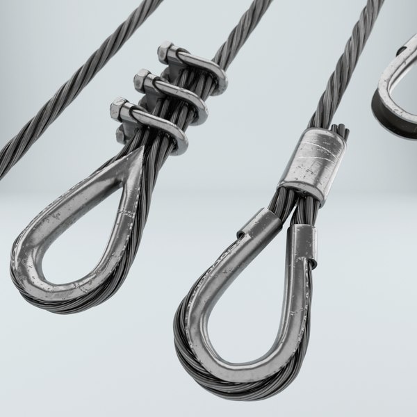
The end of a wire rope tends to fray readily, and cannot be easily connected to plant and equipment. There are different ways of securing the ends of wire ropes to prevent fraying. The most common and useful type of end fitting for a wire rope is to turn the end back to form a loop. The loose end is then fixed back on the wire rope. Termination efficiencies vary from about 70% for a Flemish eye alone; to nearly 90% for a Flemish eye and splice; to 100% for potted ends and swagings.
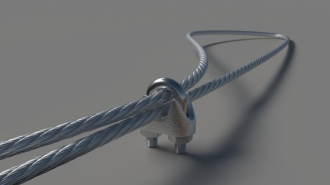
When the wire rope is terminated with a loop, there is a risk that it will bend too tightly, especially when the loop is connected to a device that concentrates the load on a relatively small area. A thimble can be installed inside the loop to preserve the natural shape of the loop, and protect the cable from pinching and abrading on the inside of the loop. The use of thimbles in loops is industry best practice. The thimble prevents the load from coming into direct contact with the wires.
A wire rope clamp, also called a clip, is used to fix the loose end of the loop back to the wire rope. It usually consists of a U-shaped bolt, a forged saddle, and two nuts. The two layers of wire rope are placed in the U-bolt. The saddle is then fitted over the ropes on to the bolt (the saddle includes two holes to fit to the u-bolt). The nuts secure the arrangement in place. Three or more clamps are usually used to terminate a wire rope. As many as eight may be needed for a 2 in (50.8 mm) diameter rope.
There is an old adage; be sure not to "saddle a dead horse." This means that when installing clamps, the saddle portion of the clamp assembly is placed on the load-bearing or "live" side, not on the non-load-bearing or "dead" side of the cable. According to the US Navy Manual S9086-UU-STM-010, Chapter 613R3, Wire and Fiber rope and Rigging, "This is to protect the live or stress-bearing end of the rope against crushing and abuse. The flat bearing seat and extended prongs of the body (saddle) are designed to protect the rope and are always placed against the live end."
An eye splice may be used to terminate the loose end of a wire rope when forming a loop. The strands of the end of a wire rope are unwound a certain distance, and plaited back into the wire rope, forming the loop, or an eye, called an eye splice. When this type of rope splice is used specifically on wire rope, it is called a "Molly Hogan", and, by some, a "Dutch" eye instead of a "Flemish" eye.
Swaging is a method of wire rope termination that refers to the installation technique. The purpose of swaging wire rope fittings is to connect two wire rope ends together, or to otherwise terminate one end of wire rope to something else. A mechanical or hydraulic swager is used to compress and deform the fitting, creating a permanent connection. There are many types of swaged fittings. Threaded Studs, Ferrules, Sockets, and Sleeves are a few examples.
A wedge socket termination is useful when the fitting needs to be replaced frequently. For example, if the end of a wire rope is in a high-wear region, the rope may be periodically trimmed, requiring the termination hardware to be removed and reapplied. An example of this is on the ends of the drag ropes on a dragline. The end loop of the wire rope enters a tapered opening in the socket, wrapped around a separate component called the wedge. The arrangement is knocked in place, and load gradually eased onto the rope. As the load increases on the wire rope, the wedge become more secure, gripping the rope tighter.
Poured sockets are used to make a high strength, permanent termination; they are created by inserting the wire rope into the narrow end of a conical cavity which is oriented in-line with the intended direction of strain. The individual wires are splayed out inside the cone or "capel", and the cone is then filled with molten lead-antimony-tin (Pb80Sb15Sn5) solder or "white metal capping",zincpolyester resin compound.

We are making our products available to you as 3-D volume models free of charge. You can use and open the models, which are in STEP and SAT format, in your CAD program.
Our database contains models of the most frequently requested versions of our products. If the version you are looking for is not included, you can download the individual components of the desired version and put them together yourself. If this is not possible, please send your request to your local SAMSON sales office.
To speed up creation of a model, we kindly ask you to provide precise specifications of the product, such as our quotation or order number including the position number and/or the associated configuration ID of the product.

it looks like you managed to make a length of rope about 2-3 feet long using your machine on that table. If you wanted to make a longer rope using this device in the same amount of space is that possible, or would your ends of the machine simply need to be farther apart?0
It looks like you used some polymer core material in the white support structure, like airplane panels of laminated hexcel, or are the geometric lines just printing artifact? This is a nice visual element regardless, suggesting strength. The gears look a little unreliable though, only because of the plastic -- it looks like the printing temperature was a little high for the gears, they look like the plastic was pushed too far into the liquid regime and settled into their final form with a bit too much freedom. The Pirate"s treasure counterweight looks right though... it is the same material in both, right?
As a final comment, I also make machines and automation components with my 3D printer, and wanted to make sure you knew about the performance polymers available for printing things like gears. PEEK is on the extreme end of things, pricey and not user friendly, but tough enough for a Mars mission. There"s also glass filled nylon (glass microshpheres or silica fume, I think), carbon fiber dust filled nylon (better properties than the carbon filled PLA), also either POM or polycarbonate make excellent gears even down to 0.5 modulus with reliable results, these have teeth about 1/5 the size of your black ones.
After more printing experience, I look back on the comment I made to you with a little shame, it looks perfect on second and more competent analysis. I also want to offer you a HUGE thanks! Your machine is amazing for a niche application of audiophile wires, patch cables, anything carrying a signal from here to there... What do I mean? Well, if you open your Ethernet cable, you will see 4 twisted pairs. Why do this? Electricity and magnetism are inseparable, and a straight line carrying an electrical signal, generates a magnetic field on the normal (90º) to the vector of electrical signal travel. OK, so? this magnetism also can pair up with other random fields floating about, beamed from radio towers, your microwave, wifi router, speakers, etc. basically, if we could see all of it, it would be a Timothy Leary lolapalloza of kaleidoscopic chaos, moving at crazy speeds. OK, we can call all that a source of noise. Twisting the pairs of wires sort of balances it out. sending the signal down multiple wires, and twisting them in a more complex manner, like 5 lines interbraided to carry 1 signal on 2 and ground on 3 or vice versa, on silver filament wire, in thin teflon tubes, each shielded with braided copper mesh, then sleeved stylishly in braided wire wrap, and, wait for it.... fed into your machine! I know how to sell this, in other words. I would like to invite you to join me on this, since you are the source of tech, I can either offer you some royalties or a partnership. Don"t get too excited, I can see this as a good easy sideline, but not a trophy real estate buyer. If this is interesting, please contact me directly at mark at consultchem dot info. This isn"t a polite shakedown for venture capital, I plan to ask for that together with you from any number of third parties that do this for a living.
Impressive! I"ve printed this and am beginning to use it to make miniature bell ropes, complete with woolly sallies. A bit rough at the moment - but I"m learning!
1: The holes behind the bearing housings aren"t big enough. They are a bare 10mm across. It needs 11.5mm or thereabouts to allow a nut to spin freely as they need to do.
5: When buying aluminium angle, they came in 1m lengths. I decided to get two, rather than cut one. Just as well I did. The traveller ("rope tower") needs a great deal further to move than the 370mm length quoted. Laying up a rope from fibres (not simply cable-laying as in the example), you get at leat 20% shrink. So a 3m. finished cord is going to need to start at 4m and the traveller will move at least a metre.
Having said all of that, it"s a great bit of kit. I suspect I"ll need to make a new top (what you call a "Rope Seperator" qv) to accommodate the thicker woven sally bits - and I think that, though I have more than doubled the counterweight to account for the pulley system, I think it could go heavier.
As you use it, if you don"t know, do some research on rope making. Find out the history of it all and, above all, try to source materials to really make a rope, rather than just re-lay string! In particular, look at the difference between left- and right-hand lay. At the components of a rope and see how a filament becomes a yarn and a yarn becomes a strand - and how "S" twist alternates with "Z" twist. All fascinating stuff!
Hmmm... I"d be careful with that. If you use the cable as one of the strands, I think you"d be stressing it too much. With uneven strands, it"ll look a rather odd rope anyway.
If you were to drill a suitable size hole in the cord slider (called a "top", I believe), you could probably wrap three rope strands around a central electric wire. That will still put quite a twist into the wire. It would be worth experimenting with a light electric cable that is, itself, twisted and then to arrange your rope maker to give a left-handed (anticlockwise) twist by running your drill in reverse. That will then UNtwist the cable, which will stress it a little less. All you can do is to experiment - but be gentle with the electrics!ReplyUpvote
I have seen some rope making in different places but having a how to along with files all in one instructable is a game changer for someone like me, who is interested, but the barriers of making, finding etc would mean a proper investigation wouldn"t happen. .
Very interesting indestructible! What is your 3d printer? I do not have a 3d printer, but am looking at getting one some day as I see more and more uses for it. Good job building this instuction and the video.. seeing helps a lot I think.


 8613371530291