
wire rope aluminium ferrules free sample
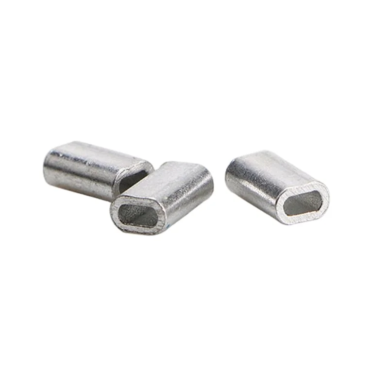
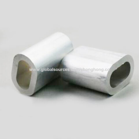
Our fishing wire single crimp sleeves are made of quality aluminum. No burrs, no sharp edges, corrosion resistant and with high strength, they are nicely crafted. Light, small and cute thing to connect mono and wire leader or other leader materials. Once connected to the line or wire, it ensure a firm hold.
All of Talurit’s ferrules are produced seamless for added safety. All aluminum ferrules from size 8 & up are fully traceable (ISO 9001), marked with size, type & Manufacturing batch number.
The T-ferrule is for usage on wire ropes with a maximum tensile grade up to 1960 while the TS (shorter version) is for tensile grade up to 1770. For applications above 2160, T-LOC must be used together with the T-ferrule.
The T aluminum turnback ferrules are the most commonly used ferrules in the market, they have a vast variety of applications especially in the lifting gear industry. The T ferrule are thoroughly specified and very well defined for many different wire rope applications. The ferrules can be used for fiber core, single layer wire ropes, steel core single layer wire ropes, rotation resistant wire ropes and some spiral strand ropes.
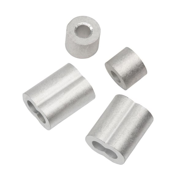
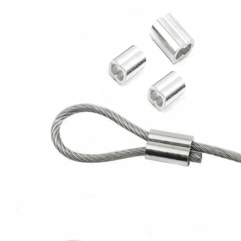
Aluminium ferrules are a popular choice for securing wire rope assemblies. You can find a wide variety of custom-made options. We can fit any aluminium ferrule sizes you require and create a bespoke assembly to tackle various lifting tasks.
Aluminium ferrules are cost-effective and practical. They provide the perfect way to secure a steel wire rope fitting in place with a tight compression fit. This ensures that the rope remains resilient when handling payloads of various sizes.
The main drawback is that aluminium is more susceptible to corrosion than some other materials. Especially in environments where electro-chemical contamination is likely. Check out our full line-up of cable and wire rope ferrules to find the copper, carbon and stainless steel alternatives.

2. (A) All goods supplied by us shall remain the sole and absolute property of us until such time as the customer shall have paid us the agreed price together with the full price of any other goods the subject of any other contract with us.
8. If the buyer shall make default in or commit a breach of the contract, or of any other of his obligations to the seller, or if any distress or execution shall be levied upon the buyer’s property or assets, or if the buyer shall make or offer to make any arrangement or composition with creditors, or commit any act of bankruptcy, or if any petition or receiving order in bankruptcy shall be presented or made against him if the buyer is a limited company and any resolution or petition to wind-up such company’s business (other than for the purpose or amalgamation or reconstruction) shall be passed or presented, or if a receiver of such company’s undertaking, property or assets or any other part thereof shall be appointed, the seller shall have the right forthwith to determine any contract then subsisting and upon written notice of such determination being posted to the buyer’s last known address any subsisting contracts shall be deemed to have been determined without prejudice to any claim or right the seller may otherwise make or exercise.
A pressurized air hose in case of hose failure or accidental uncoupling could cause the hose assembly to whip violently due to the sudden release of energy. The lethal whipping hose lethal can create a potentially dangerous situation. In such a scenario Superex whipcheck safety cables ensure safety from injury and property damage.
Our products had exported to many regions like North America, South America, Europe, Africa, Asia, Middle East, etc. Our factory professional made steel wire rope ,steel cable ,aircraft ,china,hardware over 20 years experience .20000tons annual yeild are a solid gurantee of qualified products for you. Guarantee excellent quality. We also could do OEM services, can well meet clients’ needs and requests.
A pressurized air hose in case of hose failure or accidental uncoupling could cause the hose assembly to whip violently due to the sudden release of energy. The lethal whipping hose lethal can create a potentially dangerous situation. In such a scenario Superex whipcheck safety cables ensure safety from injury and property damage.
Our products had exported to many regions like North America, South America, Europe, Africa, Asia, Middle East, etc. Our factory professional made steel wire rope ,steel cable ,aircraft ,china,hardware over 20 years experience .20000tons annual yeild are a solid gurantee of qualified products for you. Guarantee excellent quality. We also could do OEM services, can well meet clients" needs and requests.
In stricter senses, the term wire rope refers to a diameter larger than 9.5 mm (3⁄8 in), with smaller gauges designated cable or cords.wrought iron wires were used, but today steel is the main material used for wire ropes.
Historically, wire rope evolved from wrought iron chains, which had a record of mechanical failure. While flaws in chain links or solid steel bars can lead to catastrophic failure, flaws in the wires making up a steel cable are less critical as the other wires easily take up the load. While friction between the individual wires and strands causes wear over the life of the rope, it also helps to compensate for minor failures in the short run.
Wire ropes were developed starting with mining hoist applications in the 1830s. Wire ropes are used dynamically for lifting and hoisting in cranes and elevators, and for transmission of mechanical power. Wire rope is also used to transmit force in mechanisms, such as a Bowden cable or the control surfaces of an airplane connected to levers and pedals in the cockpit. Only aircraft cables have WSC (wire strand core). Also, aircraft cables are available in smaller diameters than wire rope. For example, aircraft cables are available in 1.2 mm (3⁄64 in) diameter while most wire ropes begin at a 6.4 mm (1⁄4 in) diameter.suspension bridges or as guy wires to support towers. An aerial tramway relies on wire rope to support and move cargo overhead.
Modern wire rope was invented by the German mining engineer Wilhelm Albert in the years between 1831 and 1834 for use in mining in the Harz Mountains in Clausthal, Lower Saxony, Germany.chains, such as had been used before.
Wilhelm Albert"s first ropes consisted of three strands consisting of four wires each. In 1840, Scotsman Robert Stirling Newall improved the process further.John A. Roebling, starting in 1841suspension bridge building. Roebling introduced a number of innovations in the design, materials and manufacture of wire rope. Ever with an ear to technology developments in mining and railroading, Josiah White and Erskine Hazard, principal ownersLehigh Coal & Navigation Company (LC&N Co.) — as they had with the first blast furnaces in the Lehigh Valley — built a Wire Rope factory in Mauch Chunk,Pennsylvania in 1848, which provided lift cables for the Ashley Planes project, then the back track planes of the Summit Hill & Mauch Chunk Railroad, improving its attractiveness as a premier tourism destination, and vastly improving the throughput of the coal capacity since return of cars dropped from nearly four hours to less than 20 minutes. The decades were witness to a burgeoning increase in deep shaft mining in both Europe and North America as surface mineral deposits were exhausted and miners had to chase layers along inclined layers. The era was early in railroad development and steam engines lacked sufficient tractive effort to climb steep slopes, so incline plane railways were common. This pushed development of cable hoists rapidly in the United States as surface deposits in the Anthracite Coal Region north and south dove deeper every year, and even the rich deposits in the Panther Creek Valley required LC&N Co. to drive their first shafts into lower slopes beginning Lansford and its Schuylkill County twin-town Coaldale.
The German engineering firm of Adolf Bleichert & Co. was founded in 1874 and began to build bicable aerial tramways for mining in the Ruhr Valley. With important patents, and dozens of working systems in Europe, Bleichert dominated the global industry, later licensing its designs and manufacturing techniques to Trenton Iron Works, New Jersey, USA which built systems across America. Adolf Bleichert & Co. went on to build hundreds of aerial tramways around the world: from Alaska to Argentina, Australia and Spitsbergen. The Bleichert company also built hundreds of aerial tramways for both the Imperial German Army and the Wehrmacht.
In the last half of the 19th century, wire rope systems were used as a means of transmitting mechanical powercable cars. Wire rope systems cost one-tenth as much and had lower friction losses than line shafts. Because of these advantages, wire rope systems were used to transmit power for a distance of a few miles or kilometers.
Steel wires for wire ropes are normally made of non-alloy carbon steel with a carbon content of 0.4 to 0.95%. The very high strength of the rope wires enables wire ropes to support large tensile forces and to run over sheaves with relatively small diameters.
In the mostly used parallel lay strands, the lay length of all the wire layers is equal and the wires of any two superimposed layers are parallel, resulting in linear contact. The wire of the outer layer is supported by two wires of the inner layer. These wires are neighbors along the whole length of the strand. Parallel lay strands are made in one operation. The endurance of wire ropes with this kind of strand is always much greater than of those (seldom used) with cross lay strands. Parallel lay strands with two wire layers have the construction Filler, Seale or Warrington.
In principle, spiral ropes are round strands as they have an assembly of layers of wires laid helically over a centre with at least one layer of wires being laid in the opposite direction to that of the outer layer. Spiral ropes can be dimensioned in such a way that they are non-rotating which means that under tension the rope torque is nearly zero. The open spiral rope consists only of round wires. The half-locked coil rope and the full-locked coil rope always have a centre made of round wires. The locked coil ropes have one or more outer layers of profile wires. They have the advantage that their construction prevents the penetration of dirt and water to a greater extent and it also protects them from loss of lubricant. In addition, they have one further very important advantage as the ends of a broken outer wire cannot leave the rope if it has the proper dimensions.
Stranded ropes are an assembly of several strands laid helically in one or more layers around a core. This core can be one of three types. The first is a fiber core, made up of synthetic material or natural fibers like sisal. Synthetic fibers are stronger and more uniform but cannot absorb much lubricant. Natural fibers can absorb up to 15% of their weight in lubricant and so protect the inner wires much better from corrosion than synthetic fibers do. Fiber cores are the most flexible and elastic, but have the downside of getting crushed easily. The second type, wire strand core, is made up of one additional strand of wire, and is typically used for suspension. The third type is independent wire rope core (IWRC), which is the most durable in all types of environments.ordinary lay rope if the lay direction of the wires in the outer strands is in the opposite direction to the lay of the outer strands themselves. If both the wires in the outer strands and the outer strands themselves have the same lay direction, the rope is called a lang lay rope (from Dutch langslag contrary to kruisslag,Regular lay means the individual wires were wrapped around the centers in one direction and the strands were wrapped around the core in the opposite direction.
Multi-strand ropes are all more or less resistant to rotation and have at least two layers of strands laid helically around a centre. The direction of the outer strands is opposite to that of the underlying strand layers. Ropes with three strand layers can be nearly non-rotating. Ropes with two strand layers are mostly only low-rotating.
Stationary ropes, stay ropes (spiral ropes, mostly full-locked) have to carry tensile forces and are therefore mainly loaded by static and fluctuating tensile stresses. Ropes used for suspension are often called cables.
Track ropes (full locked ropes) have to act as rails for the rollers of cabins or other loads in aerial ropeways and cable cranes. In contrast to running ropes, track ropes do not take on the curvature of the rollers. Under the roller force, a so-called free bending radius of the rope occurs. This radius increases (and the bending stresses decrease) with the tensile force and decreases with the roller force.
Wire rope slings (stranded ropes) are used to harness various kinds of goods. These slings are stressed by the tensile forces but first of all by bending stresses when bent over the more or less sharp edges of the goods.
Technical regulations apply to the design of rope drives for cranes, elevators, rope ways and mining installations. Factors that are considered in design include:
Donandt force (yielding tensile force for a given bending diameter ratio D/d) - strict limit. The nominal rope tensile force S must be smaller than the Donandt force SD1.
The wire ropes are stressed by fluctuating forces, by wear, by corrosion and in seldom cases by extreme forces. The rope life is finite and the safety is only ensured by inspection for the detection of wire breaks on a reference rope length, of cross-section loss, as well as other failures so that the wire rope can be replaced before a dangerous situation occurs. Installations should be designed to facilitate the inspection of the wire ropes.
Lifting installations for passenger transportation require that a combination of several methods should be used to prevent a car from plunging downwards. Elevators must have redundant bearing ropes and a safety gear. Ropeways and mine hoistings must be permanently supervised by a responsible manager and the rope must be inspected by a magnetic method capable of detecting inner wire breaks.
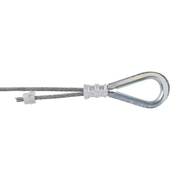
The end of a wire rope tends to fray readily, and cannot be easily connected to plant and equipment. There are different ways of securing the ends of wire ropes to prevent fraying. The common and useful type of end fitting for a wire rope is to turn the end back to form a loop. The loose end is then fixed back on the wire rope. Termination efficiencies vary from about 70% for a Flemish eye alone; to nearly 90% for a Flemish eye and splice; to 100% for potted ends and swagings.
When the wire rope is terminated with a loop, there is a risk that it will bend too tightly, especially when the loop is connected to a device that concentrates the load on a relatively small area. A thimble can be installed inside the loop to preserve the natural shape of the loop, and protect the cable from pinching and abrading on the inside of the loop. The use of thimbles in loops is industry best practice. The thimble prevents the load from coming into direct contact with the wires.
A wire rope clip, sometimes called a clamp, is used to fix the loose end of the loop back to the wire rope. It usually consists of a U-bolt, a forged saddle, and two nuts. The two layers of wire rope are placed in the U-bolt. The saddle is then fitted to the bolt over the ropes (the saddle includes two holes to fit to the U-bolt). The nuts secure the arrangement in place. Two or more clips are usually used to terminate a wire rope depending on the diameter. As many as eight may be needed for a 2 in (50.8 mm) diameter rope.
The mnemonic "never saddle a dead horse" means that when installing clips, the saddle portion of the assembly is placed on the load-bearing or "live" side, not on the non-load-bearing or "dead" side of the cable. This is to protect the live or stress-bearing end of the rope against crushing and abuse. The flat bearing seat and extended prongs of the body are designed to protect the rope and are always placed against the live end.
An eye splice may be used to terminate the loose end of a wire rope when forming a loop. The strands of the end of a wire rope are unwound a certain distance, then bent around so that the end of the unwrapped length forms an eye. The unwrapped strands are then plaited back into the wire rope, forming the loop, or an eye, called an eye splice.
A Flemish eye, or Dutch Splice, involves unwrapping three strands (the strands need to be next to each other, not alternates) of the wire and keeping them off to one side. The remaining strands are bent around, until the end of the wire meets the "V" where the unwrapping finished, to form the eye. The strands kept to one side are now re-wrapped by wrapping from the end of the wire back to the "V" of the eye. These strands are effectively rewrapped along the wire in the opposite direction to their original lay. When this type of rope splice is used specifically on wire rope, it is called a "Molly Hogan", and, by some, a "Dutch" eye instead of a "Flemish" eye.
Swaging is a method of wire rope termination that refers to the installation technique. The purpose of swaging wire rope fittings is to connect two wire rope ends together, or to otherwise terminate one end of wire rope to something else. A mechanical or hydraulic swager is used to compress and deform the fitting, creating a permanent connection. Threaded studs, ferrules, sockets, and sleeves are examples of different swaged terminations.
A wedge socket termination is useful when the fitting needs to be replaced frequently. For example, if the end of a wire rope is in a high-wear region, the rope may be periodically trimmed, requiring the termination hardware to be removed and reapplied. An example of this is on the ends of the drag ropes on a dragline. The end loop of the wire rope enters a tapered opening in the socket, wrapped around a separate component called the wedge. The arrangement is knocked in place, and load gradually eased onto the rope. As the load increases on the wire rope, the wedge become more secure, gripping the rope tighter.
Poured sockets are used to make a high strength, permanent termination; they are created by inserting the wire rope into the narrow end of a conical cavity which is oriented in-line with the intended direction of strain. The individual wires are splayed out inside the cone or "capel", and the cone is then filled with molten lead-antimony-tin (Pb80Sb15Sn5) solder or "white metal capping",zincpolyester resin compound.
Donald Sayenga. "Modern History of Wire Rope". History of the Atlantic Cable & Submarine Telegraphy (atlantic-cable.com). Archived from the original on 3 February 2014. Retrieved 9 April 2014.

Construction The size and number of wires in each strand, as well as the size and number of strands in the rope greatly affect the characteristics of the rope. In general, a large number of small-size wires and strands produce a flexible rope with good resistance to bending fatigue. The rope construction is also important for tensile load (static, live or shock) abrasive wear, crushing, corrosion and rotation. The number of strands and wires will influence the flexibility, fatigue and wear resistance of any given wire rope. Rope selection is often a compromise. Generally the more load bearing wires in the rope the greater the flexibility, however the smaller the wires the less abrasion resistance. For example, the same nominal diameter 7 x 7 wire would be less flexible than a 7 x 19 wire, hence a large number of small size wire and strands produce a flexible rope with good resistance to bending fatigue wear. The construction of wire rope is defined by the number of outer strands (first number), and the number of wires within that strand (second number) and then by the arrangement of the wires in each strand (shown in brackets). The wires in each strand can be arranged in several ways, for example a 6 x 19 construction the 19 wires in each strand are laid 9 around 9 around 1 centre wire.
Endurance Dyform 6 20-22// Usha Martin Crane Wire Rope 23-25// Wire Rope Slings Overview 26 // Tri-flex Wire Rope Slings 27 // Wire Rope Terminations 27 //
Core The core of a steel wire rope serves as a foundation for the strands, providing stability by keeping them in place throughout the life of the rope. Wire ropes can be supplied with either a fibre or wire core. Grade Wire rope can be manufactured in different steel grades, which directly affects the Minimum Breaking Force, (MBF). The higher the grade the higher the MBF. Common wire grades include: 1570, 1770, 1960 and 2070 Finish Wire Ropes can be supplied as Black (self-colour), Galvanised or Stainless Steel. Wire rope is lubricated at the time of manufacture, to help reduce friction between wires and strands, and the friction between the rope and drum or sheave. In addition, the lubrication retards corrosion and inhibits possible rotting of the fibre core.
RHOL Right Hand Ordinary Lay LHOL Left Hand Ordinary Lay RHLL Right Hand Lang’s Lay LHLL Left Hand Lang’s Lay Pref Preformed Post Postformed WRC Wire Rope Core WSC Wire Strand Core FC Fibre Core FW Filler Wire Strand Construction D or d Diameter (in millimetres)
Rotating or Non-Rotating Rotation resistant wire ropes are manufactured to resist rotation under load and are suitable for crane use and where long lengths are required.
Clamping Wire Rope To ensure complete safety, it is imperative that wire ropes are clamped correctly. The diagrams below are a guide only. Please refer to the relevant Australian Standards AS 2076 for further information.
Correct Spooling of Steel Wire Rope on Drum It is imperative to correctly spool wire rope onto a drum. Improper spooling induces torque within the rope, which in turn reduces the life of the rope.
tension to avoid any slack on inner layers that can be crushed or nicked against the groove walls by outer layers. In general, the tighter the line, the better the spooling, but the rope should be tensioned with at least 2% of the breaking load or 10% of the working load.
Lubricating Steel Wire Ropes All steel wire ropes supplied by Robertsons are lubricated at the time of manufacture, however, periodic lubrication with good quality acid free and moisture free lubricant during use is required to ensure best performance. The following are accepted ways to lubricate wire ropes during use.
Steel Wire Rope Cutting Procedure Hand cutters for cutting ropes up to 8mm in diameter are sufficient. Mechanical or hydraulic cutters will be required for wire ropes with larger diameters.
Careless cutting can result in the balance of tension in the rope being destroyed. In every case, each side of the cut must be correctly seized to prevent strand
C: Both ends of the seizing wire are then pulled tight and twisted together for a length of one rope diameter. The twisted connection is then hammered into a strand valley.
Typical Steel Wire Rope Failures Steel wire rope is tough and durable, however eventually it will reach the end of its safe service life. Below are some examples of typical damage and deterioration. Steel wire ropes should be inspected every 12 months.
Storing Steel Wire Ropes Ensure steel wire rope is stored in a weather-proof storage space. If wire rope is to be kept unused for a considerable amount of time, it must be protected from the elements. The ideal storage area is a dry, well-ventilated building or shed. Avoid closed, unheated, tightly sealed buildings or enclosures because condensation will form when warm, moist outside (ambient) air envelopes the colder rope. Although wire rope is protected by a lubricant, this is not totally effective since condensation can still occur within the small sections between strands and wires, thereby causing corrosion problems. Ensure the reels are kept up off the ground, or are placed on a concrete floor. • Reels should be mounted on jacks or placed on a swift (with a brake arrangement) and care taken to see that the reel rotates as the rope unwinds • Ensure clearance for free rotation of the reel when the rope end is pulled and maintain continuous tension during haul off Correct Handling of Steel Wire Ropes Incorrect handling of steel wire ropes can cause kinking or loops Ropes should be stored in a clean dry place under cover. Reels or coils should be kept off the ground and supported by timber. They should also be examined periodically and rope dressing renewed as required. 1) Unreeling and Uncoiling Reels should be mounted on jacks and care taken to see that the reel rotates as the rope unwinds. Timber should be applied as a lever to one of the flanges to act as a brake, keeping the rope tight and preventing the reel from over- running. When the ropes are supplied in coils a turntalbe or swift should be employed and the free end pulled out with event tension as the swift, or turnatable revolve. Over-winding should be avoided at all times to obviate kinking. Coils may also be unwound by securing the free outside end of the rope and then rolling the coil along the ground; care being taken at all times to ensure that the coil is held firmly together, avoiding tight coils or kinks. Ropes should be stored in a clean dry place under cover. Reels or coils should be kept off the ground and supported by timber. They should also be examined periodically and rope dressing r newed as required. 1) Unreeling and Uncoiling Reels should be mounted on jacks and care taken to see that th reel ro ates as the rope unwinds. Timber should be applied as a lever t one of the flanges to act as a brake, keeping the rope tight and pr ve ting the reel from over- run ing. When the ropes are supplied in coils a turntalbe or swift should b employed and the fre end pulled out with vent tension as the swift, or turnatable revolve. Over-winding should be avoided t all times to obviate kinking. Coils may also be unwound by securing the free outside end of the rope and then rolling the coi along the ground; care being taken t all times to ensure that the coil is held firmly together, avoiding tight coils or kinks. Ropes should be stored in a clean ry lace under cove . R ls or coils shoul be k pt off the ground and supported by timber. They should also be examined periodically and rope dressing renewed as required. 1) Unreeling and Unc iling Re s should be mounted on jacks and c re taken to se that the reel r tates as the rope u winds. Timbe should be appl ed as a lever to one of the flanges to act as a brake, keeping the rope tight and preventing the reel from over- running. When the rope are supplied in coils a turntalbe or swift employed and the free end pulled out w th event tension as the swift, or tur atabl rev lve. Ov r-winding shoul be av ided at all t mes to obviate kinking. Coils may also be unwound by sec ing the fr e out id end of th rope and the rolling the c il along the ground; care being taken at all times to ensure that the coil is held firmly together, avoiding tight coils or kinks. Ropes should be stored in a clean dry place under cover. Reels or coils should be kept off the ground and supported by timber. They should also be examined periodically and rope dressing renewed a required. 1) Unreeling and Uncoiling Reels should be mounted on jacks and care taken to see that the reel rotates as the rope unwinds. Timber should be applied as a lever to one of the flanges to act as a brake, keeping the rope tight and preventing the reel from over- running. When the ropes are supplied in coils a turntalbe or swift should be employed and the free end pulled out with event tension as the swift, or turnatable revolve. Over-winding should be avoided at all times to obviate kinking. Coils may also be unwound by securing the free outside end of the rope and then rolling the coil along the ground; care being taken at all times to ensure that the coil is held firmly together, avoiding tight coils or kinks. Ropes should be stored in a clean dry place under cove . R els or coils should be k pt off the ground and supported by timber. They should also be xamined p riodically and rope dressing renewed as required. 1) Unreeling and U c iling Reels should be mounted on jacks and care taken to see that the reel tates as the rope u winds. Timb r should be appl ed as a lev r to ne of the flanges to act as a brake, keeping the rope tight and prev nti g the reel from over- running. When the rope are supplied in coils a turntalbe or swift empl y d and the free end pull d out with event tensi n as the swift, or t r at ble rev lve. Ov r-winding sh uld be avoided at all times to bviate kinki g. Coils may also be unwound by securing the free out id nd of the rop and then rollin the coil a ong the ground; care being taken at ll times to ensure that the coil is held firmly together, avoiding tight coils or kinks. forming in the steel wire rope, causing permanent damage. Below is a summary of the correct way to handle steel wire rope:
Although the steel wire rope is lubricated at the time of manufacture, a suitable lubricant should be applied every three months. The reels containing the steel wire ropes should also be rotated 90 degrees every three months.
11. Handling and Care of Wire Ropes 1. Handling and Care of Wire Ropes 11. Handling and Care of Wire Ropes 11. Handling and Care of Wire Ropes 1 . Handling and Care of Wire Rop s
2) Seizings It is important that before cutting ropes are properly seized with annealed mild steel wire or strand to avoid slack wires and possible rope distortion. 2) Se zings It s important that before cutting ropes are properly s ized with annealed mild steel wire or strand to avoid slack wires and possible rope distortion. 2) Seizings It is important that bef re cutting ropes are properly seized with annealed mild steel wire or strand to avoid slack wires and possible rope distortion. 2) Seizings It is important that before cutting ropes are properly seized with annealed mild steel wire or strand to avoid slack wires and possible rope distortion. 2) Seiz ngs It is important that before cutting ropes are properly seized with annealed mild steel wire or strand to avoid slack wires and possible rope distortion.
Wire Rope Terminations Hand spliced or machine swaged slings, with your choice of terminations, can be manufactured and tested (if required) on our premises at short notice. All slings and assemblies are permanently marked with safe working loads, based on a 5:1 factor of safety. Machine Swaging Aluminium Ferrules Sizes 2mm – 52mm. Copper Ferrules Sizes 2mm – 10mm Steel Ferrules Sizes 9mm – 75mm Swage Sockets Sizes 3mm – 52mm Hand Splicing from 2mm – 75mm dia
Galvanised Wire RHOL 63 41.8 Galvanised Wire RHOL 90 60.2 Galvanised Wire RHOL 107 70.7 Galvanised Wire RHOL 124 82 Galvanised Wire RHOL 161 107 Galvanised Wire RHOL 204 135 Galvanised Wire RHOL 252 167 Galvanised Wire RHOL 304 202 Galvanised Wire RHOL 363 241 Galvanised Wire RHOL 426 283 Galvanised Wire RHOL 493 328 Galvanised Wire RHOL 644 428 Galvanised Wire RHOL 816 542 Galvanised Wire RHOL 911 604 Galvanised Wire RHOL 1009 669 Galvanised Wire RHOL 1220 810 Galvanised Wire RHOL 1700 1110
Galvanised Wire RHOL 18.9 10.4 Galvanised Wire RHOL 27.2 14.3 Galvanised Wire RHOL 37.2 20.2 Galvanised Wire RHOL 47.5 25.66 Galvanised Wire RHOL 59.3 32 Galvanised Wire RHOL 73 39.4
POWERFORM® 8/8P • A high strength eight strand rope with plastic impregnated core ideal for situations where longer service life is required • High fatigue life resulting from the unique compaction process • Maximum resistance to crushing. Recommended for multi-layer spooling operations
• A sample of rope from each production batch is tested to destruction • Greater surface contact area resulting from the eight strand construction and compacted finish give longer rope life and reduced sheave wear • Optional plastic impregnation of the steel core. (P) signifies full plastic impregnation of the steel core.
POWERFORM® 35/35P • Superior strength and resistance to rotation • Suitable for use on single part and multi-part hoist reeving systems • High fatigue life due to unique compaction process • A sample of rope from each production batch is tested to destruction
52 2256.0 230.0 *Mass per unit length of POWERFORM 35P increases by approx. 3%. Note: • POWERFORM 35P is available on special request and prior confirmation. • Rope sizes and Breaking Force not shown in the standard table, may be available on request and prior confirmation.
Note: • POWERFORM 8P is available for rope diameter 16mm and above on special request and prior confirmation. • Rope sizes and Breaking Force not shown in the standard table, may be available on request and prior confirmation.
POWERFORM® 6/6P • A high strength rugged six strand rope ideal for situations where longer service life is required • Can be substituted for any six strand construction to improve service life • High fatigue life due to unique compaction process • A sample of rope from each production batch is tested to destruction
Typical Steel Wire Rope Sling Description Hand spliced or machine swaged slings, with your choice of terminations, can be manufactured and tested (if required) on our premises at short notice. All slings and assemblies are permanently marked with safe working loads, based on a 5:1 factor of safety.
Machine Swaging Aluminium Ferrules Sizes 2mm – 52mm Copper Ferrules Sizes 2mm – 10mm Steel Ferrules Sizes 9mm – 75mm Swage Sockets Sizes 3mm – 52mm Hand Splicing from 2mm – 75mm dia
*Mass per unit length of POWERFORM 6P increases by approx. 3%. Note: • POWERFORM 6P is available only for 16mm and above on special request and prior confirmation. • Rope sizes and Breaking Force not shown in the standard table, may be available on request and prior confirmation.

European foreword ................................................................................................................................................................ 4
5.2 Ferrules ..................................................................................................................................................................... 10
5.3.2 Matching of ferrule to wire rope ...................................................................................................................... 11
A.3 Ropes for this design of ferrule ........................................................................................................................ 17
A.3.2 Rope types ................................................................................................................................................................ 17
A.3.4 Rope grade ............................................................................................................................................................... 17
A.3.5 Types of rope lay .................................................................................................................................................... 17
A.6 Matching wire rope to ferrule ........................................................................................................................... 21
A.7.3 Ferrules after pressing ........................................................................................................................................ 25
In the April 2020 issue of Wire Rope News (Denny’s Notes), aluminum turnback terminations are referred to as a “poor rigging practice”, stating that they are unreliable and not recommended for lifting/hoisting. This is untrue; nothing could be further from the truth.
Many in the industry and many manufacturers have an unjustified bias against aluminum ferrules. The reluctance of many American riggers and sling manufacturers might possibly refer to a time when the aluminum ferrule manufacturing process was not standardized, thus achieving some unsatisfactory results.
However, for many decades Europe has a harmonized standard (EN-13411-3) that requires aluminum ferrules to be made seamlessly by extruding over a mandrel to prevent cracking. Also, a specific type of aluminum alloy is required to give guaranteed results. The standard also requires hardness of this material and the adherence of very close tolerances governing the wire rope to the fitting size specifications. The end result of this specification ensures a quality product for which the ferrule system designer assumes responsibility.
“As a system designer, the manufacturer offers ferrules together with the corresponding die sets as well as the instructions on how to match the wire rope size/construction/grade with the ferrule and die set and how to perform the swaging. Not to be confused with a random ferrule supplier offering only the ferrule and not the whole system.”
The European standard EN-13411-3 requires the ferrule system designer to perform rigorous testing on the ferrules/system before it can be approved for use. This testing requirement means that the designed termination needs to be fatigued at 75,000 cycles followed by a tensile test where the termination must sustain a force of at least 90% of the minimum breaking load of the rope. This testing is done for a predetermined sample size of fittings on each basic type of rope that the system designer approves the system for. This is another check to ensure a high-quality wire rope termination by the ferrule manufacturer, before the product is ever released to the rigging shops.
The turnback system is very easy for the rigging shops to use. Riggers follow the system designer’s instructions to select the appropriate ferrule size for the diameter and construction of the rope. It is a well proven system for not only single layer strand ropes, but also for multi-layer round strand ropes, parallel closed ropes and spiral strand ropes.
Also, in the last few decades as the development of wire rope has moved forward quickly with new construction types (think rotation resistant rope) where Flemish Eye sleeves are not possible, aluminum can and is being used. Interestingly, we see that today the aluminum ferrule is very commonly used on the high-performance wire ropes in the USA while the bias remains in the
Another benefit is speed of manufacturing; the fitting is swaged one time and the cutting dies simultaneously cut off the flash at the end stage of the pressing operation. When the swaging operation is done, the pressed ferrule is dimensionally checked to verify that it is within the pressed diameter and length limits specified by the ferrule secured system manufacturer. This means that the termination is made properly and is suitable for use.
It is true that there are some limitations, such as when the fitting is subjected to a temperature of more than 300 degrees Fahrenheit. And the existence of electrolytic corrosion cannot be denied — although it has often been exaggerated. Aluminum ferrules have been used on offshore facilities for many years in the North Sea and have held up longer than the wire rope. These results are from the watertight action indicative of the homogeneous pressed aluminum ferrules (see Fig.1).
We know the Rigging industry in United States will save a lot of manufacturing costs and increase their efficiency by using more aluminum turnback ferrules. As such Talurit, in partnership with their authorized North American distributor, Chant Engineering Co. is offering free on-site or digital training courses for all rigging shops. We will come to your location and train you and your operators on the quick and easy method of aluminum turnback manufacturing.


 8613371530291