
wire rope bending stiffness factory
pre-working – loaded to 50% of breaking load and then rested for 24 hours (this causes the rope to bed down so that its elastic behaviour is more consistent and repeatable)

Wire rope is also known by many other names, such as: wire, multi-strand wire, flexible wire, cable, cord, steelcord, etc. but it is essentially a collection of small filaments wound around each other in a manner that largely retains its shape when bent, crushed and/or tensioned.
It is a system for significantly increasing the strength and flexibility of steel wire and is used in almost every important application we see around us. For example: suspension bridges, tyres, brake and accelerator cables (in cars), high-pressure flexible pipes, lifting and rigging cables, electrical conductors, etc. and it comes in many different forms. Fig 2 shows just a very small sample of available designs.
With minor variations, the generally accepted method for designating a wire rope construction in the industry is by describing it numerically. For example:
Whilst "IWRC" wire ropes offer a slightly greater tensile capacity (≈7%) than those with fabric or polymer fillers, the additional strength does not come from the tensile capacity of the core filaments but from improved dimensional stability under load. And whilst they are also much more resistant to crushing, they are stiffer than fibre core ropes and therefore not recommended for applications where tension occurs under bending.
Warrington (Fig 1) is a parallel lay construction with an outer layer comprising wires of alternating large and small diameters, each outer layer having twice the number of wires as the layer immediately beneath. The benefit of this design is to increase packing and therefore strength density, however, unless the different diameter filaments are of the same strength (unlikely), this construction is limited by the strength of the weakest filaments.
Seale (Figs 1 & 2 6x36) is also a parallel lay construction but with the same number of wires in each wire layer. All the wires in any layer are the same diameter. This is an alternative to the Warrington construction, with similar benefits and disadvantages.
Regular lay constructions are used much more widely (than Lang lay) because they have excellent structural stability and less tendency to unwrap under tension (see Rotating vs Non-Rotating below). However, because it has a knobbly (undulating) surface it will wear both itself and any surface over which it is run much more quickly than Lang lay wire rope.
Lang lay constructions have a flatter surface than regular lay constructions giving them better resistance to wear and bending fatigue, especially when made from flattened (elliptical) filaments. They are, however, much less structurally stable and subject to birdcaging if the wire rope is over-bent or twisted against its wrapped direction.
"Regular Lay", multi-strand constructions are normally subject to slightly less rotation under tension (than Lang lay) due to the opposite helical direction of the filaments (within the strands) and the strands (within the rope), however, you can improve their rotation characteristics still further by;
Fillers (Fig 2) may be fabric, polymer or even smaller diameter filaments (e.g. 6x36). Whilst they contribute little to the tensile strength of wire rope, they can significantly; improve performance under bending (fabric and polymer cores only), reduce axial growth, reduce rotation in rotation-resistant constructions, improve structural stability and increase fatigue life.
There is little point in having a central core manufactured from the same material as the filaments as it will be the first to break. If you need a metal core, this should be of a material with lower axial stiffness than the strand that surrounds it.
This filler material should not be included in strength (tensile capacity) calculations, but must be included in those for axial stiffness (extension). If it is ignored, your calculations will reveal excessive extension as the wire rope collapses.
Suspension bridges tend to be constructed from densely packed, single strand plain "Wire Rope" constructions using large diameter galvanised filaments. Little heed is paid to rotational resistance as strength is paramount and once tensioned, they should remain in that loading condition for their design life.
Lifting & winching normally require wire ropes of good flexibility and fatigue resistance. Therefore they tend to be similar to 6x36 but with fibre core instead of the IWRC in Fig 2
Remote operating cables such as hand-brakes and accelerators on cars normally only work in tension so they need to be strong but not necessarily stiff (as they are fully contained in reinforced outer sheaths). These tend to be manufactured from large diameter "TyreCord" or small diameter single-strand "Wire Rope".
Axial stiffness is the linear relationship between axial strain and force that allows us to predict the condition of any material or structure when exposed to a specified tensile force. However, it works only with materials and structures that obey Hooke"s law.
Wire rope does not obey Hooke"s law. Therefore, you cannot accurately predict how much it will stretch for any specified force. This unpredictability applies to any section removed from the same manufactured length of cord and even between cords produced to the same specification but by different manufacturers.
CalQlata has decided that the accuracy of axial stiffness (EA) of wire rope falls outside its own levels of acceptability and therefore does not include it in the wire rope calculator. The extension calculated in the Wire Rope calculator (δLᵀ) is based upon the effect of axial tension on packing density. It is therefore important that core material is not ignored when using the calculator to evaluate this characteristic.
Torsional stiffness is the linear relationship that allows us to predict the rotation of any material or structure when exposed to a torque. However, it works only with materials and structures that obey Hooke"s law.
Wire rope does not obey Hooke"s law. Therefore, you cannot accurately predict how much it will twist for any specified torque. This unpredictability applies to any section removed from the same manufactured length of cord and even between cords produced to the same specification but by different manufacturers.
CalQlata has decided that the accuracy of torsional stiffness (GJ) of wire rope falls outside its own levels of acceptability and therefore does not include it in the wire rope calculator.
1) No wire rope calculator, whether dedicated or generic, will accurately predict the properties of any single construction under a wide range of loading conditions
2) No wire rope calculator, whether dedicated or generic, will accurately predict any single property for a range of constructions under a wide range of loading conditions
The only wire rope that can be reliably analysed is that which is used for suspension bridges, because; it comprises a single strand, is very densely packed, has negligible twist, contains filaments of only one diameter, is never subjected to minimum bending and every filament is individually tensioned.
There is a very good reason why manufacturers do not present calculated performance data for construction or design proposals, because even they cannot accurately predict such properties and quite rightly rely on, and publish, test data.
During his time working in the industry, the wire rope calculator"s creator has seen, created and abandoned numerous mathematical models both simple and complex. He has gradually developed his own simplified calculation principle based upon his own experience that still provides him with consistently reliable results of reasonable accuracy.
The purpose of CalQlata"s wire rope calculator is to provide its user with the ability to obtain a reasonable approximation for a generic construction, after which, accurate test data should be sought from the manufacturer for the user"s preferred construction.
The calculation principle in the wire rope calculator is based upon changes in the properties of the wire rope that occur with variations in packing density under tension
Bearing in mind the above limitations CalQlata can provide the following assistance when generating (manipulating) the wire rope calculator"s input data and interpreting its output
Alternatively, for wire rope with multiple filament diameters, you need to find an equivalent diameter with the following proviso; you must enter the minimum filament yield stress (SMYS)
It is expected that apart from fillers, all the material in the wire rope will be identical and therefore have the same density, i.e. using different materials will result in less than "best" performance. However, if such a construction is proposed, you can calculate an equivalent density as follows:
It is expected that apart from fillers, all the material in the wire rope will be identical and therefore have the same tensile modulus, i.e. using different materials will result in less than "best" performance. However, if such a construction is proposed, you should enter the highest tensile modulus.
The wire rope calculator simply adds together the total area of all the filaments and multiplies them by the SMYS entered, which represents a theoretical maximum breaking load that would exist if this load is equally shared across all of the filaments and the lay angles have been arranged to eliminate localised (point) loads between adjacent filaments.
If the wire rope has been properly constructed it is likely that its actual break load will be greater than 80% of this theoretical value. However, given the vagaries of wire rope construction, the actual break load can vary considerably dependent upon a number of factors. CalQlata suggest that the following factors may be used to define the anticipated break load of any given construction:
The axial stiffness and strain under load will be affected by this value, hence the reason why the most reliable (predictable) constructions tend to be minimum [number of] strands and single filament diameter. The Warrington and Seale constructions and combinations thereof tend to provide the highest packing density (but lowest flexibility) and there is little to be gained from using these constructions in more than single stranded wire rope as the benefit of high-packing density will be lost with no gain in flexibility.
The anticipated second moment of area of the wire rope at tension "T" due to deformation but insignificant flattening as it is assumed the wire rope will be bent over a formed (shaped) sheave or roller.
The anticipated tensile modulus of the wire rope at tension "T" due to deformation but insignificant flattening as it is assumed the wire rope will be bent over a formed (shaped) sheave or roller.
It is not advisable to induce this bend radius in operation due to uncertainties associated with wire rope construction, especially for dynamic applications. CalQlata suggests that a similar approach to that used for the break load (Fb) above also be applied here, i.e.:
A change in diameter will occur in all wire rope, irrespective of construction, until packing density has reached a limiting value. The value provided in the wire rope calculator is that which would be expected if the construction remains intact at the applied tension "T"
Unreliability of this value increases with complexity in wire rope due to its longitudinal variability and the increased likelihood of premature failure.
The accuracy of this data will range from about ±1% for wire rope with a single strand and a single filament diameter, up to about ±15% for constructions of similar complexity to OTR cord
A change in length of any wire rope will occur due to the fact that the packing density increases with tension. This is not, however, a linear relationship.
This can be an unreliable value as illustrated by tests carried out (by the author) on two pieces of wire rope supplied by the same well-known manufacturer both of which were cut from the same length, varied in tensile capacity by only 1.5%, but the tensile modulus (and strain at break) varied by 34%. Whilst this was an extreme case, significant variations have been seen in wire rope manufactured by a number of manufacturers.
Whilst the wire rope calculator does not calculate axial stiffness (see Calculation Limitations 9) above), CalQlata can suggest the following rule-of-thumb that will provide reasonable results for most constructions at the applied tension "T":
Whilst the wire rope calculator does not calculate bending stiffness (see Calculation Limitations 8) above), CalQlata can suggest the following rule-of-thumb that will provide reasonable results for most constructions at the applied tension "T":
Low complexity means single strand and single wire diameter. Medium complexity means multi-strand and single wire diameter. High complexity means multi-strand and multiple wire diameters.
Wire rope isolators are mainly used to isolate vibration and protect precise equipment. However, the issue of regulation of vibration isolators taking into account the nonlinearity of their characteristics was poorly understood in the modern literature. In this paper, the influence of structural parameters (diameter ratio and lay pitch of the single strand, and lay pitch and bending radius of the wire rope) on stiffness-damping characteristics of the Polycal WRI was investigated by the simplified finite element analysis method. The stiffness and damping prediction models including structural parameters and material properties were established. The results showed that the stiffness-damping characteristics were the best; when the diameter ratio of wire strand was 1.1, the inside layer wire pitch length was 6 times the diameter of the wire strand, the outside layer wire pitch length was 11 times the diameter of the wire strand, the pitch length of the wire rope was 7.5 times its diameter, and the bending radius was equal to 46.5 mm. The errors of the prediction for prestiffness and softened stiffness were within 5%, and the errors of prediction for the energy dissipation coefficient were within 10%.
Vibration is common in our lives. Especially in many industries, vibration is caused by the equipments operation, fluid flushing in pipes, and aero engine. This is harmful for operation safety [1–3]. Many vibration reduction and vibration suppression methods have been studied. Vibration isolators are widely applicable to production and living. Particularly, it is widely used in equipments with high load and vibration reduction requirements. In recent years, new type of vibration isolators and design of vibration isolation systems are hot topic for scholars. Wire rope isolator (WRI) has excellent rigidity damping characteristics, especially with high bearing capacity. It is widely used in mechanical manufacturing and construction. Therefore, it is necessary and significant to study the characteristics of the WRI with different structural parameters.
The characteristics of the WRI are studied through the experimental and theoretical methods [4–11]. Chen et al. [12] investigated the contact statues of a steel wire rope from the perspective of theoretical analysis. The result shows that the effect of the lay angle on the stiffness of the wire rope is different under different loads. Tinker and Cutchins [13] obtained the data of stiffness and damping characteristics of the WRI through dynamic experiment. It is also found that the damping of the WRI is related to coulomb-type friction. Demetriades et al. [14] studied the response characteristics under different loads for different structures of the WRI. The result indicated that the WRI exhibits the same characteristics under shear and roll loads. Wang et al. [15] experimentally investigated the effects of load frequency, amplitude and structural parameters on the dynamic characteristics of O-type WRIs. He found that the loading amplitude and geometric parameters of the isolator directly affects the dynamic characteristics of the isolator, while the loading frequency has no effect on it. Gerges [9] investigated the tension-compression mode of the wire rope spring. He presented a semianalytical model for a wire rope vibration isolator through experiment. Rashidi and Ziaei-Rad [7] investigated the quasi-static and dynamic characteristics of the WRI. It is suggested that there is not obviously relationship between hysteresis loops and loading velocity under quasi-static load. The dynamic results indicated that by increasing the frequency of excitation, the area of the hysteresis loop starts decreasing. Finally, a hysteresis analytical prediction model with high coincidence degree was established.
The finite element analysis method can reduce the cost of the experiment, and thus has been widely used in studying the characteristics of the WRI and wire ropes. Jiang et al. [16] found effective simplified finite element analysis method of analyzing the contact statues of wire ropes. It was found that the local contact deformation affects the accuracy of the results. Wang et al. [17] investigated the mechanical behavior of the YS9-8 × 19 braided wire rope under tensile load. By comparing the results of finite element analysis and experiment, the error between them was small, and the accuracy of the model was verified. By the finite element method, Xiang et al. [18] obtained the elastic-plastic contact stresses under axial and torsion loads of wire ropes, and investigated the elastic-plastic behavior of it. The finite element analysis results have a good agreement with the experimental test results, and a new prediction model was proposed. Yu et al. [19] applied the beam finite element method to analyzing axial tensile properties of the 91-wire strand. By comparing with the experiment results, the beam FEM could be used to predict the tensile properties of the steel wire rope. Song et al. [20] analyzed distributions of stress and deformation in the braided wire rope subjected to torsional loading. He found that the wires in the strands have the tendency to be screwed tightly and are in a stretched state when the lay direction of the strand coincides with its torsion direction. Cao and Wu [21] established the finite element model of wire ropes with different structural parameters and analyzed the stress distribution and deformation under cantilever beam state. The accuracy of the results of finite element analysis was slightly lower than the theoretical calculation results. Du et al. [22] presented a simulation of the 6 × 36 + WS RHRL wire rope. It is found that the stress of the wire rope was uneven, and the maximum stress occurs at the side of the wire. Yong et al. [23] conducted a finite element analysis of the IWRC636WS wire rope, and the elastic behavior of the wire rope under tensile loads was simulated. It is reported that nonlinear relationship between the axial tension and the axial elongation of the wire rope. Cen et al. [24] found effective simplified finite element analysis method by combining finite element method with experimental test. This method can be used to analyze the characteristics of the Polycal WRI. The above studies have studied the characteristics of wire ropes and vibration isolators by experiments and finite element methods and obtained some results. Considering the complexity of the wire rope isolator structure, there is less research on the relationship between the structural parameters of the WRI and the stiffness and damping characteristics of the WRI. Therefore, it is necessary to study the relationship between them, and provide guidance for practical engineering applications.
In this paper, the stiffness and damping characteristics of WRIs with different structural parameters were investigated. These structural parameters were number of wire ropes, material of wire, rope diameter (D), rope lay pitch (), single wire rope diameter (d), single wire strand lay pitch (), and wire rope diameter ratio (nr). A stiffness-damping prediction model consists of structural parameters of the Polycal WRI were established, which aims to provide powerful help for the structural design and wire rope selection of the Polycal WRI.
The energy dissipation coefficient is a key parameter evaluating the effective vibration isolation property of a WRI. It is an important reference for evaluating the damping characteristics of the WRI. Because of sliding friction between the wire strands and the internal friction of wires, the isolators exhibit nonlinear hysteretic behavior. Typical load-displacement curve of the WRI is shown in Figure 1. The damping characteristics of the WRI are related with the area which is enclosed by the loading and unloading curve of the WRI under compression. The energy dissipation coefficient C was calculated as follows:where Aloop was the area of the hysteresis loop (N·mm), Fmax and Fmin were the maximum and minimum loads (N), respectively, of the WRI in the compression loading-unloading process. Xmax and Xmin were the maximum and minimum displacement (mm) in the loading-unloading process.
In most of the wire rope isolators, during the load-bearing process, the upper and lower pallets are mainly supported by the curved steel wire rope, and the bending stiffness and deformation process of the steel wire rope play a decisive role. Therefore, this paper mainly uses the stiffness and energy dissipation coefficient as indicators to measure the effectiveness of the wire rope isolators.
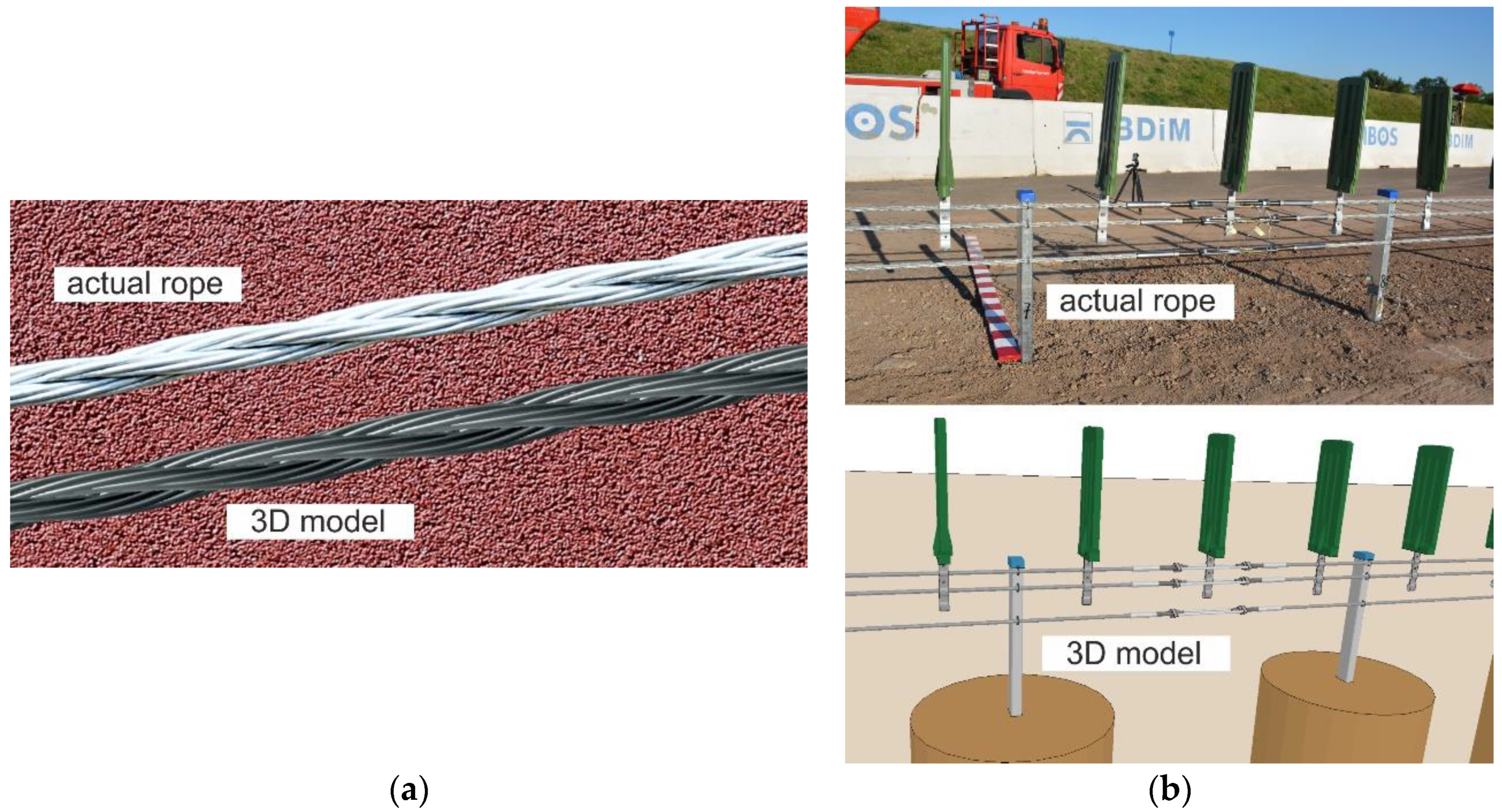
As shown in Figure 2(a), the WRI was composed of two pallets and twelve 6 × 19 IWS wire ropes. In this paper, the simplified finite element method is used to obtain the WRI load-displacement hysteresis loop, and the WRI stiffness damping of different structural parameters is discussed. We have referenced the simplified finite element method which was established by Cen et al. [24]. This method mainly simplified the single strand into a single wire. The 6 × 19 IWS wire rope was simplified into the 1 × 7 wire rope, as presented in Figure 2(b). Based on the simplified method, this paper studies the stiffness and damping characteristics of the isolators with different structural parameters and establishes the prediction model of the stiffness damping of the wire rope isolator with structural parameters as variables.
This paper is mainly based on the GGQ-99 Polycal WRI. By changing structural parameters, the diameter ratio and lay pitch of the single strand and lay pitch and bending radius of the wire rope, different finite element models were set.
In this presented model, the data source of the simulation of the WRIs refers to papers of Cen et al. [24], Jiang et al. [25], and Erdonmez and Imrak [26]. The material properties of the center and side wires are defined by the bilinear elastic-plastic kinematic hardening model in the ABAQUS material library, as shown in Table 1. By compression of corresponding strands, the max equivalent compression stress of the strand and equivalent compression elastic modulus are equal to and Ep, respectively. Ee is equal to the equivalent tension elastic modulus which is measured by the tension of the strands. The density is ρ = 7850 kg·m−3, and the Poisson’s ratio is μ = 0.3 [24].
The stiffness of the WRI determines the load-bearing capacity of the vibration isolation system, regardless of whether the WRI is subjected to a static load or a strong impact load. The softening load of the WRI and the subsequent softening stiffness both affect the efficiency of vibration isolation and stability of the entire isolator system. The damping characteristic reflects the ability to absorb shock vibration energy of the isolator in the vibration isolation system. There are many factors that affect the static stiffness and damping characteristics of the WRI, including the selection of the wire rope, number of wire ropes, material of steel wire, wire rope diameter (D), rope lay pitch (), single wire rope diameter (d), single wire strand lay pitch (), wire rope diameter ratio (nr), and arc wire rope bending radius (R).
As shown in Figure 3, the diameter ratio (nr) of the 1 + 6 + 12 center strand or the lay strand is defined as follows:where rc and rs are the diameters of the center wire and lay wire in the single strand, respectively.
Figure 3 shows the 1 + 6 + 12 single-strand wire rope. It was stipulated that the 1 + 6 + 12 single-strand wire rope has the same other structural parameters; the first layer wire pitch length was 6 times the diameter of the single wire rope, and the second layer wire pitch length was 11 times the diameter of the single wire rope. The diameter of the wire rope was 8 mm in the study of the GGQ-99 Polycal WRI. The diameter of the center strand was 2.839 mm, and the diameter of the lay strand was 2.581 mm. Obviously, the former was 1.1 times more than the latter. The lay pitch length was 60 mm (7.5 times diameter of the wire rope), and the bending radius was 46.5 mm of the arc wire rope. The diameters of the center wire and lay wire in different strands with different diameter ratios of the GGQ-99 are listed in Table 2.
According to the simplified FEM model, the tensile and compression of the single strand with different diameter ratios were calculated. The elastic tensile and compression modulus and compression ultimate load of the single strand were obtained. These mechanical parameters were used to calculate the stiffness-damping characteristics of the WRI. It is presented in Table 3. It could be seen that the elastic tensile modulus significantly reduced with increased diameter ratio. But the elastic compression modulus increased with increased diameter ratio. The compression ultimate load is kept steady basically with increased diameter ratio. The reason is that the compression ultimate load indicated the friction properties between the center wire and lay wire. The friction between the center wire and lay wire was retained about the same during calculating the model with different diameter ratios. So, the compression ultimate loads showed little changes.
According to the simplified FEM model, the compression loading-unloading processes of the GGQ-99 WRI with different diameter ratios were simulated. Different load-displacement hysteresis loop curves of the WRI are shown in Figure 4. The ratio between the prestiffness K1 and softened stage stiffness K2 indicated the impact resistance for the WRI. The smaller this value, the better the impact resistance. The energy dissipation coefficient was used to evaluate the damping characteristic. The higher this value, the better the damping characteristic. The results are shown in Figure 5.
As shown in Figure 4, the compression load of the WRI increased with increasing of the diameter ratio of the wire strand. This result is related to the elastic compression modulus of the single strand. As shown in Figure 5, the ratio of K1 to K2 was increased with increasing of the diameter ratio of the wire strand. The ratio of K1 to K2 reached the minimum when the diameter ratio was equaled to 1.1. It means that the GGQ-99 WRI was easier to maintain the stability of the vibration isolation system through large deformation. The energy dissipation coefficient for the WRI decreased with increasing of the diameter ratio of the wire strand. When the ratio of the strand was equaled to 1.1, the energy dissipation coefficient reached maximum. These results indicate that the Polycal WRI has better damping characteristics, which could effectively consume the impact load and eliminate the vibration from the isolation system.
Based on the diameter ratio of the wire strand to 1.1, the main purpose of this section is to study the effect of the outer layer side wire pitch length () on the stiffness-damping of the Polycal WRI. During the process of creating the simulation model, the first layer side wire of the strand steel wire rope () was unchanged and equal to 6 times the diameter of the wire strand. The was 7 times, 8 times, 9 times, 10 times, and 11 times the diameter of the wire strand. The relation between the pitch length and diameter of the wire strand (d) is expressed in equation (3). The geometric dimensions of the single wire strands with different pitch lengths are shown in Table 4.
As shown in Table 5, the equipment tensile modulus, compression modulus, and softened stress of the wire strands with different were obtained by axial tension and compression. The modulus of the tension was continuously increased with increasing of the outer layer side wire pitch. The modulus of the compression had a small variation with increasing of the outer layer side wire pitch basically, and the maximum load of the corresponding compression process decreased.
The equipment tensile and compression performance of wire strands with different were used to define the bilinear elastic-plastic kinematic hardening material properties of the center and lay strand assembled in the GGQ-99 WRI. As shown in Figure 6, the load-displacement hysteresis loops of different lay pitches had a small variation. Besides, the modulus of the compression was not changing with increasing of the outer layer side wire pitch. Combined stiffness-damping characteristics of the GGQ-99 WRI with the different wire strand pout are shown in Figure 7. When the was 11 times the diameter of the wire strand, the ratio of K1 to K2 reached the minimum. At the same time, the Polycal WRI had large prestiffness and the most obvious softening characteristics, not only could withstand large loads but also could easily maintain the stability of the vibration isolation system through large deformation under the action of large loads. The energy dissipation coefficient of the WRI remained basically unchanged, when the ratio of the outside lay pitch and the diameter of the strand increased.
In the process of compression loading-unloading of the Polycal WRI, not only the slippage of the wires exists in the strand but also the overall slippage of the strands in the rope. Therefore, the influence rule of the pitch length on the wire rope is discussed in this section. The diameter ratio, the inside layer wire pitch length and outside layer wire pitch, was equaled to 1.1. It was 6 times the diameter of the wire strand and 11 times the diameter of the wire strand, respectively. The relation between the pitch length and diameter of the wire rope (D) is expressed in equation (4). Table 5 lists the geometric dimensions of the single wire strands with different pitch lengths. The load-displacement hysteresis loops of the GGQ-99 WRI with different pitch lengths are shown in Figure 8.
As shown in Figure 8, the compression load of the WRI increased with increasing of the pitch length of the wire rope. The increase of the pitch length contributed to the increase of the angle between the center strand and lay strand. The bearing axial load of the lay strand increased with angle between center strand and lay strand decreasing. So, the compression load of the WRI was increased with the increasing of the pitch length of the wire rope.
The stiffness-damping characteristics of the GGQ-99 WRI with different pitch lengths of wire ropes are shown in Figure 9. As shown in Figure 9, both the ratio of K1 to K2 and the energy dissipation coefficient of the WRI fluctuated with the increase of the pitch length of the arc rope. When the rope pitch was equaled to 7.5 times the diameter of rope, the ratio of K1 to K2 was the smallest and less than 0.2 and the energy dissipation coefficient was the biggest.
The characteristics of the Polycal WRI depend on the structure of the wire rope, including the diameter of the single strand, the pitch length of the single strand, and the bending radius of the wire rope. In this section, the influence of the bending radius (R) of the arc rope on the stiffness-damping characteristics of the Polycal WRI is studied. The diameter ratio of the wire strand was 1.1. The inside layer wire pitch length was 6 times the diameter of the wire strand. The outside layer wire pitch length was 11 times the diameter of the wire strand, and the pitch length of the wire rope was 7.5 times its diameter. The bending radius was equal to 46.5 mm, and the bending radius of the wire rope was 50 mm, 55 mm, 60 mm, and 65 mm, respectively. The FEM models of the GGQ-99 WRI with different bending radii are shown in Figure 10. The load-displacement hysteresis loops of the GGQ-99 WRI with different bending radii of arc ropes are shown in Figure 11.
As shown in Figure 11, the compression load of the WRI increased with increasing bending radius of arc ropes. Because the compression load of the WRI was inversely proportional to the curvature of the wire rope, the curvature of the wire rope decreased with increasing bending radius of arc ropes. The compression load of the WRI increased with increasing bending radius of arc ropes.
The stiffness-damping characteristics of the GGQ-99 WRI with different bending radii of the wire rope are shown in Figure 12. The ratio of K1 to K2 increased with increasing bending radius. However, the energy dissipation coefficient of the WRI decreased with increasing bending. When the bending radius was equal to 46.5 mm, the ratio of K1 to K2 was the smallest and the energy dissipation coefficient was the biggest.
In conclusion, the stiffness-damping characteristics were the best; when the diameter ratio of the wire strand was 1.1, the inside layer wire pitch length was 6 times the diameter of the wire strand, the outside layer wire pitch length was 11 times the diameter of the wire strand, and the pitch length of the wire rope was 7.5 times its diameter. The bending radius was equal to 46.5 mm.
In the previous section, the influence rules of the diameter ratio of the wire strand (nr), the pitch length of the wire strand (), the pitch length of the wire rope (P), and the bending radius (R) for the stiffness-damping performance of the Polycal WRI were discussed. The prediction model of the stiffness-damping characteristic of the WRI was established by using the dimensionless diameter ratio of the wire strand (nr), the pitch length of the wire strand (), the pitch length of the wire rope (P), and the bending radius (R). The theoretical basis of equations (5) and (6) is the theorem in dimensional analysis. According to the principle of dimensional analysis, all structural parameters are transformed into a dimensionless form, and the number of variables is reduced to obtain the corresponding calculation formula as follows:where E1 is the elastic modulus of the steel wire material (E1 = 193000 MPa), H is the height of the GGQ-99 WRI (H = 99 mm), and D is the diameter of the arc rope (D = 8 mm). The x, k, and c are the undetermined coefficients in the stiffness and damping models, respectively.
As shown in Table 6, all values of the prestiffness K1, softened stiffness K2, and energy dissipation coefficient C of the GGQ-99 Polycal WRI with different structural parameters were obtained. The coefficient values are listed in Table 7. By using the MATLAB software, equations (5) and (6) were formulated fitting with the corresponding structural parameters, respectively.
As shown in Table 8, the errors of the prestiffness and softened stiffness fitting formulas of the WRI were all within 10%, and more than half of the errors were within 5%. The error of the energy dissipation coefficient of the WRI with the formula was basically within 20%, and more than half of the errors were within 10%. It could be considered that the formula fitted in this study is accurate and reliable by analysing the error results of the overall data. In the design of the Polycal WRI, the stiffness-damping characteristics could be quickly obtained.
The wire rope structural parameters of the GGQ25-62 Polycal WRI are given in Table 9. Besides, the values of H, D, and R are 62 mm, 4.68 mm, and 27.15 mm, respectively.
Through the out-of-plane compression loading-unloading experiment of the WRI, its stiffness-damping characteristics were obtained. Figure 13 shows the load-displacement curve of the GGQ25-62WRI, and the values of K1, K2, and C could be calculated from this figure, and Table 10 also shows the specific values.
The fitted value was compared with experimental data. As shown in Table 11, the errors of the prestiffness and softened stiffness fitting formulas of the WRI the values were all within 20%. The reason for this phenomenon is that the finite element is an analysis under ideal conditions. During the test, the vibration isolator is in a complex state, and there will be some nonlinearity characteristics. Therefore, it can be seen that the predicted value given by the prediction model is in good agreement with the experimental value.
This paper firstly presented the results of the mechanical properties of the wire rope with different diameter ratios and lay pitches of the single strand. By using the corrected simplified finite element method of the Polycal WRI, the influence of the diameter ratio and lay pitch of the single strand and the lay pitch and bending radius of the wire rope on the stiffness and damping characteristics of the Polycal WRI were studied. Several key conclusions are summarized as follows:(1)The stiffness-damping characteristics were best; when the diameter ratio of wire strand was 1.1, the inside layer wire pitch length was 6 times the diameter of the wire strand, the outside layer wire pitch length was 11 times the diameter of the wire strand, the pitch length of the wire rope was 7.5 times its diameter, and the bending radius was equal to 46.5 mm.(2)The effective prediction models of stiffness and damping about the structural parameters of the wire rope were established, which combined the properties of a steel wire material and the overall structure of the WRI. More than half of the errors of the prestiffness and softened stiffness fitting formulas of the Polycal WRI were within 5%. And more than half of the errors of the energy dissipation coefficient of the WRI were within 10%. The fitted value was compared with the experimental data, the errors were within 20%, and the prediction model was verified.

Wire rope and cable are each considered a “machine”. The configuration and method of manufacture combined with the proper selection of material when designed for a specific purpose enables a wire rope or cable to transmit forces, motion and energy in some predetermined manner and to some desired end.
Two or more wires concentrically laid around a center wire is called a strand. It may consist of one or more layers. Typically, the number of wires in a strand is 7, 19 or 37. A group of strands laid around a core would be called a cable or wire rope. In terms of product designation, 7 strands with 19 wires in each strand would be a 7×19 cable: 7 strands with 7 wires in each strand would be a 7×7 cable.
Materials Different applications for wire rope present varying demands for strength, abrasion and corrosion resistance. In order to meet these requirements, wire rope is produced in a number of different materials.
Stainless Steel This is used where corrosion is a prime factor and the cost increase warrants its use. The 18% chromium, 8% nickel alloy known as type 302 is the most common grade accepted due to both corrosion resistance and high strength. Other types frequently used in wire rope are 304, 305, 316 and 321, each having its specific advantage over the other. Type 305 is used where non-magnetic properties are required, however, there is a slight loss of strength.
Galvanized Carbon Steel This is used where strength is a prime factor and corrosion resistance is not great enough to require the use of stainless steel. The lower cost is usually a consideration in the selection of galvanized carbon steel. Wires used in these wire ropes are individually coated with a layer of zinc which offers a good measure of protection from corrosive elements.
Cable Construction The greater the number of wires in a strand or cable of a given diameter, the more flexibility it has. A 1×7 or a 1×19 strand, having 7 and 19 wires respectively, is used principally as a fixed member, as a straight linkage, or where flexing is minimal.
Selecting Wire Rope When selecting a wire rope to give the best service, there are four requirements which should be given consideration. A proper choice is made by correctly estimating the relative importance of these requirements and selecting a rope which has the qualities best suited to withstand the effects of continued use. The rope should possess:Strength sufficient to take care of the maximum load that may be applied, with a proper safety factor.
Strength Wire rope in service is subjected to several kinds of stresses. The stresses most frequently encountered are direct tension, stress due to acceleration, stress due to sudden or shock loads, stress due to bending, and stress resulting from several forces acting at one time. For the most part, these stresses can be converted into terms of simple tension, and a rope of approximately the correct strength can be chosen. As the strength of a wire rope is determined by its, size, grade and construction, these three factors should be considered.
Safety Factors The safety factor is the ratio of the strength of the rope to the working load. A wire rope with a strength of 10,000 pounds and a total working load of 2,000 pounds would be operating with a safety factor of five.
It is not possible to set safety factors for the various types of wire rope using equipment, as this factor can vary with conditions on individual units of equipment.
The proper safety factor depends not only on the loads applied, but also on the speed of operation, shock load applied, the type of fittings used for securing the rope ends, the acceleration and deceleration, the length of rope, the number, size and location of sheaves and drums, the factors causing abrasion and corrosion and the facilities for inspection.
Fatigue Fatigue failure of the wires in a wire rope is the result of the propagation of small cracks under repeated applications of bending loads. It occurs when ropes operate over comparatively small sheaves or drums. The repeated bending of the individual wires, as the rope bends when passing over the sheaves or drums, and the straightening of the individual wires, as the rope leaves the sheaves or drums, causing fatigue. The effect of fatigue on wires is illustrated by bending a wire repeatedly back and forth until it breaks.
The best means of preventing early fatigue of wire ropes is to use sheaves and drums of adequate size. To increase the resistance to fatigue, a rope of more flexible construction should be used, as increased flexibility is secured through the use of smaller wires.
Abrasive Wear The ability of a wire rope to withstand abrasion is determined by the size, the carbon and manganese content, the heat treatment of the outer wires and the construction of the rope. The larger outer wires of the less flexible constructions are better able to withstand abrasion than the finer outer wires of the more flexible ropes. The higher carbon and manganese content and the heat treatment used in producing wire for the stronger ropes, make the higher grade ropes better able to withstand abrasive wear than the lower grade ropes.
Effects of Bending All wire ropes, except stationary ropes used as guys or supports, are subjected to bending around sheaves or drums. The service obtained from wire ropes is, to a large extent, dependent upon the proper choice and location of the sheaves and drums about which it operates.
A wire rope may be considered a machine in which the individual elements (wires and strands) slide upon each other when the rope is bent. Therefore, as a prerequisite to the satisfactory operation of wire rope over sheaves and drums, the rope must be properly lubricated.
Loss of strength due to bending is caused by the inability of the individual strands and wires to adjust themselves to their changed position when the rope is bent. Tests made by the National Institute of Standards and Technology show that the rope strength decreases in a marked degree as the sheave diameter grows smaller with respect to the diameter of the rope. The loss of strength due to bending wire ropes over the sheaves found in common use will not exceed 6% and will usually be about 4%.
The bending of a wire rope is accompanied by readjustment in the positions of the strands and wires and results in actual bending of the wires. Repetitive flexing of the wires develops bending loads which, even though well within the elastic limit of the wires, set up points of stress concentration.
The fatigue effect of bending appears in the form of small cracks in the wires at these over-stressed foci. These cracks propagate under repeated stress cycles, until the remaining sound metal is inadequate to withstand the bending load. This results in broken wires showing no apparent contraction of cross section.
Experience has established the fact that from the service view-point, a very definite relationship exists between the size of the individual outer wires of a wire rope and the size of the sheave or drum about which it operates. Sheaves and drums smaller than 200 times the diameter of the outer wires will cause permanent set in a heavily loaded rope. Good practice requires the use of sheaves and drums with diameters 800 times the diameter of the outer wires in the rope for heavily loaded fast-moving ropes.
It is impossible to give a definite minimum size of sheave or drum about which a wire rope will operate with satisfactory results, because of the other factors affecting the useful life of the rope. If the loads are light or the speed slow, smaller sheaves and drums can be used without causing early fatigue of the wires than if the loads are heavy or the speed is fast. Reverse bends, where a rope is bent in one direction and then in the opposite direction, cause excessive fatigue and should be avoided whenever possible. When a reverse bend is necessary larger sheaves are required than would be the case if the rope were bent in one direction only.
Stretch of Wire Rope The stretch of a wire rope under load is the result of two components: the structural stretch and the elastic stretch. Structural stretch of wire rope is caused by the lengthening of the rope lay, compression of the core and adjustment of the wires and strands to the load placed upon the wire rope. The elastic stretch is caused by elongation of the wires.
The structural stretch varies with the size of core, the lengths of lays and the construction of the rope. This stretch also varies with the loads imposed and the amount of bending to which the rope is subjected. For estimating this stretch the value of one-half percent, or .005 times the length of the rope under load, gives an approximate figure. If loads are light, one-quarter percent or .0025 times the rope length may be used. With heavy loads, this stretch may approach one percent, or .01 times the rope length.
The elastic stretch of a wire rope is directly proportional to the load and the length of rope under load, and inversely proportional to the metallic area and modulus of elasticity. This applies only to loads that do not exceed the elastic limit of a wire rope. The elastic limit of stainless steel wire rope is approximately 60% of its breaking strength and for galvanized ropes it is approximately 50%.
Preformed Wire Ropes Preformed ropes differ from the standard, or non-preformed ropes, in that the individual wires in the strands and the strands in the rope are preformed, or pre-shaped to their proper shape before they are assembled in the finished rope.
This, in turn, results in preformed wire ropes having the following characteristics:They can be cut without the seizings necessary to retain the rope structure of non-preformed ropes.
They are substantially free from liveliness and twisting tendencies. This makes installation and handling easier, and lessens the likelihood of damage to the rope from kinking or fouling. Preforming permits the more general use of Lang lay and wire core constructions.
Removal of internal stresses increase resistance to fatigue from bending. This results in increased service where ability to withstand bending is the important requirement. It also permits the use of ropes with larger outer wires, when increased wear resistance is desired.
Outer wires will wear thinner before breaking, and broken wire ends will not protrude from the rope to injure worker’s hands, to nick and distort adjacent wires, or to wear sheaves and drums. Because of the fact that broken wire ends do not porcupine, they are not as noticeable as they are in non-preformed ropes. This necessitates the use of greater care when inspecting worn preformed ropes, to determine their true condition.


 8613371530291