
wire rope bolt free sample
Lexco® Cable offers a large selection of wire rope and aircraft cable hardware and tools. Our hardware items are made for attaching cable and wire rope to structures, supports, and other cables and wire ropes. Unlike our cable fittings, this hardware is not crimped or swaged to the wire rope or cable but is attached through other means, generally through an eyehole on the hardware itself. Our tools are designed to make working with and attaching aircraft cable, wire rope, and hardware faster, easier, and safer.
All of our aircraft cable and wire rope hardware is available in bulk quantities or as part of a complete cable assembly. We specialize in cable assembly fabrication to save you time and money in additional production costs.
Request a quote for the aircraft cable or wire rope hardware items or tools you need, or contact Lexco® for more information. If you cannot find the hardware items or tools that you need in our online inventory, please contact your Lexco® Cable sales representative. We’ll be happy to help you find the ideal product for your application.
Wire rope is an extremely versatile mechanical device that can be used to help support and move an object or load. Whether for use on cranes or for other lifting applications, it’s important to have a solid understanding of the rigging components that are being used to attach to and lift a load.
As a rigger or end-user of wire rope, it’s necessary to understand the types of wire rope end termination, or treatments that can be used at the ends of a length of wire rope—one of the most common being wire rope clips.
Wire rope clips can be used to form a load bearing eye at the end of a cable or wire rope, or to connect two cables together with a lap splice. Wire rope clips are popular because they can be installed in the field and provide 80-90% efficiency of the rope breaking strength, depending on the diameter of the wire rope.
As a general guideline, they are NOT to be used for making slings, as ASME B30.9 Slingsstandard states: “Mechanical wire rope terminations requiring periodic adjustment to maintain efficiency shall not be used to fabricate slings.”
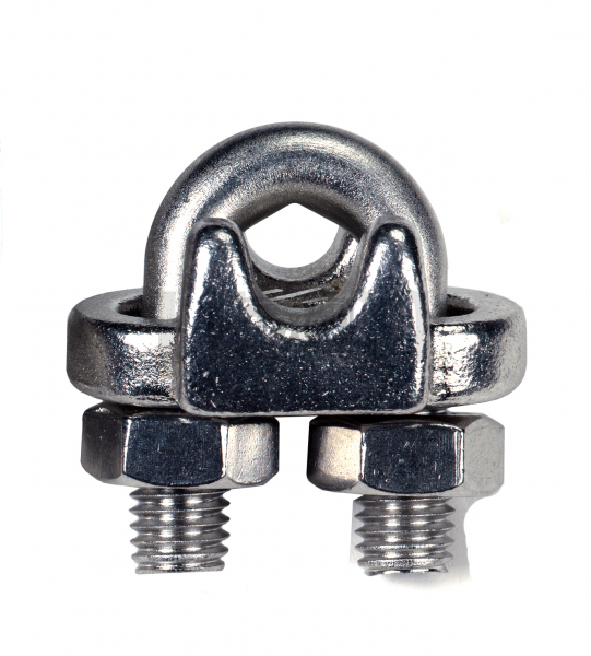
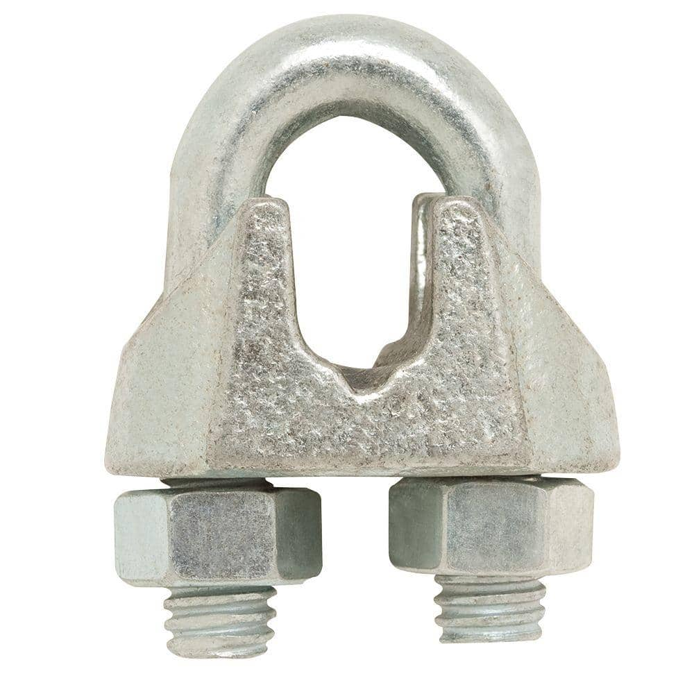
There are two main types of wire rope clips—U-Bolt and double saddle clips. U-Bolt wire rope clips are the most common and may be made of forged or malleable metal.
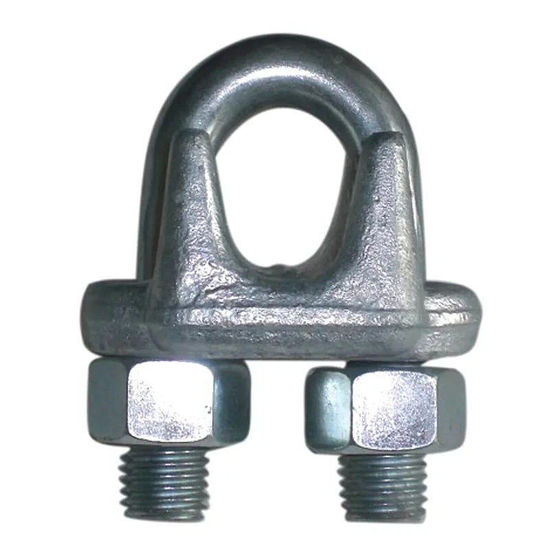
This type of wire rope clip is essentially a U-bolt, two nuts, and a metal base (saddle) that can be made from forged steel or cast iron. Careful consideration and attention must be given to the way U-bolt type wire rope clips are installed.
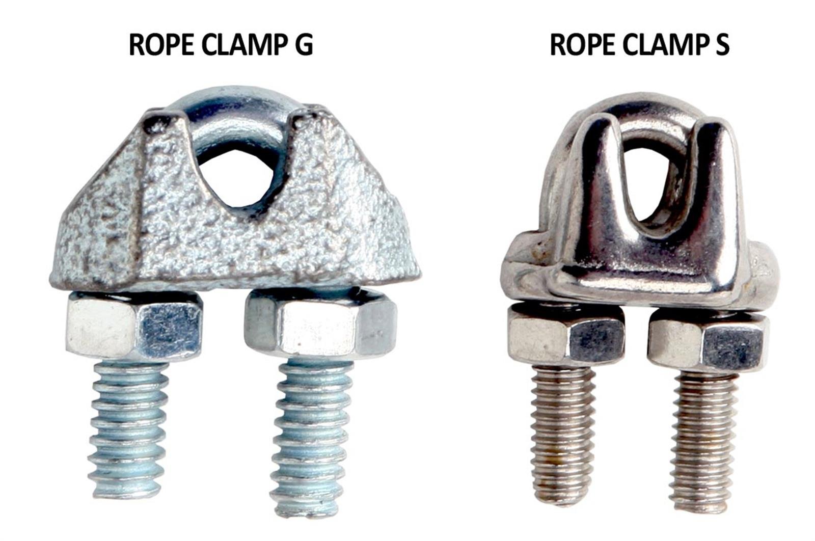
The base of the wire rope clip is made from forged steel. Forged clips are heated and hammered into the desired shape—resulting in a consistent grain structure in the steel. Forged wire rope clips are used for critical, heavy-duty, overhead loads such as winch lines, crane hoist lines, support lines, guy lines, towing lines, tie downs, scaffolds, etc.
Malleable wire rope clips are used for making eye termination assemblies only with right regular lay wire rope and only for light duty uses with small applied loads, such as hand rails, fencing, guard rails, etc. The base of the wire rope clips is made from malleable cast iron, which may fracture under heavy use and does not have the desirable metal properties of steel, or the beneficial grain structure that a forged base has.
Unfortunately, it is not uncommon to see a wire rope clip applied incorrectly. Some of the most common mistakes include:Not torquing to the manufacturer’s expectations
Wire rope clips require the use of a torque wrench in order to function properly. Torquing the nuts on the clips too much or too little can cause the clip to fail. If the clip is over-torqued, it could damage the threads of the wire rope. If the clip is under-torqued, the holding power of the clip is diminished and the wire rope could slip through.
There are a minimum number of clips required for use related to the wire rope diameter. Using less than the number of specified clips could result in decreased efficiency and possible failure.
Depending on the number and size of the wire rope clips, there is a proportional amount of space required between the placement on each clip on the rope.
There are two sides of a U-Bolt style wire rope clip: the saddle and the U-Bolt. When securing a wire rope eye, it is important to place the clip on the correct end of the rope.
A saying commonly used in rigging to help remember this is: “Never saddle a dead horse!” In other words, never put the saddle on the dead end of the rope.
The turnback is the portion of the wire rope eye that runs from the end of the bearing eye to the live end. Having less than the suggested amount of turnback will decrease the efficiency of the wire rope eye and could lead to failure.
It is important to be sure you are using the correct wire rope clip—forged or malleable wire rope clips—for the application. Malleable clips can only be used for non-critical uses, such as tension rope to form a perimeter around a parking lot.
If the use is critical—an application where, if there is a failure, you have potential injury or loss of life or damage to property—a forged clip must be used.
The clip size used—whether it be 1/8”, 3”, or otherwise—must match the diameter size of the wire rope. If it doesn’t, the wire rope could slip out of the clip.
After installing clips, it is necessary to regularly cycle the rope and retighten the clips. Monitoring the torque on the nuts is important, as they will loosen over repeated use.
Basic steps for installing a wire rope clip include:First, wrap the wire rope around the thimble or to form the eye, and turn back the correct amount of rope—as specified by the manufacturer.
Apply the first wire rope clip at the end of the dead end, with one base width of space. Use a torque wrench to tighten the nuts on the wire rope clip.
When applying the second clip (if required), place it as close to the eye loop or thimble as possible. Again, be sure to properly tighten the nuts of the clip with a torque wrench.
Wire rope clips are a common and necessary piece of rigging hardware when it comes to using wire rope and forming end terminations. They are used to form a wire rope eye or to connect two cables together. It’s important to understand how to correctly install a wire rope clip, as incorrect installation leads to decreased efficiency in the wire rope assembly.
The mining industry has used a number of artificial means of support. Devices such as patch plates, structural steel channels, rock bolts, and wire ropes have been used to strengthen the backs, roofs, and pillars in many mines. Wire rope was used on some pillars in the lead mines in the Tri-State area. However, there has been no experimental work performed to quantitatively predict or determine the strength increase resulting from the use of rock bolts or wire rope on pillars containing a plane of weakness,
The purpose of these investigations is to quantitatively determine the increase in strength resulting from the use of rock bolts and wire rope on model pillars containing a plane or parallel planes of weakness oriented at various angles from the vertical axis of the core. From these investigations, equations have been developed to predict this increase in strength based upon the Coulomb failure criterion.
The effect of installing rock bolts normal to the plane of weakness in a cylindrical pillar (fig. 1c) is to increase the shear resistance along the plane of weakness by the shear strength of the bolts, provided that the bolt is tight in the hole. The effect of tensioning the rock bolts is to increase the normal load on the plane of weakness, and this in turn increases the friction effect. We therefore postulate that a determination of the average shear stress and normal stress along and across the plane of weakness, respectively, is sufficient for a first-order approximation to calculate the increase of shear resistance due to the rock bolts. Thus, to calculate the increase of shear resistance, we need to know only the number of bolts (N) , the tensile stress in the bolts (Tb), the shear strength of the bolts (Sb), and the ratio of the cross-sectional area of the bolts to the area of the weakness plane (Ab/Af). Equation 1 is rewritten in the form
The effect of wrapping pretensioned wire ropes on the surface of a model rock pillar (fig. 1d) is analogous to applying an effective confining pressure over the pillar surface. This analogy is rigorously true when the number of ropes per unit length becomes very large.
For ease of calculation, the wire rope is approximated as a thick-walled cylinder having a square cross-sectional area and subject to an internal pressure of magnitude Pi. The tangential stress (σθ) at a fixed radial distance (r) in the thick-walled cylinder is determined as follows:
where a and b’ are the inner and outer radii of the wire cylinder, respectively, and a≤r≤b’. Note that a is also the radius of the model pillar. The total tangential force (T’) acting on a wire rope of thickness t is found from equation 13 to be
The total force generated by N wire ropes of thickness t is 2πNatPi, which must equal the total force (2π aLσ3) resulting from an average stress σ3 applied to the cylindrical surface, where L is the pillar length. Thus from equation 14 we find that
Experiments were conducted on NX cores (2.125-in diameter) with an L/D (length/diameter) value of 2.47. Six different rock types were used for this study. Standard uniaxial compression-testing procedures were used on some wire-roped specimens with the plane of weakness at a noncritical β angle (>60°). For the majority of the samples with the plane of weakness at a critical β orientation, end platens had to be glued to the rock-bolted and wire-roped specimens to afford end constraint. This end-constraint technique was used previously and was necessary in order to test those specimens.
In the rock-bolt testing phase of this study, natural fractures oriented at an angle of approximately 45° to the long axis of the pillar were created for the sandstone, marble and Indiana limestone. Rock-bolt holes were drilled using a small diamond bit normally used in lapidary work. Diamond-saw-cut fracture planes were made for the oil shale, since natural fractures at any angle to the kerogen layers were difficult to generate for this rock.
For the wire-rope testing phase, the cut surfaces of Texas limestone, Longmont sandstone, and Salida granite were surface-finished with a grinder. The ground, saw-cut surfaces were used to simulate the weakness plane for the rock samples. Saw-cut surfaces were used for these rock types because considerable data were available from a previous study. Samples were also prepared containing wafers of various T/D (thickness to diameter) values as described in an earlier paper.
Steel drill rod with a 1/16-in diameter, threaded at both ends with a No. 0-80 machine screw, was used to simulate the rock bolt. Five rock bolts per specimen were used and secured at both ends by steel nuts and brass washers (1/16 in thick by 3/8 in diameter). The brass washers were used to minimize the friction between the nut and the bearing plate and to give a truer value of the torque applied. The average tensile breaking force of
the miniature rock bolts was found to be 150 pounds as determined by the Dillon force gage shown in figure 2. Thus the tensile strength is 49,000 psi based on a bolt cross-sectional area of 0.00306 in². A tension load of 80 pounds per bolt was applied by means of a precision torque wrench as shown in figure 3. The average shear strength of the miniature rock bolts as determined by laboratory tests was 100,000 psi.
Piano wire with a 0.033-in diameter was used to simulate the wire rope. The average tensile breaking force of this simulated wire rope was 272 pounds.
Equation 17 shows that for wire roping to have a significant effect on the strength of pillars, the quantity T’N/DLSf [sin 2β + µf (1 + cos 2β)] should
be as large as practical, so that the normalized ratio Cf”/Cf will be large. The maximum value of the expression in the brackets occurs when cot 2β = µf. Thus wire roping is most effective for critically oriented planes of weakness. For T’N/DLSf to be large, the tensile force in the rope and the number of ropes should be as large as practical. Therefore for the model pillars it was decided to make T’ = 100 lb and N = 10. This force (T’ = 100 lb) was pretensioned in the wires by means of modifying the Dillon force gage. Thus for a pillar 5.25 in long, the spacing Δo of the ropes is ½ in.
Figure 5 shows wire-roped limestone specimens with saw-cuts at (3 angle values ranging from 30° to 60° and T/D (thickness to diameter) values from 0 to 1.
Some physical properties of the fractured model pillars are necessary in order to solve the equations given in the theory. Table 1 gives the values of Sf, µf , and Co of the rock types tested, where Co is the uniaxial compressive strength of the solid cores. Salida granite values of Sf and µf are not available because of the difficulty in testing these cores with a plane of weakness oriented at 45°.
A total of approximately 81 bolted and unbolted samples of 4 rock types were tested. Table 2 shows the theoretical and measured values of the strength increase for 5 rock bolts tensioned across the plane of weakness. The theoretical strength increase was calculated from equation 12. This value differs from the measured values by the following amounts: 58 pct for the sandstone, 13 pct for the marble, 2 pct for the limestone, and 6 pct for the oil shale. The comparison of the theoretical and measured values is good in view of the fact that a natural variability of 10 to 15 pct is inherent for the strength determinations for the rock samples without rock bolts. What is more important than the comparison of the theoretical and measured values is the fact that a significant increase in strength can be effected by the use of rock bolts.
Figure 6 illustrates two examples of bolted specimens with natural breaks, with both specimens taken to failure. The mode of failure in each specimen indicates that major cracks form first along the weakness plane in a direction normal to that plane. As the cracks grow, their direction gradually approaches parallelism with the maximum principal applied stress. A rock-bolted oil shale specimen with a saw-cut at 45° to the applied stress axis taken to failure is shown in figure 7. Again, the predominant crack growth direction is parallel to the applied stress axis.
An additional series of tests was performed to assess the effectiveness of rock bolts attached at an angle other than normal to the fracture surface. These tests were performed on the marble and sandstone with some bolts oriented at angles as much as 20° from the normal to the plane of weakness. The results of these tests indicated that the orientation of the bolts from 0° to 20° from the normal to the plane of weakness had no significant effect upon the strength of the bolted pillar.
Approximately 200 wire-roped samples of Texas limestone, Longmont sandstone, and Salida granite were tested. Table 3 shows the results of the tests with each value in the table representing an average of at least 5 tests. These results show that in general the most benefit from wire roping
is obtained when the planes of weakness are nearly critically oriented (about 33°). The few exceptions in table 3 are within the limits of natural rock variability. Two other conclusions can be drawn from the results of table 3: (1) The weakest rock, limestone, exhibits the largest strength increase due to wire roping; and (2) in all instances, wire roping is effective in increasing the rock strength.
It is well documented that the compressive strength of rocks increases with confining pressure. Variation of the compressive strength with confining pressure of two of the rock types tested is plotted in figure 8 and the values are given in table 4 together with the standard deviation. If equation 15 is used with N = 10 and T’ = 100 pounds, the wires produce an effective confining pressure (σ3) of 179 psi. The lateral pressure of 179 psi, as shown on figure 8, produces strength values of 9,600 and 26,700 psi for the limestone and sandstone, respectively. These values are 9 and 8 pct greater than the Co values of limestone and sandstone, respectively. These increases were verified by experimental testing, but again fall into the 10- to 15-pct range of natural rock variability. However, as a first-order approximation, equation 15 would appear valid and correct.
To check the validity of equation 16 to predict the strength due to wire roping of pillars of rock containing a plane of weakness, a few of the values of table 4 were compared to the theoretical strength as determined by equation 16 and are listed in table 5. T/D values as close to 0 as possible were chosen, since the theory was developed with a single plane of weakness, or T/D = 0. These results indicate a maximum error of 24.4 pct for the sandstone with a β angle of 40° and a 19.2-pct error for the limestone with a β angle of 45°. Therefore, as a first-order approximation of the strength, equation 16 would appear valid and correct. All other comparisons of the theoretical strength against the laboratory determined strength are excellent; error values range from 0.0 to 8.6 pct.
A finite element analysis of the wire-rope experiments was performed to check the validity of the value of the effective confining pressure approximation brought about by the wire roping. Figure 9 illustrates the specimen-wire rope-end plate geometry and the coordinate system nomenclature used in this analysis. The length and diameter of the specimen are denoted by L (L = 2b, b is the half-length of the specimen) and D (D = 2a, a is the specimen radius), respectively. The distance between successive wire ropes is denoted by Δo. A constant displacement of magnitude δo is applied to the end plates to approximate the conditions existing in laboratory studies of a specimen loaded between rough steel end plates.
The three-dimensional, axisymmetric, finite element method of solution was used to determine the effective confining pressure in a cylindrical specimen with an L/D value of 2.50, wrapped with steel wire ropes pretensioned to a 100-lb force. The whole system was compressed uniaxially between rough steel end plates of L/D value equal to 0.25. Figure 10 shows the finite element idealization of the problem. The Young’s modulus and Poisson’s ratio for the specimen were chosen as 5 x 10 6 psi and 0.24, respectively; and for the end plate, 30 x 10 6 psi and 0.30. The material properties of the wire
are the same as the end plates. Four different spacing distances between the wire ropes were considered; namely, Δo = ¼ in, Δo = ½ in, Δo =1 in, and no wire ropes (Δo = L). For brevity, only the cases where Δo = ½ in and Δo = L are discussed in detail.
Figures 11 and 12 illustrate the variations of the axial stress (σzz), radial stress (σrr), tangential stress (σθθ), and shear stress (σrz ), with the radial (r/a) and axial (z/b) directions for spacing distances (Δo) between adjacent wires equal to L (no wire ropes on specimen) and ½ in, respectively. The symbol Δ figure 12 represents a distance within any two adjacent wires, that is, 0 ≤ A ≤ Δo.
A detailed discussion of the stress distribution in a test specimen compressed between rough steel end plates with no wire ropes (Δo = L) on the specimen has been published elsewhere. There are only two results of
importance to the present analysis: (1) Nearly 70 pct of the specimen can be considered to be under a uniform state of stress, and (2) the average confining pres-sure in the specimen due to end effects is negligible. The magnitude of this pressure is found by averaging the sum of the radial and tangential stress throughout the entire specimen and dividing the result by two. Figure 12 shows the stress distribution in the specimen in the region between two adjacent wire ropes near the central portions of the specimen (0 ≤ z ≤ 0.50 in). End effects due to the steel end plates are nonexistent at this position. The results of the finite element study showed that there was no increase in stress in the wire ropes due to deforming the test specimen. The location Δ/Δo equal to 0 or 1.00 corresponds to a wire-rope position. The effect of using wire ropes pre-tensioned to a 100-lb force can be seen to result in a somewhat uniform radial and tangential stress distribution within the interior portions of the specimen (0 ≤ r/a ≤ 0.50). The radial and
tangential stresses approach zero at the specimen boundary (r/a = 1.00), except at the wire-rope locations (Δ = 0, Δ = Δo. At the wire-rope locations, both the radial and tangential stresses appear to approach the value 2.53 σ1, where σ1, the stress existing in the specimen when no end effects are present, is equal to 1,120 psi. This value of σ1 is found by averaging the axial stress across the specimen. Table 6 shows the average confining pressure in the specimen for the wire-rope spacings considered in this study. The theoretical values obtained from equation 10 are shown for comparison. The maximum error between the theoretical and finite element average confining pressure value amounts to only 6 pct. This result shows that equation 15 can be used with confidence in estimating the mean confining pressure due to wrap¬ping pretensioned wire ropes around a cylindrical specimen.
The results of this research would indicate that the use of rock bolts and/or pretensioned wire rope can have a significant effect on the compressive strength of model pillars containing a plane of weakness. Equations for the strength increase of the fractured model pillars which were developed using the Coulomb failure condition for both the case of steel rock bolts and pretensioned steel wire ropes give magnitudes of the compressive strength increase in accord with experiment.
The effect of installing tensioned rock bolts normal to the plane of weakness of the model pillar is shown to be equivalent to increasing the shear resistance along the plane of weakness. The strength increase depends upon the shear strength of the rock bolt, the tensile stress in the rock bolt, the ratio of the cross-sectioned area of the bolt to the area of the weakness plane, and the number of bolts installed. Pillars with critically oriented planes of weakness and with the lowest shear strength values show the largest strength increase, for either rock bolting or wire roping. This strength increase is primarily due to the shear strength of the steel bolts which is at least an order of magnitude greater than the shear strength of the rock (Sf).
The effect of wire roping a model pillar is shown to be analogous to applying an effective confining pressure over the specimen surface. The value of the effective confining pressure is dependent upon the tensile force in each wire and the total number of wires.
The ability to obtain a first-order approximation of the increase in strength of pillars containing planes of weakness by the use of roof bolts and/or wire rope enables one to arrive at a more realistic strength value to be used in the stress analysis of a room-and-pillar mining system.

Cheap Cable Clips, Buy Quality Home Improvement Directly from China Suppliers:16mm 9/16" Wire Rope Clip Stainless Steel U Shaped Bolt Cable Clamp Fastener 2pcs Enjoy ✓Free Shipp…

Cheap Cable Clips, Buy Quality Home Improvement Directly from China Suppliers:16mm 9/16" Wire Rope Clip Stainless Steel U Shaped Bolt Cable Clamp Fastener 2pcs Enjoy ✓Free Shipp…

Employers must not use improved plow-steel wire rope and wire-rope slings with loads in excess of the rated capacities (i.e., working load limits) indicated on the sling by permanently affixed and legible identification markings prescribed by the manufacturer.
An eye splice made in any wire rope shall have not less than three full tucks. However, this requirement shall not operate to preclude the use of another form of splice or connection which can be shown to be as efficient and which is not otherwise prohibited.
Wire rope shall not be used if, in any length of eight diameters, the total number of visible broken wires exceeds 10 percent of the total number of wires, or if the rope shows other signs of excessive wear, corrosion, or defect.
Except for eye splices in the ends of wires and for endless rope slings, each wire rope used in hoisting or lowering, or in pulling loads, shall consist of one continuous piece without knot or splice.
Cable laid and 6 × 19 and 6 × 37 slings shall have a minimum clear length of wire rope 10 times the component rope diameter between splices, sleeves or end fittings.
Fiber core wire rope slings of all grades shall be permanently removed from service if they are exposed to temperatures in excess of 200 °F (93.33 °C). When nonfiber core wire rope slings of any grade are used at temperatures above 400 °F (204.44 °C) or below minus 60 °F (15.55 °C), recommendations of the sling manufacturer regarding use at that temperature shall be followed.
Wire rope slings shall have permanently affixed, legible identification markings stating size, rated capacity for the type(s) of hitch(es) used and the angle upon which it is based, and the number of legs if more than one.
(1) Cable laid and 6 x 19 and 6 x 37 slings shall have a minimum clear length of wire rope 10 times the component rope diameter between splices, sleeves or end fittings.
(c) Safe Operating Temperatures. Fiber core wire rope slings of all grades shall be permanently removed from service if they are exposed to temperatures in excess of 200o F. When nonfiber core wire rope slings of any grade are used at temperatures above 400o F, or below minus 60o F, the sling manufacturer"s recommendations shall be followed.
(3) Where rope clip attachments are used, they shall be made with U-bolts on the dead or short end of the rope and the saddle on the live end. The minimum number of clips for end attachments shall be not less than indicated in manufacturer"s tables, but in no case shall be less than three for any permanent installation. Clips shall be drop-forged steel. The clips shall be spaced at a distance equal to at least six times the diameter of the rope. All clip or clamp bolts shall be kept tight after tightening while rope is under tension.

(a) Factor of Safety. All rope to be used for regular hoisting shall be wire rope providing a factor of safety not less than five to one for material hoist and ten to one for personnel hoist when new, which shall be calculated by dividing the breaking strength of the wire rope as given in the manufacturer"s published tables, by the total load to be hoisted including the total weight of the wire rope in the shaft when fully let out, plus a proper allowance for impact and acceleration.
(b) Wire Rope Fastenings. Every wire rope used for hoisting shall be securely fastened at both ends and when in use shall not be fully unwound; at least three full turns shall remain on the drum so as to protect the end fastening at drum from overload. The wire rope end at the cage, skip or bucket shall be securely fastened by a properly made tapered socket joint, by an eye in the wire rope made with an oval thimble and wire rope clips, or by another method acceptable to the Division for this or similar service. If the wire rope clip method is used, the spacing and number used shall be as shown in Table - 1 for U-Bolts and in Table - 2 for Fist-Grip clips based upon using RRL or RLL wire rope, 6 x 19 or 6 x 37 Class, FC or IWRC; IPS or XIP. If Seale construction or similar large outer wire type construction in the 6 x 19 Class is to be used for sizes 1 inch and larger, add one additional clip. If a pulley (sheave) is used for turning back the wire rope, add one additional clip.
The number of clips shown also applies to rotation-resistant RRL wire rope, 8 x 19 Class, IPS, XIP, sizes 1-1/2 inch and smaller; and to rotation-resistant RRL wire rope, 19 x 7 Class, IPS, XIP (sizes 1-3/4 inch and smaller for U-Bolts and size 1-1/2 inch and smaller for Fist Grips).
(d) Splicing. Spliced wire rope shall not be used, except that the end may be attached to the load by the thimble and/or clip method, as provided in subsection (b) of this section.
(1) A safety hook, shackle or other means providing closed design protection shall form the attachment between rope and a bucket, cage, skip or load. The attachment shall be made so that the force of the hoist pull, vibration, misalignment, release of lift force, or impact will not disengage the connection. Moused or open-throat hooks with light safety latches do not meet this requirement.
(2) All wire rope fittings and connections shall be in accordance with the manufacturers" specifications and compatible with the type of wire rope used.
(g) Drum Flanges. The drum of any hoist used for hoisting shall have flanges which extend at least 2 inches radially beyond the last layer of rope when all the rope is coiled on the drum.

(a) Wire rope slings must be made from new or unused regular lay wire rope. The wire rope must be manufactured and tested in accordance with ASTM A 1023-02 and ASTM A 586.
(f) Wire rope clips, if used, must be installed and maintained in accordance with the recommendations of the clip manufacturer or a qualified person, or in accordance with the provisions of ASME B30.26-2010.
(g) You must not use slings made with wire rope clips as a choker hitch.Note:If using wire rope clips under these conditions, follow the guidance given in Table 5.
Number, Torque Values, and Turn Back Requirements for U-Bolt Wire Rope ClipsNumber, Torque Values, and Turn Back Requirements for Double Saddle (Fist Grip) Wire Rope Clips
•Slings made of rope with 6x19 and 6x36 classification.A minimum clear length of rope 10 times the rope diameter between splices, sleeves, or end fittings (see Figure 4, Minimum Sling Length) unless approved by a qualified person.
•Braided slings.A minimum clear length of rope 40 times the component rope diameter between the loops or end fittings (see Figure 5, Minimum Braided Sling Length) unless approved by a qualified person.
(3) Identification information. All wire rope slings must have legible identification information attached to the sling which includes the information below, see sample tag in Figure 6. For slings in use that are manufactured before the effective date of this rule, the information below must be added before use or at the time the periodic inspection is completed.
Sample Wire Rope Sling ID TagNote:Sample tag for a 1/2" single-leg sling 6x19 or 6x36 classification, extra improved plow steel (EIPS) grade fiber core (FC) wire rope with a mechanical splice (ton = 2,000 lb).
(c) For single- or multiple-leg slings and endless slings, each leg must be proof loaded according to the requirements listed in Table 8 based on fabrication method. The proof load test must not exceed 50% of the component ropes" or structural strands" minimum breaking strength;
Note: For mechanical splice, swaged socket and poured socket slings follow the rope manufacturer"s recommendations for proof load testing provided that it is within the above-specified proof load range, including (c) of this subsection.
(a) You must use wire rope slings within the rated loads shown in Tables 7 through 15 in ASME B30.9-2010. For angles that are not shown in these tables, either use the rated load for the next lower angle or have a qualified person calculate the rated load.
(e) You must decrease the rated load of the sling when D/d ratios (Figure 8) smaller than 25 to one. Consult the sling manufacturer for specific data or refer to the Wire Rope Sling User"s Manual (wire rope technical board).

In stricter senses, the term wire rope refers to a diameter larger than 9.5 mm (3⁄8 in), with smaller gauges designated cable or cords.wrought iron wires were used, but today steel is the main material used for wire ropes.
Historically, wire rope evolved from wrought iron chains, which had a record of mechanical failure. While flaws in chain links or solid steel bars can lead to catastrophic failure, flaws in the wires making up a steel cable are less critical as the other wires easily take up the load. While friction between the individual wires and strands causes wear over the life of the rope, it also helps to compensate for minor failures in the short run.
Wire ropes were developed starting with mining hoist applications in the 1830s. Wire ropes are used dynamically for lifting and hoisting in cranes and elevators, and for transmission of mechanical power. Wire rope is also used to transmit force in mechanisms, such as a Bowden cable or the control surfaces of an airplane connected to levers and pedals in the cockpit. Only aircraft cables have WSC (wire strand core). Also, aircraft cables are available in smaller diameters than wire rope. For example, aircraft cables are available in 1.2 mm (3⁄64 in) diameter while most wire ropes begin at a 6.4 mm (1⁄4 in) diameter.suspension bridges or as guy wires to support towers. An aerial tramway relies on wire rope to support and move cargo overhead.
Modern wire rope was invented by the German mining engineer Wilhelm Albert in the years between 1831 and 1834 for use in mining in the Harz Mountains in Clausthal, Lower Saxony, Germany.chains, such as had been used before.
Wilhelm Albert"s first ropes consisted of three strands consisting of four wires each. In 1840, Scotsman Robert Stirling Newall improved the process further.John A. Roebling, starting in 1841suspension bridge building. Roebling introduced a number of innovations in the design, materials and manufacture of wire rope. Ever with an ear to technology developments in mining and railroading, Josiah White and Erskine Hazard, principal ownersLehigh Coal & Navigation Company (LC&N Co.) — as they had with the first blast furnaces in the Lehigh Valley — built a Wire Rope factory in Mauch Chunk,Pennsylvania in 1848, which provided lift cables for the Ashley Planes project, then the back track planes of the Summit Hill & Mauch Chunk Railroad, improving its attractiveness as a premier tourism destination, and vastly improving the throughput of the coal capacity since return of cars dropped from nearly four hours to less than 20 minutes. The decades were witness to a burgeoning increase in deep shaft mining in both Europe and North America as surface mineral deposits were exhausted and miners had to chase layers along inclined layers. The era was early in railroad development and steam engines lacked sufficient tractive effort to climb steep slopes, so incline plane railways were common. This pushed development of cable hoists rapidly in the United States as surface deposits in the Anthracite Coal Region north and south dove deeper every year, and even the rich deposits in the Panther Creek Valley required LC&N Co. to drive their first shafts into lower slopes beginning Lansford and its Schuylkill County twin-town Coaldale.
The German engineering firm of Adolf Bleichert & Co. was founded in 1874 and began to build bicable aerial tramways for mining in the Ruhr Valley. With important patents, and dozens of working systems in Europe, Bleichert dominated the global industry, later licensing its designs and manufacturing techniques to Trenton Iron Works, New Jersey, USA which built systems across America. Adolf Bleichert & Co. went on to build hundreds of aerial tramways around the world: from Alaska to Argentina, Australia and Spitsbergen. The Bleichert company also built hundreds of aerial tramways for both the Imperial German Army and the Wehrmacht.
In the last half of the 19th century, wire rope systems were used as a means of transmitting mechanical powercable cars. Wire rope systems cost one-tenth as much and had lower friction losses than line shafts. Because of these advantages, wire rope systems were used to transmit power for a distance of a few miles or kilometers.
Steel wires for wire ropes are normally made of non-alloy carbon steel with a carbon content of 0.4 to 0.95%. The very high strength of the rope wires enables wire ropes to support large tensile forces and to run over sheaves with relatively small diameters.
In the mostly used parallel lay strands, the lay length of all the wire layers is equal and the wires of any two superimposed layers are parallel, resulting in linear contact. The wire of the outer layer is supported by two wires of the inner layer. These wires are neighbors along the whole length of the strand. Parallel lay strands are made in one operation. The endurance of wire ropes with this kind of strand is always much greater than of those (seldom used) with cross lay strands. Parallel lay strands with two wire layers have the construction Filler, Seale or Warrington.
In principle, spiral ropes are round strands as they have an assembly of layers of wires laid helically over a centre with at least one layer of wires being laid in the opposite direction to that of the outer layer. Spiral ropes can be dimensioned in such a way that they are non-rotating which means that under tension the rope torque is nearly zero. The open spiral rope consists only of round wires. The half-locked coil rope and the full-locked coil rope always have a centre made of round wires. The locked coil ropes have one or more outer layers of profile wires. They have the advantage that their construction prevents the penetration of dirt and water to a greater extent and it also protects them from loss of lubricant. In addition, they have one further very important advantage as the ends of a broken outer wire cannot leave the rope if it has the proper dimensions.
Stranded ropes are an assembly of several strands laid helically in one or more layers around a core. This core can be one of three types. The first is a fiber core, made up of synthetic material or natural fibers like sisal. Synthetic fibers are stronger and more uniform but cannot absorb much lubricant. Natural fibers can absorb up to 15% of their weight in lubricant and so protect the inner wires much better from corrosion than synthetic fibers do. Fiber cores are the most flexible and elastic, but have the downside of getting crushed easily. The second type, wire strand core, is made up of one additional strand of wire, and is typically used for suspension. The third type is independent wire rope core (IWRC), which is the most durable in all types of environments.ordinary lay rope if the lay direction of the wires in the outer strands is in the opposite direction to the lay of the outer strands themselves. If both the wires in the outer strands and the outer strands themselves have the same lay direction, the rope is called a lang lay rope (from Dutch langslag contrary to kruisslag,Regular lay means the individual wires were wrapped around the centers in one direction and the strands were wrapped around the core in the opposite direction.
Multi-strand ropes are all more or less resistant to rotation and have at least two layers of strands laid helically around a centre. The direction of the outer strands is opposite to that of the underlying strand layers. Ropes with three strand layers can be nearly non-rotating. Ropes with two strand layers are mostly only low-rotating.
Stationary ropes, stay ropes (spiral ropes, mostly full-locked) have to carry tensile forces and are therefore mainly loaded by static and fluctuating tensile stresses. Ropes used for suspension are often called cables.
Track ropes (full locked ropes) have to act as rails for the rollers of cabins or other loads in aerial ropeways and cable cranes. In contrast to running ropes, track ropes do not take on the curvature of the rollers. Under the roller force, a so-called free bending radius of the rope occurs. This radius increases (and the bending stresses decrease) with the tensile force and decreases with the roller force.
Wire rope slings (stranded ropes) are used to harness various kinds of goods. These slings are stressed by the tensile forces but first of all by bending stresses when bent over the more or less sharp edges of the goods.
Technical regulations apply to the design of rope drives for cranes, elevators, rope ways and mining installations. Factors that are considered in design include:
Donandt force (yielding tensile force for a given bending diameter ratio D/d) - strict limit. The nominal rope tensile force S must be smaller than the Donandt force SD1.
The wire ropes are stressed by fluctuating forces, by wear, by corrosion and in seldom cases by extreme forces. The rope life is finite and the safety is only ensured by inspection for the detection of wire breaks on a reference rope length, of cross-section loss, as well as other failures so that the wire rope can be replaced before a dangerous situation occurs. Installations should be designed to facilitate the inspection of the wire ropes.
Lifting installations for passenger transportation require that a combination of several methods should be used to prevent a car from plunging downwards. Elevators must have redundant bearing ropes and a safety gear. Ropeways and mine hoistings must be permanently supervised by a responsible manager and the rope must be inspected by a magnetic method capable of detecting inner wire breaks.
The end of a wire rope tends to fray readily, and cannot be easily connected to plant and equipment. There are different ways of securing the ends of wire ropes to prevent fraying. The common and useful type of end fitting for a wire rope is to turn the end back to form a loop. The loose end is then fixed back on the wire rope. Termination efficiencies vary from about 70% for a Flemish eye alone; to nearly 90% for a Flemish eye and splice; to 100% for potted ends and swagings.
When the wire rope is terminated with a loop, there is a risk that it will bend too tightly, especially when the loop is connected to a device that concentrates the load on a relatively small area. A thimble can be installed inside the loop to preserve the natural shape of the loop, and protect the cable from pinching and abrading on the inside of the loop. The use of thimbles in loops is industry best practice. The thimble prevents the load from coming into direct contact with the wires.
A wire rope clip, sometimes called a clamp, is used to fix the loose end of the loop back to the wire rope. It usually consists of a U-bolt, a forged saddle, and two nuts. The two layers of wire rope are placed in the U-bolt. The saddle is then fitted to the bolt over the ropes (the saddle includes two holes to fit to the U-bolt). The nuts secure the arrangement in place. Two or more clips are usually used to terminate a wire rope depending on the diameter. As many as eight may be needed for a 2 in (50.8 mm) diameter rope.
The mnemonic "never saddle a dead horse" means that when installing clips, the saddle portion of the assembly is placed on the load-bearing or "live" side, not on the non-load-bearing or "dead" side of the cable. This is to protect the live or stress-bearing end of the rope against crushing and abuse. The flat bearing seat and extended prongs of the body are designed to protect the rope and are always placed against the live end.
An eye splice may be used to terminate the loose end of a wire rope when forming a loop. The strands of the end of a wire rope are unwound a certain distance, then bent around so that the end of the unwrapped length forms an eye. The unwrapped strands are then plaited back into the wire rope, forming the loop, or an eye, called an eye splice.
A Flemish eye, or Dutch Splice, involves unwrapping three strands (the strands need to be next to each other, not alternates) of the wire and keeping them off to one side. The remaining strands are bent around, until the end of the wire meets the "V" where the unwrapping finished, to form the eye. The strands kept to one side are now re-wrapped by wrapping from the end of the wire back to the "V" of the eye. These strands are effectively rewrapped along the wire in the opposite direction to their original lay. When this type of rope splice is used specifically on wire rope, it is called a "Molly Hogan", and, by some, a "Dutch" eye instead of a "Flemish" eye.
Swaging is a method of wire rope termination that refers to the installation technique. The purpose of swaging wire rope fittings is to connect two wire rope ends together, or to otherwise terminate one end of wire rope to something else. A mechanical or hydraulic swager is used to compress and deform the fitting, creating a permanent connection. Threaded studs, ferrules, sockets, and sleeves are examples of different swaged terminations.
A wedge socket termination is useful when the fitting needs to be replaced frequently. For example, if the end of a wire rope is in a high-wear region, the rope may be periodically trimmed, requiring the termination hardware to be removed and reapplied. An example of this is on the ends of the drag ropes on a dragline. The end loop of the wire rope enters a tapered opening in the socket, wrapped around a separate component called the wedge. The arrangement is knocked in place, and load gradually eased onto the rope. As the load increases on the wire rope, the wedge become more secure, gripping the rope tighter.
Poured sockets are used to make a high strength, permanent termination; they are created by inserting the wire rope into the narrow end of a conical cavity which is oriented in-line with the intended direction of strain. The individual wires are splayed out inside the cone or "capel", and the cone is then filled with molten lead-antimony-tin (Pb80Sb15Sn5) solder or "white metal capping",zincpolyester resin compound.
Donald Sayenga. "Modern History of Wire Rope". History of the Atlantic Cable & Submarine Telegraphy (atlantic-cable.com). Archived from the original on 3 February 2014. Retrieved 9 April 2014.

While these clips are not designed to be used in an overhead lifting situation (swage sleeves should be used instead), wire rope clips are heavy-duty wire rope clips that used for sustaining overhead loads. Examples include guy lines, support lines, scaffolding, etc.
U.S. Cargo Control offers two types of clips: standard (or U-Bolt) and fist-grip (or "double saddle"). Our line includes high-quality clips that work for any situation, including:
Install the first clip at the dead end side of the rope. The "U" side of the clip must always cover the dead end of the rope, and the "saddle" side of the clip on the live end of the rope. Place the nuts of the clip and tighten them using a torque wrench.
Place more clips on the rope if you need more than two on the wire rope. Be sure to space them evenly between the end clips. Finally, tighten the end clips and apply tension to reach the recommended torque for the wire rope.


 8613371530291