
wire rope bolt ends factory
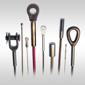
We offer a full line of wire rope and aircraft cable end fittings designed for installation by crimping, clamping, speltering, swageless connectors, or our specialty — machine swaging. Most fitting types are available in a variety of sizes and materials to meet the needs of nearly any application. To complete your assembly, you may also be interested in our wire rope hardware.
As a rigger or end-user of wire rope, it’s important to understand the types of terminations, or treatments, that can be used at the ends of a length of wire rope. These terminations are usually made by forming an eye or attaching a fitting, and are designed to be a permanent end termination on the wire rope where it connects to the load.
Wire rope is an extremely versatile mechanical device that can be used to help support and move an object or load. In the lifting and rigging industries, wire rope is attached to a crane or hoist and fitted with swivels, shackles or hooks to attach to a load and move it in a controlled matter. It can also be used to lift and lower elevators, or as a means of support for suspension bridges or towers.
In this article, we’ll explain what some of the following terms mean and how the can be used to terminate the end of a wire rope cable:Wire rope sockets—spelter sockets, swaged sockets, and wedge sockets
When you understand the construction and specifications of the wire rope you need, as well as the right type of end termination you need, you’ll be able to select the best performing and longest-lasting wire rope for the job at hand.
There are essentially two techniques that can be used to create a termination on a length of wire rope or cable:You can form an eye, or loop, in the wire rope
Eyes, or loops, can be created at one end of a length of wire rope by using a mechanical splice with a swaged sleeve, a hand-tucked splice, or wire rope clips.
A swaged socket is applied to the end of a wire rope cable and is then forced into place using special dies and a hydraulic machine called a swager. When properly applied with the correct sized fitting, swaged sockets have an efficiency rating of 100% of the breaking strength of the rope.
A poured socket, commonly referred to as a spelter socket, attaches a termination fitting onto the end of a wire rope cable by pouring molten zinc or resin into a socket that then hardens and holds the fitting onto the end of the cable.
Due to the rigidity of this type of termination, the wires of the rope are subject to fatigue where the wires enter the socket, if the poured socket is subject to constant vibration.
Wedge sockets secure the rope to the end attachment by passing it around a grooved, wedge-shaped piece of steel and pulling it down under load into the bowl of the fixture.
Wedge sockets are popular because they can be installed in field and adjusted in field – providing 80% efficiency of rope breaking strength. Wedge sockets are popular in applications where the wire rope may be subjected to abuse and abrasion—particularly in construction and mining applications.
Wire rope clips can be used to form a load bearing eye at the end of a cable or wire rope, or to connect two cables together with a lap splice. Wire rope clips are popular because they can be installed in the field and provide 80% efficiency of the rope breaking strength.
However, the use of wire rope clips is heavily regulated by ASME B30.26 Rigging Hardware. When using wire rope clips, the end user must account for the following:When using U-bolt wire rope clips, the saddle shall be placed on the live end of the wire rope, with the U-bolt on the dead-end side—NEVER SADDLE A DEAD HORSE!
After installation, the connection shall be loaded to at least the expected working load. After unloading, the wire rope clips shall be re-tightened to the torque specifications of the manufacturer or a Qualified Person.
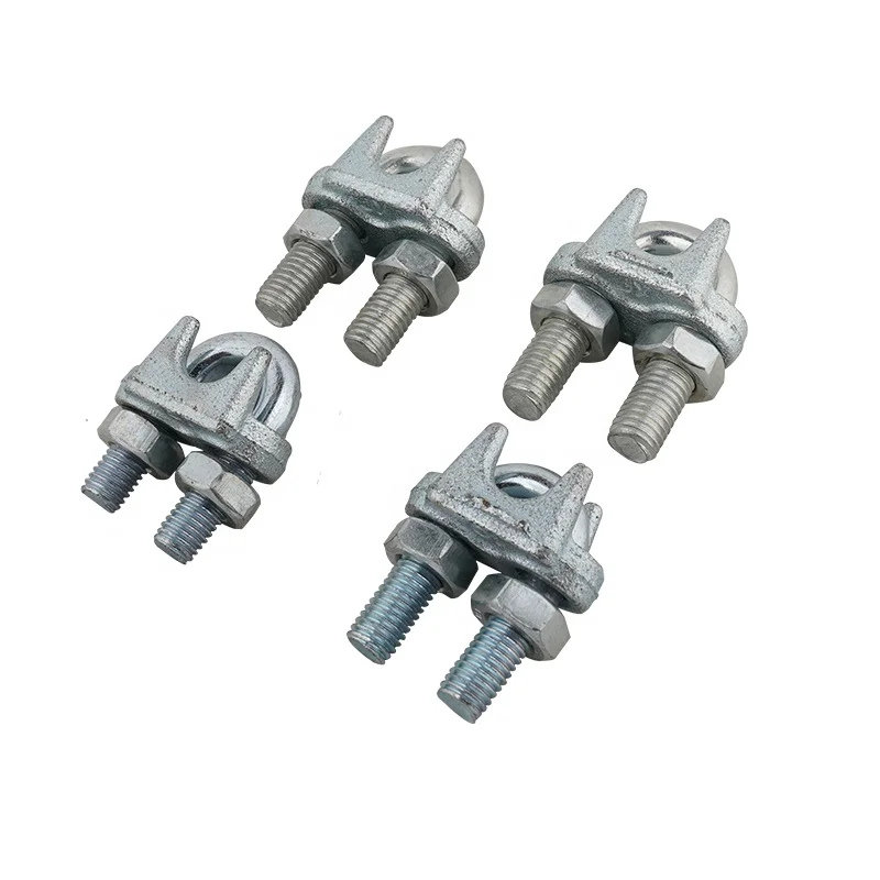
This type of wire rope clip is essentially a U-bolt, two nuts, and a metal base (saddle) that can be made from forged steel or cast iron. Careful consideration and attention must be given to the way U-bolt type wire rope clips are installed.
The base of the wire rope clip is made from forged steel. Forged clips are heated and hammered into the desired shape—resulting in a consistent grain structure in the steel. Forged wire rope clips are used for critical, heavy-duty, overhead loads such as winch lines, crane hoist lines, support lines, guy lines, towing lines, tie downs, scaffolds, etc.
Malleable wire rope clips are used for making eye termination assemblies only with right regular lay wire rope and only for light duty uses with small applied loads, such as hand rails, fencing, guard rails, etc. The base of the wire rope clips is made from malleable cast iron, which may fracture under heavy use and does not have the desirable metal properties of steel, or the beneficial grain structure that a forged base has.
Double saddle wire rope clips consist of two saddles, each with a leg, and two nuts—one used on the top and one on the bottom. Double saddle wire rope clips can be used in either direction, so they take the guesswork out during installation when applying to the live end and the dead end of a piece of wire rope.
An eye splice may be used to terminate the loose end of a wire rope when forming a loop. The strands of the end of a wire rope are unwound and then the wire is bent around, and the unwrapped strands are then weaved back into the wire rope to form an eye.
A Flemish eye splice is created when the wire rope is opened, and the strands are laid out into two parts. The two strands are looped in opposite directions and then laid back together—forming an eye, or loop, at one end of the wire rope cable. The strands are then rolled back around the rope body and a metal sleeve fitting is slipped over the splice and swaged using hydraulic machinery. This splicing method provides the most efficient use of rope capacity and is highly economical.
A hand tucked splice is formed when the shorter “dead” end is tucked into the longer “live” end of the wire rope—forming an eye. These types of splices allow for easy inspection of the wire rope wires and strands.
When the end of a rope is turned back and formed into an eye, a thimble is often used to keep the shape of the eye, prevent the rope from being crushed, and keep the rope from being bent at a diameter smaller than the rope manufacturer’s recommendations.
The table below will explain the efficiencies of the different types of wire rope end terminations for both independent wire rope core (IWRC) and fiber core (FC) wire rope configurations. Rope efficiency is described as the ratio of a wire rope’s actual breaking strength and the aggregate strength of all individual wires tested separately—usually expressed as a percentage.IWRCFC
*Spelter sockets in smaller rope sizes (usually less than 7/16”) may not always develop 100% efficiency and are not recommended by some rope manufacturers.
When you need to order a replacement wire rope, understanding the right type of end termination will help to make sure you get a direct replacement rope so you can get your project back on track. We hope this article gives you a better understanding of terms related to sockets, wire rope clips, and eye splices and that you understand what type of end termination may be best for your application.
At Mazzella, we offer all different kinds of wire rope from all of the leading manufacturers. We sell the highest-quality domestic and non-domestic rigging products because product quality and operating safety go hand-in-hand. We have one of the largest and most complete inventories of both domestic and non-domestic rigging and lifting products to suit your lifting needs.
• Based on the catalog breaking strength of wire rope, Crosby wire rope clip have an efficiency rating of 80% for 3-4mm to 22mm sizes, and 90% for sizes 24-26mm through 90mm.
• Meets or exceed all requirements of ASME B30.26 including identification, ductility, design factor, proof load and temperature requirements. Importantly, these wire rope clips meet other critical performance requirements including fatigue life, impact properties and material traceability, not addressed by ASME B30.26.
Spelter socket terminations have an efficiency rating of 100%, based on the catalog strength of wire rope. Ratings are based on the recommend use with 6×7, 6×19, or 6×36, IPS or XIP (EIP), XXIP (EEIP), RRL, FC, or IWRC wire rope. Strand constructed with minimal number of wires (e.g. 1×7) requires special consideration that socket basket be five (5) times the strand diameter or fifty (50) times the wire diameter, whichever is the greater.
Wedge socket terminations have an efficiency rating of 80% based on the catalog strength of XXIP wire rope.Meets or exceed all requirements of ASME B30.26 including identification, ductility, design factor, proof load and temperature requirements. Importantly, these sockets meet other critical performance requirements including fatigue life, impact properties and material traceability, not addressed by ASME B30.26.Type approval and certification in accordance with ABS 2006 steel Vessel Rules 1-1-17.7, and ABS Guide fo r Certification of Cranes.Basket is cast steel and individually magnetic particle inspected.Pin diameter and jaw opening allows wedge and socket to be used in conjunction with closed swage and spelter sockets.Secures the tail or “dead end” of the wire rope to the wedge, thus eliminates the loss or “punch out” of the wedge.
Eliminates the need for an extra piece of rope, and is easily installed.The TERMINATORᵀᴹ wedge eliminates the potential breaking off of the tail due to fatigue.The tail, which is secured by the base of the clip and the wedge, is left undeformed and available for reuse.
Utilizes standard Crosby Red-U-Bolt® wire rope clip.The 9-10mm through 28mm standard S-421 wedge socket can be retrofitted with the new style TERMINATORᵀᴹ wedge.Available with Bolt, Nut, and Cotter Pin. US patent 5,553,360, Canada patent 2,217,004 and foreign equivalents.Meets the performance requirements of EN 13411-6: 2003.
Wire rope clip is otherwise known as a wire rope clamp, wire cable clamp, wire clamp, wire clip, U-bolt, etc. It is widely used for making eye-loop connections or join two wire rope cable ends together. The traditional styles of wire rope clips usually have three components: a U-shaped bolt, a forged or cast iron saddle, and two nuts.
The wire rope clips are available in a range of sizes and finishes, while you can easily find the difference from the appearance, traditional wire clips with u bolt, saddle and nuts, fist grip, stamped cable clamp.
Cast and malleable wire rope clips can only be used under light duty loads applications with relatively light loads, such as handrails, fencing, guard rails, etc.
While the drop forged wire rope clip variety is recommended for important, critical or sustaining overhead loads, such as guy lines, support lines, scaffolding, etc. The drop forged wire rope clips can be used in critical suspending, guying, and tie-down applications for the die forging process make them strong and more durable and the heating and hammering steps make their structure to be consistent and conform to the shape of the forged item.
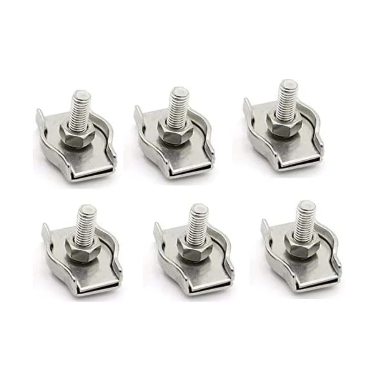
Simplex and duplex cable clamps are also known as single stamped wire clip and double stamped cable clip are composed of stamping plate, saddle, and bolts, feature an aesthetic design, used for outdoor light duty applications.
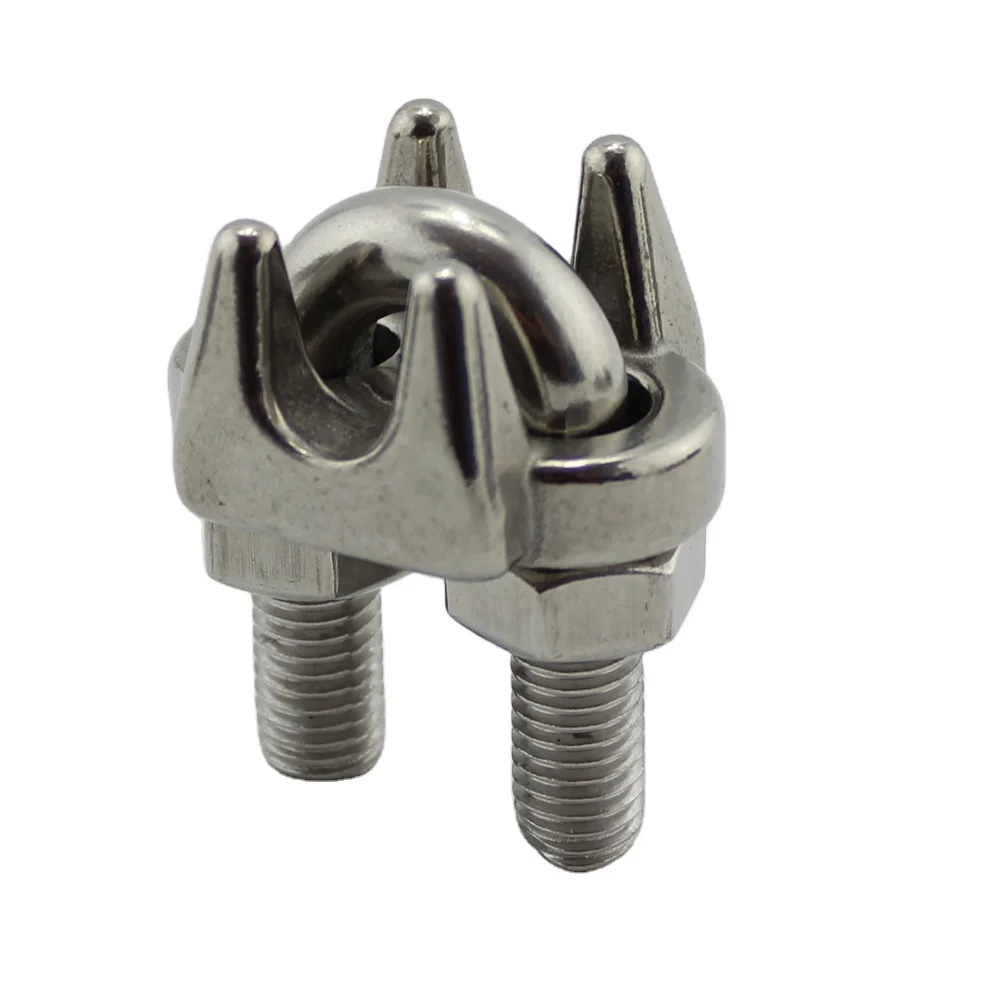
Wire rope clips are available in a variety of materials and finishes but basically three types of materials, carbon steel, cast, malleable iron, and stainless steel.
Carbon steel wire rope cable clamps are galvanized, or hot dipped galvanized, the galvanised metal wire clamp has an added zinc layer to prevent rusting and protect against scratching and the addition of carbon corresponds with an increase in the hardness and strength of wire rope cable clamps. G, but stainless steel wire rope clamps are the best choice for corrosion-resistant applications that can be used for saltwater environments.
Commonly wire rope clamp installation is very simple, there’s a well-known saying can help you remember how to attach wire rope clips, that reads “never saddle a dead horse.” Just follow the recommendation ways:
Keep three or more wire rope clips attached at the end of the wire rope dead end, space between each wire rope clip should be at least 6 times the wire rope diameter.
You can see the correct and incorrect ways of installation from the following pictures and find how many wire rope clips to use at one wire rope loop.
The saddle shall be placed on the live end of the wire rope, with the U-bolt on the dead-end side—Remember the well-known saying: “Never saddle a dead horse.” Use at least two or three wire rope clips to secure the ends properly to the length of the rope, and tighten nuts evenly one by one until reaching the recommended torque.
If you have any wire rope clips questions, you can contact us by email at info@hilifting.com. We will be glad to share with you more useful information.

Simplex wire rope clip is one type of frequently used wire rope clamp. This wire rope clip has a simple design, but with strong and high corrosion resistance. It can be perfect for making eye-loop connections or complete loops in wire rope clip cable, we also have duplex wire rope clip for your option.
In addition to the standard range, SWR supply high quality wire rope fittings for various uses including architectural, marine, yacht rigging and structural applications. SWR"s fittings are sourced from approved factories worldwide and fully supported by test certificates where applicable.

The present invention relates to a wire rope clip. In particular, the present invention is directed to a two-piece bolt and saddle for wire rope clips, which will grip and secure to the exterior surface of a rope or cable.
Previously existing wire rope clips have been forged and comprised of two identical clamps, each having a long threaded leg and an orifice for receiving a threaded leg of the corresponding clamp. The forged pieces were designed to be assembled together for clamping a wire rope. An example of such a wire rope clip is a FIST GRIP® clip manufactured by The Crosby Group, Inc.
Another example of a wire rope clamp is shown in U.S. Pat. No. 3,333,303 to St. Pierre. The St. Pierre wire rope clamp is constructed of two identical forgings secured together by a pair of conventional bolts. The St. Pierre wire rope clamp eliminates the need to forge a long leg on the clamps by replacing the leg with a standard bolt that passes through apertures formed within the clamps. The clamps are provided with a sunken hexhead socket for making the bolt heads non-rotatable. Although the sunken hexhead provided on the forged piece prevents rotation of the bolt, the sunken hexhead does not secure the bolts within the apertures of the unassembled clamps. Since the bolts are free to slide in or out of a clamp, difficulties arise in assembling the completed wire rope clamp.
It is an additional object to provide a wire rope clamp wherein a bolt is non-rotatable and is removably secured in a respective saddle so that the wire rope saddle may be assembled with greater ease without the difficulties associated with unintentional bolt disengagement from the saddle.
The wire rope clip of the present invention includes a first and second bolt each having a head, a threaded end and a plurality of splines. The splines are fashioned on the bolts proximate the head. The first bolt is received in a first orifice fashioned in a first saddle. The second bolt is received in a first orifice fashioned in a second saddle. The bolts are preferably press fit into the orifices whereby the splines on the bolts engage the walls of the first orifices so that the bolts are removably secured therein. The splines not only prevent rotation of the bolts, but also keep the bolts secured into their respective saddles.
Additionally, each saddle has a second orifice fashioned therein. The second orifice of the first saddle is for receiving the threaded end of the second bolt. The second orifice of the second saddle is for receiving the threaded end of the first bolt. The saddles are secured together by means of a first nut and a second nut that bias against the base of the second saddle and the base of the first saddle, respectively. Both the first saddle and the second saddle have a rope engaging surface fashioned between their respective first orifice and second orifice. Each rope engaging surface is fashioned on the surface opposite the base of each saddle. The wire rope clip is preferably constructed such that the first orifice on the first and second saddles are provided with a chamfered recess proximate the base of each respective saddle for receiving bolts having countersunk heads. By constructing the wire rope clip in this manner, the heads of the first and second bolts are flush with the base of the first and second saddles.
By constructing the two identical saddles, and securing the saddles together by means of the first bolt and the second bolt, a wire rope may be securely clamped by the wire rope clip.
Referring to the drawings in detail. FIG. 1 illustrates a preferred embodiment of first saddle 10 and first bolt 12 of the wire rope clip. First saddle 10 is provided with first orifice 14 and second orifice 16. Additionally, first saddle 10 is provided with rope engaging surface 18 and base 20 formed on an opposite side thereof.
In the preferred embodiment, first orifice 14 is formed having a chamfered recess 22 in base 20. First orifice 14 receives first bolt 12. First bolt 12 is preferably provided with head 24, threaded end 26 and splines 28. The splines 28 in the present embodiment are parallel to the axis of the first bolt. The head 24 is preferably countersunk to correspond with chamfered recess 22. Splines 28 or ribs engage wall 30 of first orifice 14. The splines 28 interfere with or dig into wall 30 of first orifice 14 for preventing first bolt 12 from rotating within first orifice 14 and for securing first bolt 12 within first orifice 14.
Although FIG. 1 displays first saddle 10 and first bolt 12, it is to be understood that, in the preferred embodiment, a second saddle and a second bolt are identical thereto and function in the same manner.
Referring to FIG. 2, an exploded side elevation view of a wire rope clip is provided. First saddle 10 is shown with first bolt 12 affixed thereto. First bolt 12 preferably is press fit within first orifice 14. It is noted that chamfered recess 22 receives countersunk head 24 as shown in FIG. 1, thereby resulting in flush surface 32. Opposite first saddle 10 is second saddle 34. Second saddle 34 is shown with second bolt 36 affixed thereto. Second bolt 36 is preferably press fit within first orifice 38 formed in second saddle 34. Additionally, second orifice 40 is provided in second saddle 34.
Second saddle 34 is provided with rope engaging surface 42 on one side and base 44 on an opposite side. Similar to first saddle 10, second saddle 34 also has a chamfered recess for receiving a countersunk head of second bolt 36. Second bolt 36 includes a threaded end 46 and splines or ribs, similar to first bolt 12. The union of the chamfered recess of second saddle 34 and the corresponding countersunk head of second bolt 36 result in flush surface 48 on base 44 of second saddle 34.
Threaded end 26 of first bolt 12 passes through second orifice 40 of second saddle 34 and engages first nut 50. Similarly, threaded end 46 of second bolt 36 passes through second orifice 16 of first saddle 10 for engaging second nut 52. First nut 50 biases against base 44 of second saddle 34 and second nut 52 biases against base 20 of first saddle 10. Therefore, rope engaging surface 18 of first saddle 10 is positioned opposite rope engaging surface 42 of second saddle 34. Rope engaging surfaces 18 and 42 are designed to engage a wire or other type of rope therebetween to secure the rope therein.
By utilizing the wire rope clip of the invention, first nut 50 and second nut 52 can be installed in such a way as to enable an operator to swing a wrench in a full arc for fast installation.
In practice, first bolt 12 is press fit or forced within first saddle 10 and splines 28 engage wall 30 within first orifice 14 of first saddle 10. Splines 28 prevent first bolt 12 from rotating within first saddle 10. Additionally, splines 28 removably secure first bolt 12 within first orifice 14. A similar assembly is constructed with respect to second saddle 34 and second bolt 36. By providing splines 28 for engaging wall 30 of first orifice 14 and for engaging the wall of second orifice 38 of second saddle 34, an operator is not inconvenienced by accidental disengagement of first bolt 12 from first sadole 10 and/or accidental disengagement second bolt 36 from second saddle 34.
First saddle 10 is positioned such that rope engaging surface 18 engages a wire rope and positions second saddle 34 such that threaded end 26 of first bolt 12 passes through second orifice 40 of second saddle 34. Additionally, second saddle 34 is positioned such that rope engaging surface 42 also engages a wire rope. First nut 50 is then threaded over threaded end 26 of first bolt 12 and second nut 52 is threaded onto threaded end 46 of second bolt 36. In this manner, two pieces of wire rope may be securely clamped by the wire rope clip of the present invention.
The wire rope clips may be utilized on turnback loops formed from a single piece of cable or to splice two pieces of wire rope together. It is to be understood that the wire rope clips may also be utilized for other applications where traditional wire rope clips have been utilized.


 8613371530291