
wire rope bracing quotation

For over 60 years, Loos & Co., Inc. has pioneered and thrived in the highly critical profession of wire, wire rope, and hardware manufacturing for use in applications critical outcomes are directly at stake. This valuable experience has taught us “the ropes” about what a difference quality and performance make in your applications. Now, we can help make the difference for you with your pulley and sheave applications, too.
We’re proud to offer a wide variety of military specification and commercial wire rope, aircraft cable, and fittings to compliment your complete sheaves or pulley system. These products are the perfect compliment to the high performance products offered by esheaves.com. Pairing Loos & Co., Inc. tools, hardware, and accessories with the highest quality pulleys and sheaves will repay you with the performance you have come to expect from our products.

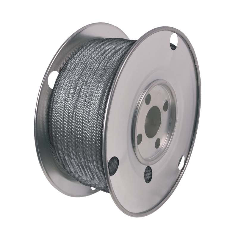
Cables are a construction of wire strands, laid (i.e. twisted) helically around a core, to form a tension member of symmetrical cross-section. Cables have a high strength-to-weight ratio as the wire strands are drawn to high strengths and laid to share tensile loads efficiently. There are two fundamental cable constructions: Wire rope (“flexible construction”) and structural strand (“stiff construction”). The construction and subsequent mechanical properties are determined by the wire pattern and wire size used for the core and outer strands.
For a given strength, wire rope is larger in diameter and lower in stiffness than structural strand or solid rods, so it may not be the most cost-effective product for static, tension load-carrying structural members. However, wire rope may be the appropriate choice in cases where relatively high stretch is desired or where the cable needs to turn a sharp angle. Typical constructions are 7×19 and 6×19 IWRC.

The next generation of wire rope suspension products designed for the fast suspension of cable containment, pipework, ductwork, HVAC systems and modules, including multi-tier installations.
The next generation of wire rope suspension products designed for the fast suspension of cable containment, pipework, ductwork, HVAC systems and modules, including multi-tier installations.
The next generation of wire rope suspension products designed for the fast suspension of cable containment, pipework, ductwork, HVAC systems and modules, including multi-tier installations.
The next generation of wire rope suspension products designed for the fast suspension of cable containment, pipework, ductwork, HVAC systems and modules, including multi-tier installations.
The next generation of wire rope suspension products designed for the fast suspension of cable containment, pipework, ductwork, HVAC systems and modules, including multi-tier installations.
The next generation of wire rope suspension products designed for the fast suspension of cable containment, pipework, ductwork, HVAC systems and modules, including multi-tier installations.
The next generation of wire rope suspension products designed for the fast suspension of cable containment, pipework, ductwork, HVAC systems and modules, including multi-tier installations.

nVent products shall be installed and used only as indicated in nVent"s product instruction sheets and training materials. Instruction sheets are available at www.nvent.com and from your nVent customer service representative. Improper installation, misuse, misapplication or other failure to completely follow nVent"s instructions and warnings may cause product malfunction, property damage, serious bodily injury and death and/or void your warranty.
You might want to look at a safety factor of 2 or 3 for the cable and a safety factor of 5 for the fasteners... just a place to start, and be comfortable with what you decide. RE: FS for Cable X-Bracing?
According to Structural Steel Designer"s Handbook, a common design factor (breaking strength/expected load) suggested in the AISI publication "Wire Rope Users Manual" is 5.
Thanks for the reference. What got me wondering about the "correct" FS is regular building components (beams, columns etc) the we use 1.7 for live loads; for lifting with cables we use 3 or 5. For the cable braces used in a building for wind bracing, should we use 1.7 (I don"t think so) or 5 like in lifting (I don"t think so)?
For seismic, you would use the special load combinations used for connection design. This involves the Omega factor in the IBC or other similar factors. In addition, I would ensure that the cable would totally yield prior to the more brittle connection at each end would fail. For standard clevises or socketed connections this may be difficult but the key is to let the cable yield prior to the end connection failing. You want as ductile a connection as possible. RE: FS for Cable X-Bracing?
The kicker with cabling is the connection... hence the higher safety factor suggested... You have to be careful in not reading too much into safety factors for cables used for handling materials... they are subject to a lot of abuse, and this is reflected in an increased factor of safety... RE: FS for Cable X-Bracing?
haynewp has rightly pointed out the general factor of safety of 5 (minimum) for steel wire ropes. However the comparison of this figure of "5" to "1.7" of general fabrication steel is meaningless as there is no "yield point" for wire ropes. This FS of 5 is applied to breaking strength of rope, the only measuable property for ropes, whereas FS of 1.7 is generally applied to Yield Stres of steel for structural steel.
The point is, we can draw a elasticity curve for steel and mark out a yield point. In ropes, such exercise will not be of much use because the ropes un-twine and elongate even with slight load. An FS of 5 on breaking capacity of rope does not mean that it is far safer than structural steel having an FS of only 1.7 on its yield point. RE: FS for Cable X-Bracing?
While doing some additional research on this, I skimmed through the book "Metal Building Systems, Design and Specifications" by Alexander Newman. On page 38 he shows a detail of a hill-side washer with an eye bolt for a connection with cable X-bracing - a standard detail I"ve seen many times. On page 40 he shows a photo of a fractured hill-side washer as a result of the Northridge Earthquake and the eye-bolt nearly pulled through the column web.
I"m not in a seismic zone, so I"ve never seen this before. However, it does bring up the question of checking the column or beam web for bending in connections like this, even from wind loading. Anyone actually doing this? RE: FS for Cable X-Bracing?
I would use a SF of 2.0 for cable. This is consistent with TIA/EIA 222 Standard which requires FS of 2.0 for guy cables. I see the bracing cable in metal building to be not any different from that of a guy cable (carries wind load in tension only).
The SF of 5.0 for material handling is used due to the criticality of the function and potential misuse, as stated by dik. OSHA requires these material handling cables (wire ropes) to be replaced when certain number of kinks, broken strands are evident.
I would have to agree with Lufti on this one. And definitely consider using EHS 7 strand guy wire for this, not wire rope. One of the reasons that wire rope has a minimum SF of 5 is because of its flexibility and the continuous wear it is subjected to in moving over pulleys and sheaves. This is not the case with guy wires for utility poles or communication towers.
EIA does specify a SF of 2.0, and I believe the main reason for this is the assurance that the cable never gets close to its yield point (and, yes, guy wires DO have a yield point that can be measured by the tangent offset method). The main point is that a guy wire and a pole, tower or frame in a metal building all will act a a single structure and will take load according to their initial tension and relative stiffness. Hence, the resulting deflections and member stresses can be predicted as long as the wire does not yield. That is the real issue here. Once the cable yields, you don"t know what the member stresses are in the structure.
I also totally agree with those who empahsize the proper treatment of the connections. All else being equal, if you have a problem with a guyed structure, it will likely be in the connections. RE: FS for Cable X-Bracing?
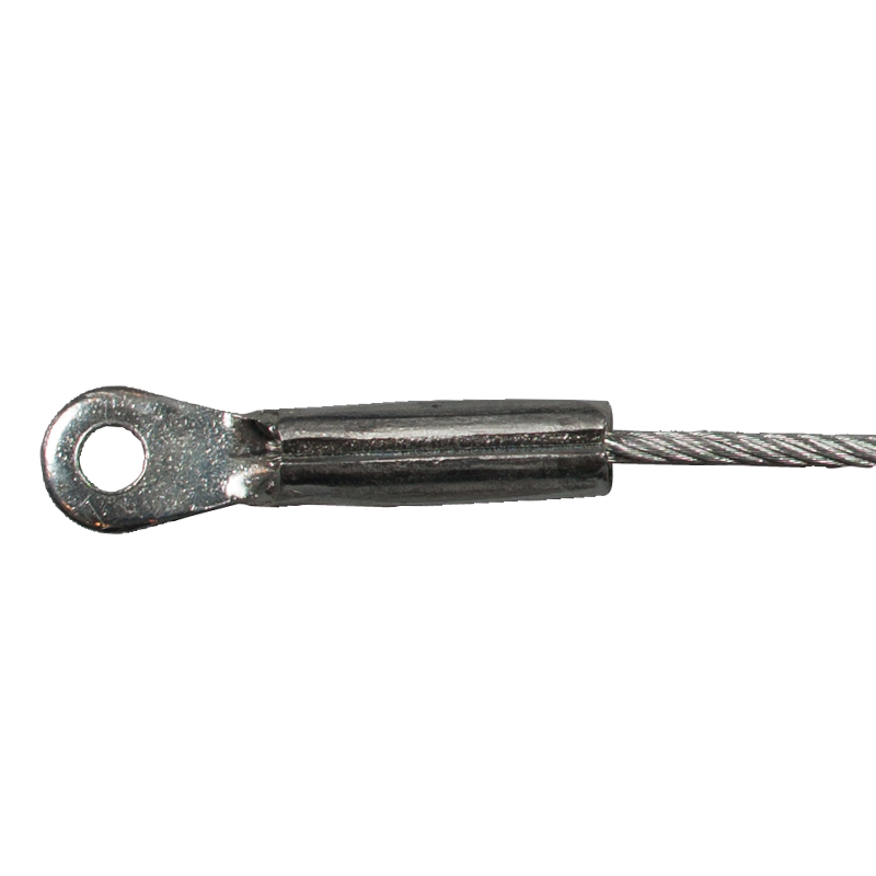
For the cable itself, ASCE 19-96 (Structural Applications of Steel Cables for Buildings) indicates the use of a 2.0 safety factor is acceptable for wind or earthquake loads. The end connectors should be capable of developing 110% of the nominal cable strength. RE: FS for Cable X-Bracing?
VOD mentioned cables stretching. They certainly do "stretch" more than solid steel, but it is not a problem for design. The Modulus of Elasticity varies with the ropes construction. I have some published values that vary from 86 to 138 GPa, with most in the range 103-115GPa, and a representative value of 110 GPa. (For imperial units readers, solid steel is 200 GPa). When analysing/modelling the rope, this reduced value of E is to be used with the "metallic" cross-section area of the rope. RE: FS for Cable X-Bracing?
Can you fax me or eMail me the published values? If faxed, I"ll scan them and convert to *.pdf"s for general distribution. Fax 705 324-5852, eMail dikcoates@alpha.to RE: FS for Cable X-Bracing?
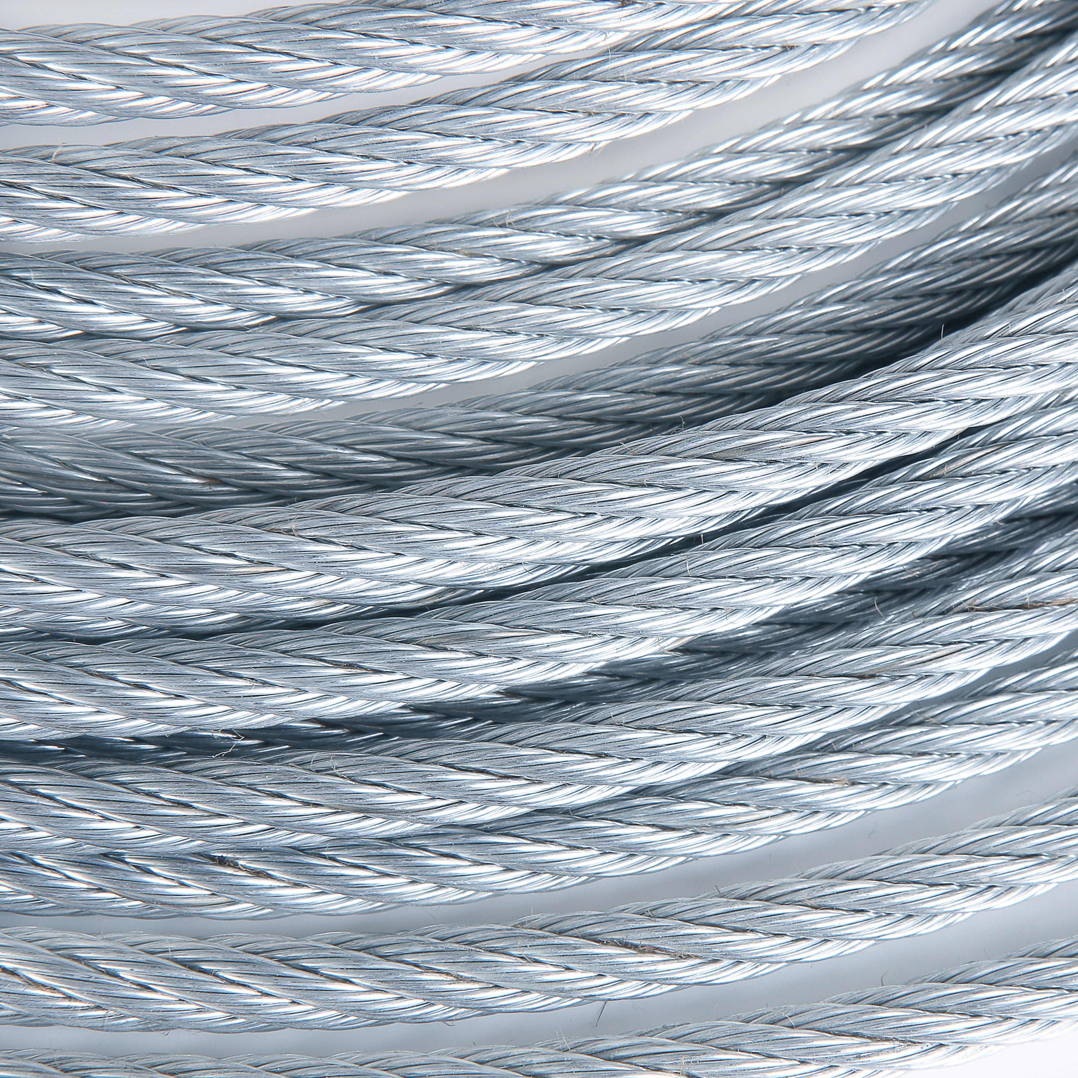
A wire rope subject to a tensile force initially extends as the overall diameter reduces until the adjacent wires contact each other. This is a permanent extension, and can not be accurately predicted. As a guide, assume 0.25 to 1% extension.
Note that these are typically 20 to 70 mm diameter ropes used for mine hoisting. They are designed, among other things, to minimise rotation and stretch. If you had a general purpose rope with a simple construction and you did not have details of E, I would guess that an E value of 85 GPa or even less might be appropriate.

Lexco®is an industry-leading manufacturer of wire rope and cable assemblies for the construction industry. Our cable assemblies make ideal solutions for use cases ranging from large-scale commercial building projects to routine maintenance work, heavy-duty equipment, construction safety, and more.
We understand that success is about more than just being tough—it"s also about being consistent. Our stainless steel cable and wire rope assemblies offer a high strength to weight ratio in addition to being long-lasting, low-maintenance, flexible, and providing a cost-efficient solution for many different construction applications. Whether you"re engaged in developing heavy-duty equipment, a general contractor building a new home, or are building a complete commercial complex; our experienced team is here to help you find the construction cable assembly that"s right for you.

PersonalWe are on hand to personally guide you through the entire process, we translate the jargon, we recommend what’s best, and we are always here in person. No nonsense, just straight talking people who always exceed expectations through our extensive wire rope knowledge and superior service.
Wire-rope bracing system with a central cylinder is a modern bracing system, which can be used in strengthening steel and concrete Moment Resistant Frame (MRF). This paper is focused on several multistory steel MRFs with cable-cylinder bracing subjected to seismic loads. In this regard multi-story steel MRFs are analyzed with and without cable bracing systems. The effectiveness of cable-cylinder bracing system is then discussed by the obtained results. A model of MRF with cable-cylinder bracing…Expand

Cable tie D6 is one of the cables that many people prefer to use for work in many different fields. The reason for bracing is highly appreciated because there are many outstanding features such as:
Bracing cables have strong durability, because they are manufactured according to a modern line, varying the right specifications. Therefore, they have rugged durability. If used to anchor, bracing objects in compliance with the prescribed load to ensure no abrasion, fracture during work.
Bracing cables are highly resistant, they can withstand a lot of external forces without explo the quality of cables. With this feature, bracing cables are often used in many construction projects requiring high bearing capacity.
Price quotes bracing is always a problem many buyers are most concerned today. Because there are so many prices on the market, they cannot calculate the cost they need to prepare to own the product.
Come to Le Ha Vina you will be consulted, introduced in detail about each type of bracing cables. Then, based on these information, your staff requirements will quote in detail. We will help you calculate the cost if you want to buy the product.
Above are the outstanding features of D6 bracing cable that you should grasp. If you have any questions would like to be answered please contact us immediately.
This invention relates generally to building construction methods and apparatus, and more specifically to an improved cable hold down and bracing system that ties building components together or to the ground, providing stabilization and resistance to uplift or overturning caused by wind, ground movement, earthquakes, or similar forces.
The cable hold down and bracing system of this invention provides a method and apparatus for tying building components together or to the ground, providing stabilization and resistance to uplift or overturning caused by wind, ground movement, earthquakes, or similar forces. The inventive system uses a system of cables or rods strung between the foundation or other base and the top corners of any shear diaphragm. The invention"s cables are kept under tension regardless of the shrinkage of wooden components, providing evenly-distributed compression on the structure"s framing members. As a result, any relative movement caused by vertically applied ("uplift") forces or horizontally applied forces is prevented from the first moment of application, greatly reducing the damage typically attributed to impact loading. This differs from the destructive effect of vertical and horizontal movement on traditional "hold-down" techniques, which cannot adjust to the slack caused by the shrinkage of wood framing, making them highly vulnerable to impact loading stresses. The inventive system may also be used with metal framing instead of wood.
This creates a highly unified, rigid structure capable of resisting uplift and overturning forces. By incorporating specially-designed stranded wire rope or cables, springs, and brackets, the inventive system maintains an evenly-distributed compression amongst structural framing members over the life span of a structure, regardless of dimensional changes caused by wood and/or increased loads that may be imposed due to earthquakes, soil movement, settling, hurricane, typhoons, or similar forces.
FIG. 1 is a cutaway side elevation view of a cable hold down and bracing system of this invention, illustrating the components and assembly of the inventive system.
FIG. 1 is a cutaway side elevation view of a cable hold down and bracing system of this invention, illustrating the components and assembly of the inventive system. The inventive system may be installed in the following manner:
1. An anchor bolt 36 is embedded in the foundation 16 of the structure, extending through a drilled hole 20 in the mud sill 24. This will serve as the lower securement point for the stranded wire rope 46, which ties the foundation to the top of the shear diaphragm(s).
2. An anchor bolt strap component 40, which is a rectangular steel box that has a hole through the single thickness short side 40a and a hole through both thicknesses of the double thickness short side 40b, is secured to the mud sill 24 by a nut 32 threaded on the anchor bolt 36 and tightened against a square flat washer with a round hole 28a (washer 28a prevents distortion of the long legs of the anchor bolt strap 40 and provides a seat against which the nut 32 is tightened). The double thickness short side 40b of the anchor bolt strap component 40 faces the mud sill 24. The anchor bolt strap 40 transmits forces from the anchor bolt 36 to the "dead-end" cinching device 44a and in turn to the stranded wire rope 46.
3. A "dead-end" device or other cable gripping device 44a, comparable in design, function, and strength to that offered by Fargo Manufacturing Company, P.O. Box 2900, Poughkeepsie, N.Y. 12063 is inserted through the hole of a square flat washer 28b (washer 28b prevents distortion of the long legs of the anchor bolt strap 40 and provides a seat for the shoulder of "dead-end" cinching device 44a which grips the stranded wire rope 46). This assembly passes up through the hole of the single thickness short end 40a of the anchor bolt strap 40.
Note: The components described in items #1-3 above simply provide a means of securely affixing the stranded wire rope 46 to the foundation 16. This arrangement is not vital nor important to the function of the invention. For example, the anchor bolt strap 40 can extend into the foundation 16, eliminating the need for the anchor bolt 36, nut 32, and square flat washer 28a. With reduced loads, washer 28b can be eliminated.
4. The stranded wire rope or cable 46 extends through hole 21 in the structure"s subfloor 56 and sole plate 60 (which are separated from mud sill 24 by floor joist 48), and hole 23 in top plates 68 (which are separated from sole plate 60 by vertical framing members 64). The stranded wire rope 46 is passed up through any other intervening horizontal (or perpendicular) framing members to the last in-line horizontal (or perpendicular) framing member 68 of the shear diaphragm.
6. A "dead-end" cinching device 44b is inserted over the stranded wire rope 46 and through the hole in the flat metal plate 72. The "dead-end" device transfers the load from the stranded wire rope 46 to the top plate 68, evenly distributing the forces generated by earthquake, wind, or other external forces and restricting any movement of the top of the shear diaphragm relative to the ground or other attachment points.
7. A further "dead-end" device 44c is inserted in one end of a compression spring 80. This assembly is then placed over the stranded wire rope 46 and on the top of the flat metal plate 72.
8. The stranded wire rope 46 is then pulled taut, and force is applied to the top of the "dead-end" device 44c, causing the "dead-end" device 44c to slide down the stranded wire rope 46 to compress the spring 80 against "dead-end" cinching device 44b, keeping "dead-end" cinching device 44b and the metal load spreading plate 72 in direct contact with the structure"s top plate 68.
The stranded wire rope may be tensioned by pulling the stranded wire rope away from "dead-end" cinching device 44c while simultaneously exerting force against the top of "dead-end" cinching device 44b until the metal spring 80 is properly compressed. This tensioning may be accomplished by any number of existing or specialized tools.
As the wooden framing of a structure shrinks or settles over time, slack in the stranded wire rope 46 is continually eliminated. The metal spring 80, under constant compression, forces the "dead-end" cinching device 44b down on the cable to the point at which metal load spreading plate 72 remains in contact with the structure"s top plate (horizontal framing member) 68. The "dead-end" cinching device 44b has an internal spring that forces the wedges to be repositioned on the stranded wire rope 46.
In the event of an earthquake, sudden earth movement, high winds, hurricane, or similar force that causes uplift, the structure" top plate 68 typically moves away from the foundation. When this occurs, the metal load spreading plate 72 causes the "dead-end" cinching device 44b to grip the stranded wire rope 46, maintaining tension on the stranded wire rope 46 and preventing further movement. This dynamic adaptation resists separation, uplift, and overturning forces.
When properly installed, the inventive system provides continuous connection (rigidity) between the top of a structure"s shear diaphragms and the structure"s foundation. This rigidity prevents damage from uplift, downward forces, or overturning forces typically caused by settling of soil, sudden or gradual earth movements, earthquakes, high winds, and hurricanes.

Send us any information you have on your required cable or wire rope assembly. You can do that via this web-site or fax to 860-974-2967. NCA would appreciate the opportunity to discuss your assembly or lanyard needs with you.
Generally, yes. We ask that you make a minimum order of at least $100. If you are in need of a small number of cable or wire rope assemblies, please contact our team at NCA to see if we are able to assist you.
Most often NCA sales are exempt from sales taxes. Sales taxes are assessed on retail sales, which are sales to the ultimate user or consumer of the item being sold. Since NCA is primarily an OEM fabricator and provides product for other companies’ end-products, we are exempt from charging sales taxes on our cable and wire rope assemblies.
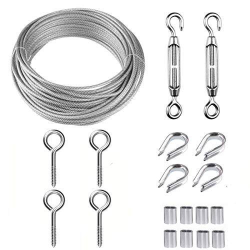
Koala Equipment - Wire ropes sales for aerial parks : Galvanized wire rope, lang"s lay galvanized wire rope, galvanized swaged wire rope IWRC, wire rope for life line, wire rope for zip line, wire rope for zip wire, obstacle supporting wire rope, brace cable, coated wire rope for handrail, wire rope for safety loop, wire strand core, fiber core, swaged thimbled wire rope, wire rope clip, solid rope thimble, wire rope thimble, ferrule, turnbuckle, hydraulic crimping tool, die, cutter, cable puller, lever hoist...

CWI companies manufacture and stock the broadest range of domestic aircraft cable and wire rope in the USA, available to commercial and military specifications in stainless steel, galvanized carbon steel, and a variety of other alloys. We provide products "made and melted in America", "Made in the USA" through our United States based manufacturing facility that ensure your supply chain meets the Buy American Act or the Buy America Act when required. CWI is a fully integrated manufacturer: drawing wire, stranding cable, extruding jacketing material and providing custom products, configurations and processes when you require them.


 8613371530291