
wire rope break test quotation

Get a range of wholesale wire rope break load test designed for different testing needs. For those involved in the field of digital electronics and who need to work with digital circuits and systems regularly, consider the wide range of logic analyzers that are available. Quality testing equipment will be able to help verify and debug your digital designs efficiently when required.
If you are looking for items like electric tester pens for personal or home use, pick from the range of voltage detector kits available. For those who do not require an entire kit, look into the individual product listings for the different types of pen voltage testers that are on sale instead.
For owners of electronic tools and equipment supply stores, there is also a large variety of testing equipment that you might want to consider purchasing. Products that are available include vector network analyzers, circuit breaker testers, megohmmeters and even tube testers. Get wire rope break load test from several popular and leading brands here.
If you happen to be in search of an affordable tool for troubleshooting purposes, consider equipment like the amp clamp meter for quick and effective checking. For those looking for more specialized products, like tools to test fiber optic cables, look into the selection of quality optical time-domain reflectometers, also known as the OTDR, which are used to test the integrity of fiber cables.
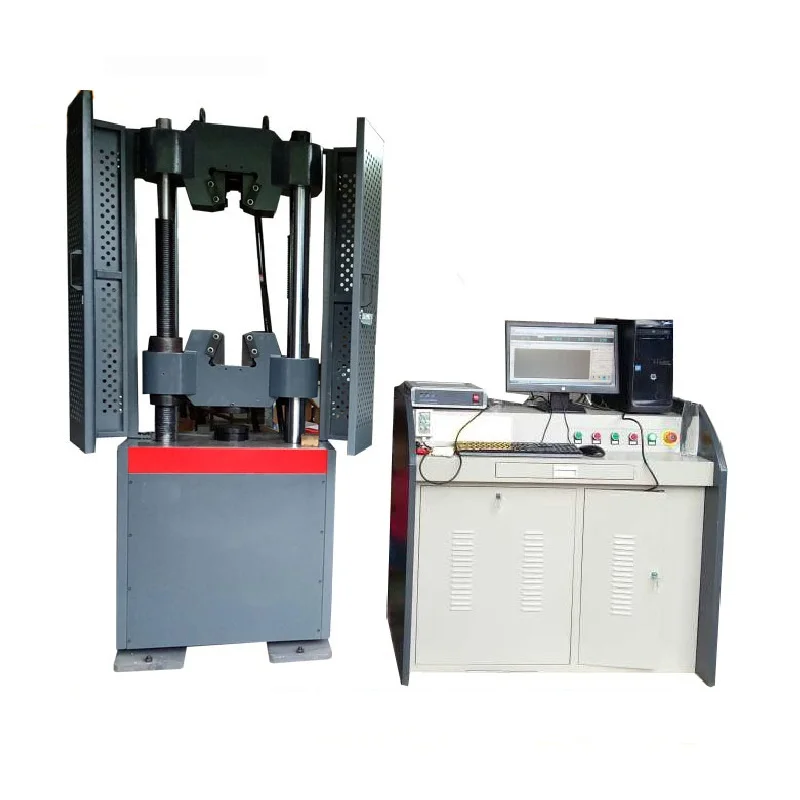
As a company that focuses on quality, testing is at the heart of everything we do. We are LEEA accredited and have state-of-the art testing equipment to ensure all components are tested to the highest industry standards.
Proof load testing is generally performed with the Working Load Limit (WLL). The assembly is subjected to this load and monitored over time. As standard, we perform proof load testing of two times WLL (up to 30 tons) for two minutes. But we can change this criteria to meet your requirements.

Rope strength is a misunderstood metric. One boater will talk about tensile strength, while the other will talk about working load. Both of these are important measurements, and it’s worth learning how to measure and understand them. Each of these measurements has different uses, and here we’re going to give a brief overview of what’s what. Here’s all you need to know about rope strength.
Each type of line, natural fiber, synthetic and wire rope, have different breaking strengths and safe working loads. Natural breaking strength of manila line is the standard against which other lines are compared. Synthetic lines have been assigned “comparison factors” against which they are compared to manila line. The basic breaking strength factor for manila line is found by multiplying the square of the circumference of the line by 900 lbs.
As an example, if you had a piece of ½” manila line and wanted to find the breaking strength, you would first calculate the circumference. (.5 X 3.14 = 1.57) Then using the formula above:
To calculate the breaking strength of synthetic lines you need to add one more factor. As mentioned above, a comparison factor has been developed to compare the breaking strength of synthetics over manila. Since synthetics are stronger than manila an additional multiplication step is added to the formula above.
Using the example above, letÂ’s find the breaking strength of a piece of ½” nylon line. First, convert the diameter to the circumference as we did above and then write the formula including the extra comparison factor step.
Knots and splices will reduce the breaking strength of a line by as much as 50 to 60 percent. The weakest point in the line is the knot or slice. However, a splice is stronger than a knot.
Just being able to calculate breaking strength doesn’t give one a safety margin. The breaking strength formula was developed on the average breaking strength of a new line under laboratory conditions. Without straining the line until it parts, you don’t know if that particular piece of line was above average or below average. For more information, we have discussed the safe working load of ropes made of different materials in this article here.
It’s very important to understand the fundamental differences between the tensile strength of a rope, and a rope’s working load. Both terms refer to rope strength but they’re not the same measurement.
A rope’s tensile strength is the measure of a brand-new rope’s breaking point tested under strict laboratory-controlled conditions. These tests are done by incrementally increasing the load that a rope is expected to carry, until the rope breaks. Rather than adding weight to a line, the test is performed by wrapping the rope around two capstans that slowly turn the rope, adding increasing tension until the rope fails. This test will be repeated on numerous ropes, and an average will be taken. Note that all of these tests will use the ASTM test method D-6268.
The average number will be quoted as the rope’s tensile strength. However, a manufacturer may also test a rope’s minimum tensile strength. This number is often used instead. A rope’s minimum tensile strength is calculated in the same way, but it takes the average strength rating and reduces it by 20%.
A rope’s working load is a different measurement altogether. It’s determined by taking the tensile strength rating and dividing it accordingly, making a figure that’s more in-line with an appropriate maximum load, taking factors such as construction, weave, and rope longevity into the mix as well. A large number of variables will determine the maximum working load of a rope, including the age and condition of the rope too. It’s a complicated equation (as demonstrated above) and if math isn’t your strong point, it’s best left to professionals.
However, if you want to make an educated guess at the recommended working load of a rope, it usually falls between 15% and 25% of the line’s tensile strength rating. It’s a lotlower than you’d think. There are some exceptions, and different construction methods yield different results. For example, a Nylon rope braided with certain fibers may have a stronger working load than a rope twisted out of natural fibers.
For safety purposes, always refer to the information issued by your rope’s manufacturer, and pay close attention to the working load and don’t exceed it. Safety first! Always.
If you’re a regular sailor, climber, or arborist, or just have a keen interest in knot-tying, be warned! Every knot that you tie will reduce your rope’s overall tensile strength. Some knots aren’t particularly damaging, while others can be devastating. A good rule of thumb is to accept the fact that a tied knot will reduce your rope’s tensile strength by around 50%. That’s an extreme figure, sure, but when it comes to hauling critical loads, why take chances?
Knots are unavoidable: they’re useful, practical, and strong. Splices are the same. They both degrade a rope’s strength. They do this because a slight distortion of a rope will cause certain parts of the rope (namely the outer strands) to carry more weight than others (the inner strand). In some cases, the outer strands end up carrying all the weight while the inner strands carry none of it! This isn’t ideal, as you can imagine.
Some knots cause certain fibers to become compressed, and others stretched. When combined together, all of these issues can have a substantial effect on a rope’s ability to carry loads.
Naturally, it’s not always as drastic as strength loss of 50% or more. Some knots aren’t that damaging, some loads aren’t significant enough to cause stress, and some rope materials, such as polypropylene, Dyneema, and other modern fibers, are more resilient than others. Just keep in mind that any knots or splices will reduce your rope’s operations life span. And that’s before we talk about other factors such as the weather or your rope care regime…
Holloway Houston sets the standard in testing solutions. We perform proof load and break tests of up to 10,000 tons on wire rope, synthetic ropes, slings and assemblies, oilfield equipment and tools, and a variety of specialty products.

The lifetime of wire rope is crucial in industry manufacturing, mining, and so on. The damage can be detected by using appropriate nondestructive testing techniques or destructive tests by cutting the part. For broken wires classification problems, this work is aimed at improving the recognition accuracy. Facing the defects at the exterior of the rope, a novel method for recognition of broken wires is firstly developed based on magnetic and infrared information fusion. A denoising method, which is adopted for magnetic signal, is proposed for eliminating baseline signal and wave strand. An image segmentation method is employed for parting the defects of infrared images. Characteristic vectors are extracted from magnetic images and infrared images, then kernel extreme learning machine network is applied to implement recognition of broken wires. Experimental results show that the denoising method and image segmentation are effective and the information fusion can improve the classification accuracy, which can provide useful information for estimating the residual lifetime of wire rope.
Wire ropes play an important role in many fields such as cranes, oil drilling rigs, elevators, and mine hoist. The safety of wire ropes is closely related to people’s life and resources loss as well as the normal operation of industry. Because of the complex structure of wire ropes and the diversity of application environment, it is difficult to evaluate the health of wire ropes in service [1, 2]. Thus, it is necessary to effectively and accurately perform the quantitative nondestructive testing (NDT) of wire rope by adopting proper methods.
At present, the NDT methods of wire rope include electromagnetic [3, 4], X-ray [5], acoustic [6–9], and optical [10] method [1]. X-ray apparatus has radioactive contamination; acoustic method detects wire rope by striking, which is simple but one-sided; CCD camera optical testing method can directly show the real defects through imaging, but it is susceptible to oil pollution; because of high sensitivity, high speed, and low cost, electromagnetic NDT method is widely used [11–14]. However, no single nondestructive testing technique can identify all kinds of defects. Infrared nondestructive testing does not contain dangerous radiation and has characteristic of noncontact; thus, it has widely applied in solving real problems in numerous areas [15].In addition, its popular application areas contain building sector [16, 17], aeronautics and astronautics [18], chemical industry [19], food [20], cultural heritage [21], and so on. Munoz et al. [22, 23] determined heat source dissipation from infrared thermographic measurements based on the heat diffusion equation provided by thermodynamics principles and identified damage evolution in carbon fibre reinforced composites combing acoustic emission and infrared thermography.
Magnetic flux leakage (MFL) detection of wire rope mainly includes the forward calculation model of MFL detection, pretreatment of MFL signal, and inversion of defect [24]. For example, Yan et al. [25] employed a three-dimensional finite element method (FEM) to analyze MFL signals. This method provided theoretical guidance for detection signal analysis and hardware design. Based on the magnetic dipole model, Yang [2] created the leakage magnetic field analysis models of single wire fracture, surface broken wire, and internal broken wire of wire rope, which provided the theoretical basis for the quantitative analysis of wire rope. Zhao and Zhang [11, 12] made FEM on the distribution of magnetic flux leakage of typical broken wire defects in steel cables, and obtained the relationship between MFL and detection distance, damage size, and internal broken wire. In [13, 14], a magnetic dipole model was established to design the prototype, which provided a theoretical basis for the quantification of defects. Through the FEM model of wire rope and the FEM simulation under different broken wires, DU et al. [26] studied the influence of different broken wires on the safety coefficient of wire rope.
Because actual MFL detection signals are polluted by many noise sources, it is necessary to preprocess the signals in order to reconstruct the defects. Zhang et al. [27, 28] utilized wavelet based on compressed sensing to denoise the strand wave, but it restored a lot of noise; then, they combined the Hilbert-Huang Transform (HHT) and Compressed Sensing Wavelet Filtering (CSWF) to reduce various background noises. Zheng and Zhang [29] exploited wavelet soft threshold to inhibit the noise; nevertheless, the denoising effect is poor. Then Zheng and Zhang [30] implemented Variational Mode Decomposition (VMD) and a wavelet transformation to remove noise from the raw MFL signals, which can effectively eliminate noise. Hong et al. [31] proposed an adaptive wavelet threshold denoising method based on a new threshold function, which achieved good denoising effect on the MFL signal of wire rope. To realize the visualization of defects, Zhao [13] utilized an adaptive notch filtering algorithm for suppressing wave noise.
To visualize and quantify defects and realize quantitative detection of broken wires, researchers need to implement defect inversion. In order to perform defect inversion, numerous scholars have used various methods. Through adopting the wavelet super-resolution reconstruction technique, the resolution of defect grayscale was improved in [32]. Zhang and Tan [33] proposed a super-resolution (SR) reconstruction method based on Tikhonov regular multiframe, which can effectively remain image features of defects while the axial resolution was reduced and circumferential resolution was increased. In [28, 32], researchers implemented classification of defects by adopting back propagation (BP) neural networks. However, BP was easy to fall into local minimum, which can lead to problems such as network underfitting and insufficient generalization ability. Wan et al. [34] investigated the theory on optimal wavelet packet with the Least Squares Support Vector Machine (LS-SVM) to diagnose elevator faults, which was then validated by the experiment. Zheng and Zhang and Qin et al. [29, 35] took the Support Vector Machine (SVM) with a radial basis function classified to conduct the fault pattern recognition, whereas this method was not very effective.
The researchers [15, 36] investigated the failures of steel ropes and defect of ferromagnetic specimens by means of thermovision. In [15], since the measurements required extremely sensitive thermovision technology, the method can detect the tight of ropes at certain conditions. In [34], the researchers developed a new active thermography technique, which can detect the defect in ferromagnetic steel specimens. The fusion of infrared and other information is effective and widely used. Kee and Oh et al. [16] combined air-coupled impact-echo and infrared thermography. It can improve effectiveness of the individual test data. Data fusion of ground-penetrating radar and infrared thermography improved the accuracy of detecting defects [37]. The researchers [38] combined finite element analysis with experimental data from infrared thermography, which provided accurate means to assess quantitatively the size and position of thermal imperfections. According to these, it is demonstrated that data fusion is effective. In this paper, fused data based on infrared thermography and magnetic is utilized to detect the number of broken wires.
Electromagnetic NDT for wire rope is susceptible to hardware design and magnetic signal processing. In [13, 14], the location and number of sensors can affect the quality of acquisition signal. Insufficient quantity will lead to the serious loss of MFL signal, while dense placement of sensors can lead to serious signal interference, resulting in difficulty of noise reduction. Meanwhile, the small broken wire defect information may be drowned out by noise. However, thermal infrared is a visualization method, which can intuitively grasp the surface damage state of wire rope and be closer to the actual damage pattern than magnetic data. Meanwhile, it is without the shortcomings of magnetic detection method and it can make up for the loss of small defects in magnetic information. Thus, the combination of the two methods supply more information for the damage and can avoid the loss of defect information.
To improve classification accuracy of broken wires and provide a reference for evaluating the service life of wire rope, the combination of infrared information and magnetic information is put forward for the first time to perform quantitative identification of wire rope. To processing magnetic signal, an algorithm based on Wavelet Total Variation (WATV) is proposed to remove noise from the raw MFL signals. The noise from high-frequency magnetic leakage, baseline drift, and strand waves can be suppressed by the proposed algorithm. To separate defects from infrared images, an image processing method based on distance is presented. After extracting statistical texture, invariant moment characteristics, and color moment, a fusion method based on kernel extreme learning machine (KELM) of decision level fusion is proposed to combine magnetic and infrared information. Experiment results show that the information fusion based on magnetic and infrared can improve the recognition rate of broken wires.
In the next sections, the platform to get data, the processing for magnetic data, steps for extracting infrared information, and recognition for broken wires after information fusion will be introduced in turn. In this paper, major innovations are as follows: (1) the proposed denoising algorithm based on WATV can eliminate noise generated by channel imbalance, the structure of wire ropes, and so on; (2) an infrared image segmentation algorithm based on distance is presented; and (3) information fusion combined magnetic with infrared to perform classification is firstly adopted.
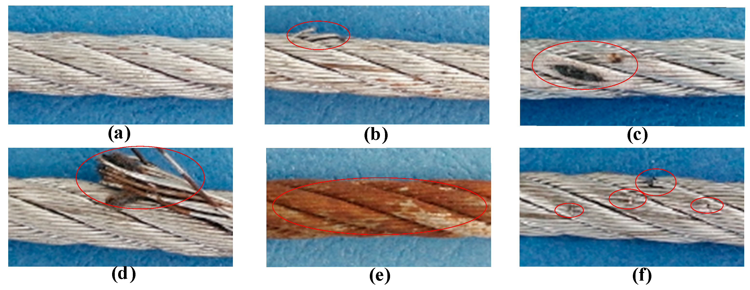
In this part, through processing and fusing magnetic signal and infrared image, the classification for six kinds of broken wires is implemented. In this experiment, the number of broken wires is one, two, three, four, five, and seven. Many wires are wound into a strand, then it is wounded into a wire rope. The damage of the wire rope is related to the geometry and winding mode of the wire rope [1, 2, 13]. As shown in Figure 1, the structure of the wire rope is with a diameter of 28 mm. The length of the wire ropes is 6.5 m. The specimens used are 185, where the number of training samples is 139 and testing number is 46. The number of broken wires is from 1 to 5 and 7 wires, where the number of every samples set of broken wires is 30, 30, 32, 34, 35, and 34. The width of samples contains 2 mm, 5 mm, and 1.5 cm. The depth of defects is 1 mm. The type of defect is shown in Figure 2.
When there is no defect on wire rope and materials of the wire rope are uniform and identical, the magnetic flux through the cross-section of the wire rope should be equal in the axial direction. If there is a defect, the permeability at the defect becomes smaller, the magnetic field only passes through the air field and then returns to the inside of the wire rope; thus, magnetic leakage on surface is formed [12–14]. According to this principle, a magnetic flux leakage detection device is designed. Data collection contains magnetic signal acquisition and thermal infrared image acquisition. The specific devices and collecting procedures are as follows: the magnetic data acquisition device adopted contains Unsaturated Magnetic Excitation (UME) source, an array of 18 Giant Magnetoresistance (GMR) sensors, data acquisition unit, data storage, and control system [33].
As shown in Figure 4, data collection steps are as follows: After loading unsaturated magnetic field on wire rope, the weak MFL signal can be obtained through equal-space sampling. As the acquisition system moves along the axial direction of the wire rope, the photoelectric encoder produces the pulses. Then, the control system collects the defect information from 18 channels according to pulses. And the final magnetic data is stored in the SD card.
Because the rate of infrared radiation from defect location is different from that from nondefect location, the damage of wire rope can be detected. Infrared information acquisition system, as shown in Figure 5(a), includes heating unit and data collection. The heating unit is composed of the metal tube and tight wires. The metal tube is 40 mm in diameter and 20 cm in length. Wire is adopted to heat the metal tube. Infrared thermography is adopted to capture the images of defect information. The angle of camera should be adjusted according to the location of the defects to maintain the distance between the defect and the camera lens constant. The camera we adopted is thermal imager FLUKE TIX 660. The thermal resolution of the infrared camera is -20°C-1200°C. The distance between wire rope and camera is cm. The specific processes are as follows: after the wire is energized, the wire rope temperature rises by heating the metal tube. When the temperature of fault is maintained at about (°C), the defect images are taken by the infrared camera. Single images are acquired through the device shown in Figure 5(a). After installing the thermal infrared camera on the tripod, the defective part is heated, and the images of wire rope surface defect are obtained by panning the tripod. The focus of the image is formed by centering the defect and fixing the distance between the defect and the camera. The captured raw infrared picture is shown in Figure 5(b). (The defect is marked by a box.)
Infrared image acquisition: (a) schematic of infrared data acquisition device; (b) the raw infrared picture of defect; (c) thermal infrared image capture system; (d) testing platform for wire rope.
Using the system mentioned in Figure 4, raw UME signals can be obtained. As shown in Figure 6. Raw UME signals including incoherent baseline caused by channel imbalance, system noise, and strand wave noise produced by structure of wire rope should be filtered out to obtain pure defects information.
To eliminate the effect of uneven excitation on wire ropes and convert all the data with a uniform standard, normalization is necessary. Normalization is the basis of data visualization; hence, equation (18) is adopted to stretch the defects between 0–255.
Because circumferential data is acquired from 18 sensor channels, circumferential resolution is much lower than the axial one. The pixel count in circumferential is 18; however, the pixel count in axial is more than ten thousand. Three spline interpolations is employed to enhance the circumferential resolution, which increases the pixel count from 18 to 300. In addition, the procedure contributes to realize the visualization of defect images. The schematic of data after interpolations is shown in Figure 10. Then, we obtain gray image of leakage magnetic by converting the double data to unit 8. Figure 11 shows the grayscale image of a wire rope’s leakage magnetic field.
The image after texture filtering also exists strand wave, which makes trouble for feature extraction. The distances between strand waves are fixed according to the structure of wire rope, and the defects are located between strand waves. Therefore, an algorithm based on distance is proposed to part the damage. The algorithm can be described as follows:
(1)After binarization of image , locate the maximum and minimum values of the row and column with pixel value of 1 in the image, respectively. Then the image , as shown in Figure 13, is obtained: ( and are the maximum and minimum of line; and are the maximum and minimum of column).(2)For each line of image, find and :(3)Compute the distances for blocks whose pixel value is 1 by(4)For each line of the image , if the distance is between 10 and 70 and the block is larger than 12 (which can avoid the effect of oil pollution), maintain the line or set the line to zero. (The distance of two strands in wire rope is consist and strand wave shown in the image is also consist. Meanwhile, in order to reduce the effect of oil pollution on the segmentation defect, we choose the distance between 10 and 70 and the block larger than 12.)(5)Extract the defects of infrared images by finding the locations from that meet (4).
Image of broken wires (infrared image, magnetic image, and photo of the tested wire part from left to right): (a) one broken wire; (b) two broken wires; (c) three broken wires; (d) four broken wires; (e) five broken wires; (f) seven broken wires.
The defect images from UME and infrared have high dimension, which will reduce the speed of classification. Redundancy between features can also be disastrous for networks. Thus, it is necessary to employ proper features to implement recognition. Tan and Zhang [33] had proven that average contrast, third-order moment, conformance, and entropy were more sensitive than other texture features and odd order invariant moments were more sensitive than other moments. Thus, in this experiment, a part of statistical texture features and odd order invariant moments from the magnetic images and the color moments and areas from the infrared images are selected.
When completing classification via magnetic features only, a part of statistical texture features and odd order invariant moments is adopted. If the magnetic and infrared information are combined to classify the broken wires, we added the color moments and area of infrared images as features.3.3.2. Fusion Based on KELM
Infrared data is closer to the actual damage pattern than magnetic data and provides more color information; however, different sizes of same broken wires may lead to low accuracy. Magnetic data with the same broken wires has similar visual image. Thus, the combination of the two methods can supply more information for the damage and improve the classification accuracy.
Through Table 1, it is demonstrated that as the number of test samples increases, the quality of the results gets better. When selecting model 2 to present the speed of classifiers, the result of fusion speed is as shown in Table 2. In Table 1, the fusion results of RBF and KELM are better than BP and KNN. Meanwhile, fusion speed of KELM shown in Table 2 is the best. Thus, through analyzing the result in Tables 1 and 2, it is obvious that KELM is reliable. The research for the performance of recognition algorithms and classification results will be presented in the next section.
In this part, the classification results are presented using different recognition algorithms. KELM has advantages of high running speed and good generalization, we adopted it to implement the recognition of 6 classes of broken wires. In this section, the defects by magnetic information, infrared data, and combination of the magnetic and infrared information are classified, respectively, which proves that the information fusion is more effective. For KELM, the penalty coefficient C and kernel parameter are adjusted from the set and . The KELM network is trained by a set of 139 randomly selected specimens, and the others are the testing samples.
For UME, the average of two error accuracy of 20 random train/test splits with different parameters are reported in Table 3. Different parameters will lead to different identification accuracy. When and , the recognition accuracy rate is the highest; however, the average training accuracy is only 82.3%. The average training accuracy reaches 96.7% and the recognition accuracy is 91.2% when and . Table 3 presents the average of two error recognition accuracy of 20 randomly generated train/test splits based on the fusion of magnetic and infrared. When the training accuracy is higher than 90%, the highest accuracy is 98.4%.
Figure 17 shows the absolute error distribution of one group testing result when and . The training accuracy of two methods are all higher than 90%. When the magnetic information only exists in the network, the maximum error is 5. When the infrared information only exists in the network, the maximum error is also 5. And the most errors are concentrated in one and two broken wires. However, when the fusion features contain in the network, the maximum error is 2, and the recognition accuracy is higher. It is obvious that there are fewer errors using the fused features than that adopting magnetic features only and infrared only. Therefore, these testing results demonstrate that the fusion of magnetic and infrared not only is feasible but also can improve the recognition accuracy of broken wires.
Several recognition algorithms are applied to the MFL data: BP neural network [28, 29, 32], RBF algorithm [27], and KNN algorithm [30]. The data for recognition is the same as that used in the KELM network. Tables 4–6 show the recognition results for each method when the limiting error is 2 wires.
From Tables 3–6, it is obvious that the fused data yielded much better classification results than magnetic data. In this paper, neural networks are considered reliable when the training accuracy is higher than 90%. (Note that KNN has no training process and the algorithm finds samples in the training set closest to the test sample based on a distance measurement [30, 45].) Therefore, the highest recognition rates are presented in Table 7. Table 7 presents the best results of four classifiers using only magnetic data, infrared data, and fused data. It is obvious that the result for fused data is higher than magnetic and infrared.
The research promotes recognition rate of broken wires and makes contributions to estimating the residual lifetime of wire rope. The two information can overcome the loss of small defects in magnetic signal noise reduction. The system we utilized have good performance facing the defects at the exterior of the rope. However, the thermal infrared acquisition system needs to be perfected to realize the image information acquisition of the whole wire rope. Furthermore, we have not been able to create defects inside of the wire rope. We will simulate the situation when the defect is inside the wire rope through analysis in future work. Meanwhile, efficient noise reduction algorithm is also one of the focuses of future research.

Ropes made from high modulus polyethylene (HMPE) have superior tension fatigue properties compared to ropes made from steel wire or other synthetic fibers (i.e. nylon, polyester, aramids, etc.), as shown in Table 1.
The testing summarized in this document is focused on HMPE-based ropes. The test included two samples of each rope type from three different manufactures, referred to here as AmSteel®-Blue and Saturn-12 (both Samson products), Product C, and Product D (from 2 different domestic manufacturers). All samples were 12-strand single braids, 3/8” (9 mm) nominal diameter, made from HMPE fiber (Samson AmSteel®-Blue and Saturn-12 are 100% Dyneema® HMPE fiber, Product C and D are 100% Spectra® HMPE fiber). Product D uses heat setting in post processing while Product C uses construction design characteristics that optimize break strength and keep stretch low. Samson’s two products use a balanced construction that strives to achieve high strength and low stretch while maximizing fatigue life and abrasion resistance.
The effects of heat setting on HMPE rope is well documented (see Samson Technical Bulletin: HMPE Rope—Effects of Post Production Processes). HMPE ropes characteristically show an initial increase in strength as they are worked for the first 40% of their expected tension fatigue lifetime. Heat setting pushes the rope along the expected strength curve to the maximum strength the fiber will be expected to achieve before it is placed in service. The strength gain comes at the price of a significantly reduced fatigue lifetime.
The rope’s construction design—twist levels and braid angles—also influences both strength, fatigue life and resistance to abrasion. (See Samson Technical Bulletin: HMPE Rope: Design vs. Performance). High strength can be achieved using a longer cycle length that results in a looser braid. Testing shows that it also results in lower tension fatigue resistance and lower abrasion resistance
ice evaluation of amusement park rides, bridges, cranes, ship loaders and may other load bearing assets. This article briefly introduces the various wire rope testing methods and their respective advantages and disadvantages. The basic wire rope testing methods are visual wire rope testing, magnetic flux leakage (MFL) wire rope testing, long range ultrasonic testing (LRUT) and acoustic emission testing of steel cables.
Visual wire rope is a fast and economical non-destructive testing technique that detects wire breaks on the outside diameter of the wire rope. Wire rope testing is commonly performed using a cloth rag lightly wrapped the rope that catches on protruding wires. Visual wire rope testing is performed routinely across all industries. Visual inspection cannot determine condition under collars, seizing wires, separators, sockets and gatherers since due to accessibility. In addition to wire breaks, this method can detect reductions in diameter, corrosion, birdcage, waviness, kinks and deformations.
Some disadvantages include disadvantages include that it cannot detect corrosion/breaks on the interior strands and under paint. Impossible to size subsurface defects.
MFL testing of wire rope and steel cables introduces a magnetic field along the primary axis of the wire rope using magnetizing measurement head. Wire breaks cause a disruption in the magnetic field causing it to leak out from the rope. The magnetic flux leakage (MFL) is detected by a Hall sensor in the measuring head. The measuring head is generally equipped with an encoder wheel to accurately track wire break locations.
MFL wire rope testing is most practical and economical on moving ropes since a winching system is not required to pull the measuring head. Additionally, the maximum rope diameter that can be MFL tested is approximately 4”. Lastly, specialized measuring heads, at extra cost, may be required for groups of wire ropes with minimum clearance. Consider that each measuring head has certain size and must small enough to mount in the clearance area between the ropes. Example MFL wire rope testing data is shown in Figure 2. The wire rope testing data are presented as milli-voltage (mV) versus distance correlated to the encoder wheel. The measured mV on the vertical axis is proportional to the magnetic flux leakage caused by wire rope breaks. The upper data (OUT) reports on wire rope testing of the outer strands of the cable. The middle data (INN) reports on wire rope testing of the inner strands of the cable. The bottom (blue) wire rope testing data records loss of metallic area (LMA) during the wire rope inspection.
MFL wire rope testing is performed on ropes in the 0.50 to 4.00” diameter range. Moving rope like those used on amusement park rides, ski-lifts, elevators, and lifting devices are easily tested with and MFL measuring head and encoder wheel. MFL wire rope testing is often performed on standing ropes like those found on ship loaders and bridge stay cables, however, these applications are slightly more complicated, time consuming, and expensive due to a winching requirement.
TKS specializes in the monitoring of suspender cables and ropes in cable-stay and suspension bridges, using acoustic emission (AE) for wire breaks. This technology is recommended for larger diameter ropes and cables that may not be suitable for MFL wire rope testing or long-range ultrasound testing (LRUT), also known as guided wave ultrasonic testing (GWUT). Bridge cable inspection using acoustic emission technology has been utilized to provide risk-based inspection and maintenance for fracture critical members in infrastructure such as bridges and storage tanks. The technology provides real-time feedback on structural condition without the need for direct access to the area of interest.
Acoustic emission in bridge cable is produced by wire breaks, strand breaks, corrosion related events that may be correlated to individual strand deterioration, or group of strand deterioration, and other mechanisms. Bridge cable acoustic emission data is analyzed for both intensity and rate at which it is generated. Acoustic emission intensity is analyzed by considering acoustic emission amplitude, acoustic emission energy, and acoustic emission counts. The rate at which acoustic emission is emitted is analyzed to determine if deterioration is progressing. No acoustic emission activity implies that no active AE source was present during the duration of the test. Acoustic emission rates may also be categorized as stable, increasing linearly, and exponentially.
Follow-up visual inspections are recommended based on inspection results. Cable rubbing or fretting at gatherers, collars, separators and sockets generate acoustic emission which may be confused with acoustic emission generated from wire breaks. Broader disadvantages include that multiple sensors are require per cable with significant installation setup time. No defect sizing is possible.
Long range ultrasound (LRUT), or guided wave ultrasonic testing (GWUT), is used as a screening tool for oil and natural gas pipelines, bridge pile, and railroad track. The technology provides real-time feedback on structural condition without the need for direct access to the area of interest. Cable inspection typically takes about 20 minutes. The sensor is installed on bottom end of cable with a low frequency ultrasonic wave transmitted from the sensor to top end of cable – typically the main cable. Similarly a guided wave is transmitted downwards to the suspender rope socket. Ultrasound is reflected back from wire breaks and other cable defects and cable defects are identified by location and severity: minor, moderate and advanced. Follow-up visual inspections are recommended based on inspection results.
Figure 4. Example long range ultrasonic testing bridge cable data showing cable socket, intersection with main cable at 110 feet and corrosion at 85 feet.
Chant Engineering manufactures a variety of test beds and options. Our standard pull test machines are available in a horizontal or vertical layout. We also offer mobile test beds, break test, pre-stretch and tugger winch testing machines.
Chant Proof Test Machines are rugged and proven to stand up to the test. Test beds are designed to take your products to their maximum limit for both non-destructive and destructive testing. Chant Testing Machines will proof test your products for load, torque and breaking points in your own test environment. Chant fully understands your product testing needs and has a full line of standard test beds. We can also engineer and manufacture any proof test machine you can dream through complete customization.
Did you know that Chant now offers leasing options for its test beds? You can now lease a proof test machine for as low as $2,000/month. We have 2, 3, 4, and 5 year lease options available. Start a new revenue stream for your rigging shop today! Give us a call for a quote and leasing terms. How can you afford not to?
You know that your parts require some kind of non-destructive testing inspection, but do you know what is happening to your parts when that test method is applied? Over the next few weeks, our level III technicians will provide an explanation of each NDT method we employ along with some advantages and limitations of each.
The equipment utilizes two strong magnets in a clam shell type set up to clamp around the rope. These magnets create a constant magnetic field in the steel rope. Since the magnetic field is constant, the amount of flux necessary to saturate the rope is a function of the cross-sectional area of the rope.
If the section of the rope that passes through the machine contains defects such as broken wires, corrosion thinning or stretching, the magnetic flux will be affected. These changes are interpreted on an oscilloscope display.
With proper calibration and training the technician can determine percentage of cross sectional loss, broken wires, and overall loss of break strength.


 8613371530291