
wire rope breaking strength calculation free sample
Wire rope is also known by many other names, such as: wire, multi-strand wire, flexible wire, cable, cord, steelcord, etc. but it is essentially a collection of small filaments wound around each other in a manner that largely retains its shape when bent, crushed and/or tensioned.
It is a system for significantly increasing the strength and flexibility of steel wire and is used in almost every important application we see around us. For example: suspension bridges, tyres, brake and accelerator cables (in cars), high-pressure flexible pipes, lifting and rigging cables, electrical conductors, etc. and it comes in many different forms. Fig 2 shows just a very small sample of available designs.
With minor variations, the generally accepted method for designating a wire rope construction in the industry is by describing it numerically. For example:
Whilst "IWRC" wire ropes offer a slightly greater tensile capacity (≈7%) than those with fabric or polymer fillers, the additional strength does not come from the tensile capacity of the core filaments but from improved dimensional stability under load. And whilst they are also much more resistant to crushing, they are stiffer than fibre core ropes and therefore not recommended for applications where tension occurs under bending.
Warrington (Fig 1) is a parallel lay construction with an outer layer comprising wires of alternating large and small diameters, each outer layer having twice the number of wires as the layer immediately beneath. The benefit of this design is to increase packing and therefore strength density, however, unless the different diameter filaments are of the same strength (unlikely), this construction is limited by the strength of the weakest filaments.
Seale (Figs 1 & 2 6x36) is also a parallel lay construction but with the same number of wires in each wire layer. All the wires in any layer are the same diameter. This is an alternative to the Warrington construction, with similar benefits and disadvantages.
Regular lay constructions are used much more widely (than Lang lay) because they have excellent structural stability and less tendency to unwrap under tension (see Rotating vs Non-Rotating below). However, because it has a knobbly (undulating) surface it will wear both itself and any surface over which it is run much more quickly than Lang lay wire rope.
Lang lay constructions have a flatter surface than regular lay constructions giving them better resistance to wear and bending fatigue, especially when made from flattened (elliptical) filaments. They are, however, much less structurally stable and subject to birdcaging if the wire rope is over-bent or twisted against its wrapped direction.
"Regular Lay", multi-strand constructions are normally subject to slightly less rotation under tension (than Lang lay) due to the opposite helical direction of the filaments (within the strands) and the strands (within the rope), however, you can improve their rotation characteristics still further by;
Fillers (Fig 2) may be fabric, polymer or even smaller diameter filaments (e.g. 6x36). Whilst they contribute little to the tensile strength of wire rope, they can significantly; improve performance under bending (fabric and polymer cores only), reduce axial growth, reduce rotation in rotation-resistant constructions, improve structural stability and increase fatigue life.
This filler material should not be included in strength (tensile capacity) calculations, but must be included in those for axial stiffness (extension). If it is ignored, your calculations will reveal excessive extension as the wire rope collapses.
Suspension bridges tend to be constructed from densely packed, single strand plain "Wire Rope" constructions using large diameter galvanised filaments. Little heed is paid to rotational resistance as strength is paramount and once tensioned, they should remain in that loading condition for their design life.
Lifting & winching normally require wire ropes of good flexibility and fatigue resistance. Therefore they tend to be similar to 6x36 but with fibre core instead of the IWRC in Fig 2
Hosecord is suitable for HPHT flexible pipes as lateral flexibility is generally considered less important than minimal longitudinal growth or maximum tensile strength (per unit cross-sectional area).
Remote operating cables such as hand-brakes and accelerators on cars normally only work in tension so they need to be strong but not necessarily stiff (as they are fully contained in reinforced outer sheaths). These tend to be manufactured from large diameter "TyreCord" or small diameter single-strand "Wire Rope".
Wire rope does not obey Hooke"s law. Therefore, you cannot accurately predict how much it will stretch for any specified force. This unpredictability applies to any section removed from the same manufactured length of cord and even between cords produced to the same specification but by different manufacturers.
CalQlata has decided that the accuracy of axial stiffness (EA) of wire rope falls outside its own levels of acceptability and therefore does not include it in the wire rope calculator. The extension calculated in the Wire Rope calculator (δLᵀ) is based upon the effect of axial tension on packing density. It is therefore important that core material is not ignored when using the calculator to evaluate this characteristic.
Wire rope does not obey Hooke"s law. Therefore, you cannot accurately predict how much it will twist for any specified torque. This unpredictability applies to any section removed from the same manufactured length of cord and even between cords produced to the same specification but by different manufacturers.
CalQlata has decided that the accuracy of torsional stiffness (GJ) of wire rope falls outside its own levels of acceptability and therefore does not include it in the wire rope calculator.
1) No wire rope calculator, whether dedicated or generic, will accurately predict the properties of any single construction under a wide range of loading conditions
2) No wire rope calculator, whether dedicated or generic, will accurately predict any single property for a range of constructions under a wide range of loading conditions
The only wire rope that can be reliably analysed is that which is used for suspension bridges, because; it comprises a single strand, is very densely packed, has negligible twist, contains filaments of only one diameter, is never subjected to minimum bending and every filament is individually tensioned.
There is a very good reason why manufacturers do not present calculated performance data for construction or design proposals, because even they cannot accurately predict such properties and quite rightly rely on, and publish, test data.
During his time working in the industry, the wire rope calculator"s creator has seen, created and abandoned numerous mathematical models both simple and complex. He has gradually developed his own simplified calculation principle based upon his own experience that still provides him with consistently reliable results of reasonable accuracy.
The purpose of CalQlata"s wire rope calculator is to provide its user with the ability to obtain a reasonable approximation for a generic construction, after which, accurate test data should be sought from the manufacturer for the user"s preferred construction.
The calculation principle in the wire rope calculator is based upon changes in the properties of the wire rope that occur with variations in packing density under tension
Bearing in mind the above limitations CalQlata can provide the following assistance when generating (manipulating) the wire rope calculator"s input data and interpreting its output
Alternatively, for wire rope with multiple filament diameters, you need to find an equivalent diameter with the following proviso; you must enter the minimum filament yield stress (SMYS)
It is expected that apart from fillers, all the material in the wire rope will be identical and therefore have the same density, i.e. using different materials will result in less than "best" performance. However, if such a construction is proposed, you can calculate an equivalent density as follows:
It is expected that apart from fillers, all the material in the wire rope will be identical and therefore have the same tensile modulus, i.e. using different materials will result in less than "best" performance. However, if such a construction is proposed, you should enter the highest tensile modulus.
The wire rope calculator simply adds together the total area of all the filaments and multiplies them by the SMYS entered, which represents a theoretical maximum breaking load that would exist if this load is equally shared across all of the filaments and the lay angles have been arranged to eliminate localised (point) loads between adjacent filaments.
If the wire rope has been properly constructed it is likely that its actual break load will be greater than 80% of this theoretical value. However, given the vagaries of wire rope construction, the actual break load can vary considerably dependent upon a number of factors. CalQlata suggest that the following factors may be used to define the anticipated break load of any given construction:
The axial stiffness and strain under load will be affected by this value, hence the reason why the most reliable (predictable) constructions tend to be minimum [number of] strands and single filament diameter. The Warrington and Seale constructions and combinations thereof tend to provide the highest packing density (but lowest flexibility) and there is little to be gained from using these constructions in more than single stranded wire rope as the benefit of high-packing density will be lost with no gain in flexibility.
The anticipated second moment of area of the wire rope at tension "T" due to deformation but insignificant flattening as it is assumed the wire rope will be bent over a formed (shaped) sheave or roller.
The anticipated tensile modulus of the wire rope at tension "T" due to deformation but insignificant flattening as it is assumed the wire rope will be bent over a formed (shaped) sheave or roller.
It is not advisable to induce this bend radius in operation due to uncertainties associated with wire rope construction, especially for dynamic applications. CalQlata suggests that a similar approach to that used for the break load (Fb) above also be applied here, i.e.:
A change in diameter will occur in all wire rope, irrespective of construction, until packing density has reached a limiting value. The value provided in the wire rope calculator is that which would be expected if the construction remains intact at the applied tension "T"
Unreliability of this value increases with complexity in wire rope due to its longitudinal variability and the increased likelihood of premature failure.
The accuracy of this data will range from about ±1% for wire rope with a single strand and a single filament diameter, up to about ±15% for constructions of similar complexity to OTR cord
A change in length of any wire rope will occur due to the fact that the packing density increases with tension. This is not, however, a linear relationship.
This can be an unreliable value as illustrated by tests carried out (by the author) on two pieces of wire rope supplied by the same well-known manufacturer both of which were cut from the same length, varied in tensile capacity by only 1.5%, but the tensile modulus (and strain at break) varied by 34%. Whilst this was an extreme case, significant variations have been seen in wire rope manufactured by a number of manufacturers.
Whilst the wire rope calculator does not calculate axial stiffness (see Calculation Limitations 9) above), CalQlata can suggest the following rule-of-thumb that will provide reasonable results for most constructions at the applied tension "T":
Whilst the wire rope calculator does not calculate bending stiffness (see Calculation Limitations 8) above), CalQlata can suggest the following rule-of-thumb that will provide reasonable results for most constructions at the applied tension "T":
Low complexity means single strand and single wire diameter. Medium complexity means multi-strand and single wire diameter. High complexity means multi-strand and multiple wire diameters.

Wire ropes are largely used in marine environment or for rigging purposes. They receive considerable loads and thus suffer a great deal of mechanical damage throughout their service life. Moreover, research has shown that the major cause of wire rope failure is excessive deterioration and corrosion, lack of maintenance and inspection, and wrong usage resulting in early discarding, reduced safety and replacement cost increase.
Sometimes damage can be easily detected, while in other cases fractured wires may occur on the inside. Hence, wire ropes should be inspected and maintained by the right person (competent person assigned by the company), to assure they’re in perfect condition. Regular inspectionsensure high rope performance, long service lifetime , safety of personnel and equipment, and reduced operating costs.
All ropes (synthetic, high modulus and wire ropes) should be inspected before and after an operation. This guideline ensures maximum safety for both a ship’s personnel and equipment. Even though it’s difficult to determine the exact service life span of ropes, there is a way to have a more precise estimation about their efficient lifecycle. Calculating the exact time ropes have been in use (e.g mooring time, mooring conditions, weather and tidal conditions) is the answer. All in all, rope inspections should occur at least once a year.
Inspecting wire ropes in particular, comes with great responsibility. Inspection results should be recorded, and any defects noticed have to be reported and addressed properly. Some defects can be repaired, while in some cases replacing a wire rope is inevitable.
Periodical inspections ofvessel deck equipment is also crucial for maintaining the good condition of wire ropes. The condition of the drum, chocks, bitts, rollers, sheaves, cable clamps and other end fittings, affect the rope’s performance, threads and cords. Make sure to mark these parts during your overall inspection.
In order to help marine officers and staff conduct successful wire rope inspections – and keep an up-to-date record of them – we have created an inspection solution that helps in maintaining and monitoring a ship’s ropes and deck equipment.Learn more about Katradis inspection Neptune Solution
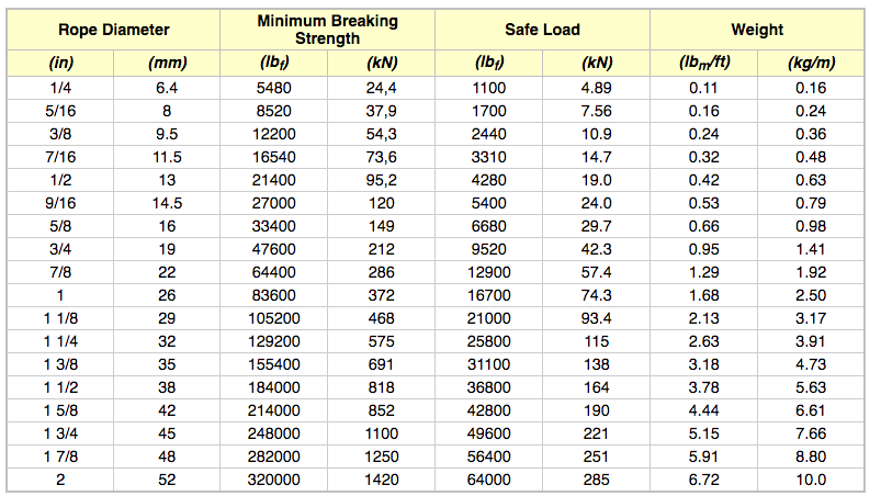
When calculating mass using F = Minimum Breaking Force, according to the wire rope’s diameter, you can determine the Minimum Breaking Massand therefore the wire’s max strength. When calculating mass using F = Safe Load according to the wire rope’s diameter, you can determine the Safe Load Mass,which is the advised load for this rope diameter.
The strands of a wire rope absorb the majority of the tensile force applied on the rope. Their design and manufacturing standards affect the level of fatigue resistance and resistance to abrasion. An easy way to understand which rope design is suitable for each purpose, is the wire rope classification.
Wire ropes are classified according to the number of strands in each construction and the number of wires in each strand. For example, a classification of 6X19 means that a wire rope of this type always has six strands, but its wires could be 15-26 per strand. This is because 19 is not the exact number of wires, but the classification of a wire number range.
Visual inspections are a common and fast way to assess wire rope condition. Both the standard and rotation resistant wire rope inspectionprocesscomply with the same four steps of examination. A ship’s crew can perform them as follows:
Steel wire rope distortion is obvious in most cases and can easily be identified by the inspector or the ship‘s crew. It usually occurs if load is suddenly applied or abruptly released (shock loading), or even if swift torque is forcefully induced.
Although not all of these deformations make the rope absolutely dangerous to use, they all may cause ropes to wear unevenly in time. This means inspections should take place more often, and distorted ropes should be handled with caution.
The rag and visual inspection is a good method for regular inspection intervals. The inspector pulls a rag along the rope trying to find broken wire cords. If the rug gets snagged by the rope, the inspector has to stop and assess the wire rope’s condition. Extreme caution should be exercised during the visual inspection, and under no circumstances should this method be the only one used to inspect wire ropes.
Tip: When you encounter a protruding wire end, bend it back and forth manually, until it separates from the wire. This will protect neighboring wires from wearing out.
Diameter reduction is a critical factor in steel wire rope wear and if not properly taken care of, it can result in rope breakage. Excessive abrasion, loss of core mass, corrosion or inner wire failure are all factors that contribute to diameter reduction.
To get an accurate measurement of the rope’s diameter, measure the rope at three different points at least 5 feet apart. Take the average of these three measurements to determine the true diameter.
Any measurements showing a reduction of ⅓ or more, indicate that a replacement should follow without delay. A diameter reduction of less than 1/3 still requires attention, and the inspector or the ship’s crew should be on guard in the next scheduled wire rope inspection.
Failure from abrasion or corrosion is a result of deficient deck equipment inspection or insufficient wire rope lubrication respectively. Internal corrosive damage is more difficult to identify than any other types of degradation. In most cases, the damage has progressed more than the external signs suggest.
Wire rope storage plays a significant role in the rope’s operation life.Wire rope corrosion and pitting can be avoided if ropes are safely stored in a clean, cool, dry and well-ventilated place. Steel wire ropes should not by any means rest on the floor, and should be protected from water, dust or any chemical fumes. Long term storage requires periodic greasing, turning the reel upside down for preventing grease dripping and possibly re-winding to another reel with larger inner tube diameter.
Wire ropes should be maintained with periodical lubrication. In order to prevent internal corrosion, a pressure lubricator is suggested to be used. In this case, a small amount of grease is used to lubricate the rope internally, while the deck stays grease-clean. Pressure lubricators clean the rope before they grease it so that the new grease enters a clean rope. The type of grease used is very important for maximum protection and greasing efficiency.
Steel wire ropes exposed to dirt, grime and other contaminants, have to be cleaned with a wire brush and petroleum (unless a pressure lubricator is used). Optimal cleaning of wire ropes can extend their service life and guarantee safe operations.
The reeling process is of high importance for the longevity of wire ropes. To protect them from being damaged, it is important that the surface of the drum is clean, smooth and dry. Improper reeling may cause wire-rope strands to spread or get flattened, when in contact with one another, as successive layers are being spooled and upper layers apply pressure on the lower ones.
Katradis S.A. offers a wide range of top quality wire ropes for shipping (mooring and hoisting operations), fishing and construction purposes. Our wire ropes have greater resistance to fatigue, and they distribute tension force equally among the rope strands. They are less likely to kink, providing higher staff safety and assuring operation success.Choose your new wire ropes

Rope strength is a misunderstood metric. One boater will talk about tensile strength, while the other will talk about working load. Both of these are important measurements, and it’s worth learning how to measure and understand them. Each of these measurements has different uses, and here we’re going to give a brief overview of what’s what. Here’s all you need to know about rope strength.
Each type of line, natural fiber, synthetic and wire rope, have different breaking strengths and safe working loads. Natural breaking strength of manila line is the standard against which other lines are compared. Synthetic lines have been assigned “comparison factors” against which they are compared to manila line. The basic breaking strength factor for manila line is found by multiplying the square of the circumference of the line by 900 lbs.
As an example, if you had a piece of ½” manila line and wanted to find the breaking strength, you would first calculate the circumference. (.5 X 3.14 = 1.57) Then using the formula above:
To calculate the breaking strength of synthetic lines you need to add one more factor. As mentioned above, a comparison factor has been developed to compare the breaking strength of synthetics over manila. Since synthetics are stronger than manila an additional multiplication step is added to the formula above.
Using the example above, letÂ’s find the breaking strength of a piece of ½” nylon line. First, convert the diameter to the circumference as we did above and then write the formula including the extra comparison factor step.
Knots and splices will reduce the breaking strength of a line by as much as 50 to 60 percent. The weakest point in the line is the knot or slice. However, a splice is stronger than a knot.
Just being able to calculate breaking strength doesn’t give one a safety margin. The breaking strength formula was developed on the average breaking strength of a new line under laboratory conditions. Without straining the line until it parts, you don’t know if that particular piece of line was above average or below average. For more information, we have discussed the safe working load of ropes made of different materials in this article here.
It’s very important to understand the fundamental differences between the tensile strength of a rope, and a rope’s working load. Both terms refer to rope strength but they’re not the same measurement.
A rope’s tensile strength is the measure of a brand-new rope’s breaking point tested under strict laboratory-controlled conditions. These tests are done by incrementally increasing the load that a rope is expected to carry, until the rope breaks. Rather than adding weight to a line, the test is performed by wrapping the rope around two capstans that slowly turn the rope, adding increasing tension until the rope fails. This test will be repeated on numerous ropes, and an average will be taken. Note that all of these tests will use the ASTM test method D-6268.
The average number will be quoted as the rope’s tensile strength. However, a manufacturer may also test a rope’s minimum tensile strength. This number is often used instead. A rope’s minimum tensile strength is calculated in the same way, but it takes the average strength rating and reduces it by 20%.
A rope’s working load is a different measurement altogether. It’s determined by taking the tensile strength rating and dividing it accordingly, making a figure that’s more in-line with an appropriate maximum load, taking factors such as construction, weave, and rope longevity into the mix as well. A large number of variables will determine the maximum working load of a rope, including the age and condition of the rope too. It’s a complicated equation (as demonstrated above) and if math isn’t your strong point, it’s best left to professionals.
However, if you want to make an educated guess at the recommended working load of a rope, it usually falls between 15% and 25% of the line’s tensile strength rating. It’s a lotlower than you’d think. There are some exceptions, and different construction methods yield different results. For example, a Nylon rope braided with certain fibers may have a stronger working load than a rope twisted out of natural fibers.
For safety purposes, always refer to the information issued by your rope’s manufacturer, and pay close attention to the working load and don’t exceed it. Safety first! Always.
If you’re a regular sailor, climber, or arborist, or just have a keen interest in knot-tying, be warned! Every knot that you tie will reduce your rope’s overall tensile strength. Some knots aren’t particularly damaging, while others can be devastating. A good rule of thumb is to accept the fact that a tied knot will reduce your rope’s tensile strength by around 50%. That’s an extreme figure, sure, but when it comes to hauling critical loads, why take chances?
Knots are unavoidable: they’re useful, practical, and strong. Splices are the same. They both degrade a rope’s strength. They do this because a slight distortion of a rope will cause certain parts of the rope (namely the outer strands) to carry more weight than others (the inner strand). In some cases, the outer strands end up carrying all the weight while the inner strands carry none of it! This isn’t ideal, as you can imagine.
Some knots cause certain fibers to become compressed, and others stretched. When combined together, all of these issues can have a substantial effect on a rope’s ability to carry loads.
Naturally, it’s not always as drastic as strength loss of 50% or more. Some knots aren’t that damaging, some loads aren’t significant enough to cause stress, and some rope materials, such as polypropylene, Dyneema, and other modern fibers, are more resilient than others. Just keep in mind that any knots or splices will reduce your rope’s operations life span. And that’s before we talk about other factors such as the weather or your rope care regime…
Wire ropes are essential for safety purposes on construction sites and industrial workplaces. They are used to secure and transport extremely heavy pieces of equipment – so they must be strong enough to withstand substantial loads. This is why the wire rope safety factor is crucial.
You may have heard that it is always recommended to use wire ropes or slings with a higher breaking strength than the actual load. For instance, say that you need to move 50,000 lbs. with an overhead crane. You should generally use equipment with a working load limit that is rated for weight at least five times higher – or 250,000 lbs. in this case.
This recommendation is all thanks to the wire rope safety factor. This calculation is designed to help you determine important numbers, such as the minimum breaking strength and the working load limit of a wire rope.
The safety factor is a measurement of how strong of a force a wire rope can withstand before it breaks. It is commonly stated as a ratio, such as 5:1. This means that the wire rope can hold five times their Safe Work Load (SWL) before it will break.
So, if a 5:1 wire rope’s SWL is 10,000 lbs., the safety factor is 50,000 lbs. However, you would never want to place a load near 50,000 lbs. for wire rope safety reasons.
The safety factor rating of a wire rope is the calculation of the Minimum Break Strength (MBS) or the Minimum Breaking Load (MBL) compared to the highest absolute maximum load limit. It is crucial to use a wire rope with a high ratio to account for factors that could influence the weight of the load.
The Safe Working Load (SWL) is a measurement that is required by law to be clearly marked on all lifting devices – including hoists, lifting machines, and tackles. However, this is not visibly listed on wire ropes, so it is important to understand what this term means and how to calculate it.
The safe working load will change depending on the diameter of the wire rope and its weight per foot. Of course, the smaller the wire rope is, the lower its SWL will be. The SWL also changes depending on the safety factor ratio.
The margin of safety for wire ropes accounts for any unexpected extra loads to ensure the utmost safety for everyone involved. Every year there aredue to overhead crane accidents. Many of these deaths occur when a heavy load is dropped because the weight load limit was not properly calculated and the wire rope broke or slipped.
The margin of safety is a hazard control calculation that essentially accounts for worst-case scenarios. For instance, what if a strong gust of wind were to blow while a crane was lifting a load? Or what if the brakes slipped and the load dropped several feet unexpectedly? This is certainly a wire rope safety factor that must be considered.
Themargin of safety(also referred to as the factor of safety) measures the ultimate load or stress divided by theallowablestress. This helps to account for the applied tensile forces and stress thatcouldbe applied to the rope, causing it to inch closer to the breaking strength limit.
A proof test must be conducted on a wire rope or any other piece of rigging equipment before it is used for the first time.that a sample of a wire rope must be tested to ensure that it can safely hold one-fifth of the breaking load limit. The proof test ensures that the wire rope is not defective and can withstand the minimum weight load limit.
First, the wire rope and other lifting accessories (such as hooks or slings) are set up as needed for the particular task. Then weight or force is slowly added until it reaches the maximum allowable working load limit.
Some wire rope distributors will conduct proof loading tests before you purchase them. Be sure to investigate the criteria of these tests before purchasing, as some testing factors may need to be changed depending on your requirements.
When purchasing wire ropes for overhead lifting or other heavy-duty applications, understanding the safety dynamics and limits is critical. These terms can get confusing, but all of thesefactors serve an important purpose.
Our company has served as a wire rope distributor and industrial hardware supplier for many years. We know all there is to know about safety factors. We will help you find the exact wire ropes that will meet your requirements, no matter what project you have in mind.
The tensile strength is the load at which a new rope, tested under laboratory conditions, can be expected to break. Rope strength is the approximate average for new rope tested under ASTM test method D-6268. To estimate the minimum tensile strength of a new rope, reduce the approximate average by 20%. Age, use and the type of termination used, such as knots, will lower tensile strengths significantly.
One area of misunderstanding that needs to be brought to the surface is the proper interpretation of rope strength, appropriate usage and care. Let"s start by defining two important terms: "tensile strength" and "working load". Tensile strength is the average strength ofnewrope under laboratory conditions. This is determined by wrapping the rope around two large diameter capstans and slowly adding tension to the line until it breaks. The manufacturer"s recommended working load is determined by taking the tensile strength and dividing it by a factor that more accurately reflects the maximum load that should be applied to a given rope to assure a comfortable safety margin and longevity of the line. Of course that factor varies with the type of fiber and the weaving construction. There are however always exceptions, most notably the fact that rope is susceptible to degradation and damage in numerous ways that are not controllable by the manufacturer.
It may surprise you to find out that the working load for most kinds of rope is between 15% and 25% of the tensile strength. Now consider the fact that any time you tie a knot in a rope you effectively cut the tensile strength in half. The knot when tensioned cuts the line. While certain kinds of knots damage the line less than others, the 50% loss of tensile strength is a good general rule to live by. Research has shown that the figure 8 knot reduces the tensile strength by approximately 35% instead of 50% for other common knots tested.
At Ravenox, we use a third-party mechanical services company to test the failure point or break strength of our ropes. There are two common types of breaks: the sharp break and the percentage break. The sharp break is referred to the measurement when load or force drops by 5% from its peak load measurement. A percentage break is another form of break and is generally determined by the sample material and its relationship to load degradation from a peak load measurement. We measure the percentage break.
In the course of mining, unknown planes of weakness in the pillars which reduce the load-bearing capability of the pillar will frequently be encountered. The amount of reduction in load-bearing capacity can be predicted. Therefore, methods of increasing, by known amounts, the strength of pillars containing planes of weakness should be useful to the mining engineer and should result in safer mining operations.
The mining industry has used a number of artificial means of support. Devices such as patch plates, structural steel channels, rock bolts, and wire ropes have been used to strengthen the backs, roofs, and pillars in many mines. Wire rope was used on some pillars in the lead mines in the Tri-State area. However, there has been no experimental work performed to quantitatively predict or determine the strength increase resulting from the use of rock bolts or wire rope on pillars containing a plane of weakness,
The purpose of these investigations is to quantitatively determine the increase in strength resulting from the use of rock bolts and wire rope on model pillars containing a plane or parallel planes of weakness oriented at various angles from the vertical axis of the core. From these investigations, equations have been developed to predict this increase in strength based upon the Coulomb failure criterion.
The Coulomb failure criterion for a cylindrical pillar containing a plane of weakness (fig. 1a) assumes that failure of the pillar along the weakness plane occurs when the magnitude of the shear stress along the plane of weakness becomes equal to the sum of the shear strength of the plane of weakness and the frictional resistance to sliding along the failure plane. For a model pillar subjected to a triaxial test, this criterion can be expressed as
where Tβ is the shear stress in the pillar parallel to the plane of weakness oriented at an angle β from the axis of the maximum principal stress σ1 (fig. 1b), Sf is the shear strength of the plane of weakness, σβ is the normal compressive stress across the plane of weakness, and µf, is the sliding friction coefficient of the plane of weakness.
The effect of installing rock bolts normal to the plane of weakness in a cylindrical pillar (fig. 1c) is to increase the shear resistance along the plane of weakness by the shear strength of the bolts, provided that the bolt is tight in the hole. The effect of tensioning the rock bolts is to increase the normal load on the plane of weakness, and this in turn increases the friction effect. We therefore postulate that a determination of the average shear stress and normal stress along and across the plane of weakness, respectively, is sufficient for a first-order approximation to calculate the increase of shear resistance due to the rock bolts. Thus, to calculate the increase of shear resistance, we need to know only the number of bolts (N) , the tensile stress in the bolts (Tb), the shear strength of the bolts (Sb), and the ratio of the cross-sectional area of the bolts to the area of the weakness plane (Ab/Af). Equation 1 is rewritten in the form
The effect of wrapping pretensioned wire ropes on the surface of a model rock pillar (fig. 1d) is analogous to applying an effective confining pressure over the pillar surface. This analogy is rigorously true when the number of ropes per unit length becomes very large.
For ease of calculation, the wire rope is approximated as a thick-walled cylinder having a square cross-sectional area and subject to an internal pressure of magnitude Pi. The tangential stress (σθ) at a fixed radial distance (r) in the thick-walled cylinder is determined as follows:
where a and b’ are the inner and outer radii of the wire cylinder, respectively, and a≤r≤b’. Note that a is also the radius of the model pillar. The total tangential force (T’) acting on a wire rope of thickness t is found from equation 13 to be
The total force generated by N wire ropes of thickness t is 2πNatPi, which must equal the total force (2π aLσ3) resulting from an average stress σ3 applied to the cylindrical surface, where L is the pillar length. Thus from equation 14 we find that
Experiments were conducted on NX cores (2.125-in diameter) with an L/D (length/diameter) value of 2.47. Six different rock types were used for this study. Standard uniaxial compression-testing procedures were used on some wire-roped specimens with the plane of weakness at a noncritical β angle (>60°). For the majority of the samples with the plane of weakness at a critical β orientation, end platens had to be glued to the rock-bolted and wire-roped specimens to afford end constraint. This end-constraint technique was used previously and was necessary in order to test those specimens.
For the wire-rope testing phase, the cut surfaces of Texas limestone, Longmont sandstone, and Salida granite were surface-finished with a grinder. The ground, saw-cut surfaces were used to simulate the weakness plane for the rock samples. Saw-cut surfaces were used for these rock types because considerable data were available from a previous study. Samples were also prepared containing wafers of various T/D (thickness to diameter) values as described in an earlier paper.
Steel drill rod with a 1/16-in diameter, threaded at both ends with a No. 0-80 machine screw, was used to simulate the rock bolt. Five rock bolts per specimen were used and secured at both ends by steel nuts and brass washers (1/16 in thick by 3/8 in diameter). The brass washers were used to minimize the friction between the nut and the bearing plate and to give a truer value of the torque applied. The average tensile breaking force of
the miniature rock bolts was found to be 150 pounds as determined by the Dillon force gage shown in figure 2. Thus the tensile strength is 49,000 psi based on a bolt cross-sectional area of 0.00306 in². A tension load of 80 pounds per bolt was applied by means of a precision torque wrench as shown in figure 3. The average shear strength of the miniature rock bolts as determined by laboratory tests was 100,000 psi.
Piano wire with a 0.033-in diameter was used to simulate the wire rope. The average tensile breaking force of this simulated wire rope was 272 pounds.
Equation 17 shows that for wire roping to have a significant effect on the strength of pillars, the quantity T’N/DLSf [sin 2β + µf (1 + cos 2β)] should
be as large as practical, so that the normalized ratio Cf”/Cf will be large. The maximum value of the expression in the brackets occurs when cot 2β = µf. Thus wire roping is most effective for critically oriented planes of weakness. For T’N/DLSf to be large, the tensile force in the rope and the number of ropes should be as large as practical. Therefore for the model pillars it was decided to make T’ = 100 lb and N = 10. This force (T’ = 100 lb) was pretensioned in the wires by means of modifying the Dillon force gage. Thus for a pillar 5.25 in long, the spacing Δo of the ropes is ½ in.
Figure 5 shows wire-roped limestone specimens with saw-cuts at (3 angle values ranging from 30° to 60° and T/D (thickness to diameter) values from 0 to 1.
Some physical properties of the fractured model pillars are necessary in order to solve the equations given in the theory. Table 1 gives the values of Sf, µf , and Co of the rock types tested, where Co is the uniaxial compressive strength of the solid cores. Salida granite values of Sf and µf are not available because of the difficulty in testing these cores with a plane of weakness oriented at 45°.
A total of approximately 81 bolted and unbolted samples of 4 rock types were tested. Table 2 shows the theoretical and measured values of the strength increase for 5 rock bolts tensioned across the plane of weakness. The theoretical strength increase was calculated from equation 12. This value differs from the measured values by the following amounts: 58 pct for the sandstone, 13 pct for the marble, 2 pct for the limestone, and 6 pct for the oil shale. The comparison of the theoretical and measured values is good in view of the fact that a natural variability of 10 to 15 pct is inherent for the strength determinations for the rock samples without rock bolts. What is more important than the comparison of the theoretical and measured values is the fact that a significant increase in strength can be effected by the use of rock bolts.
An additional series of tests was performed to assess the effectiveness of rock bolts attached at an angle other than normal to the fracture surface. These tests were performed on the marble and sandstone with some bolts oriented at angles as much as 20° from the normal to the plane of weakness. The results of these tests indicated that the orientation of the bolts from 0° to 20° from the normal to the plane of weakness had no significant effect upon the strength of the bolted pillar.
Approximately 200 wire-roped samples of Texas limestone, Longmont sandstone, and Salida granite were tested. Table 3 shows the results of the tests with each value in the table representing an average of at least 5 tests. These results show that in general the most benefit from wire roping
is obtained when the planes of weakness are nearly critically oriented (about 33°). The few exceptions in table 3 are within the limits of natural rock variability. Two other conclusions can be drawn from the results of table 3: (1) The weakest rock, limestone, exhibits the largest strength increase due to wire roping; and (2) in all instances, wire roping is effective in increasing the rock strength.
It is well documented that the compressive strength of rocks increases with confining pressure. Variation of the compressive strength with confining pressure of two of the rock types tested is plotted in figure 8 and the values are given in table 4 together with the standard deviation. If equation 15 is used with N = 10 and T’ = 100 pounds, the wires produce an effective confining pressure (σ3) of 179 psi. The lateral pressure of 179 psi, as shown on figure 8, produces strength values of 9,600 and 26,700 psi for the limestone and sandstone, respectively. These values are 9 and 8 pct greater than the Co values of limestone and sandstone, respectively. These increases were verified by experimental testing, but again fall into the 10- to 15-pct range of natural rock variability. However, as a first-order approximation, equation 15 would appear valid and correct.
To check the validity of equation 16 to predict the strength due to wire roping of pillars of rock containing a plane of weakness, a few of the values of table 4 were compared to the theoretical strength as determined by equation 16 and are listed in table 5. T/D values as close to 0 as possible were chosen, since the theory was developed with a single plane of weakness, or T/D = 0. These results indicate a maximum error of 24.4 pct for the sandstone with a β angle of 40° and a 19.2-pct error for the limestone with a β angle of 45°. Therefore, as a first-order approximation of the strength, equation 16 would appear valid and correct. All other comparisons of the theoretical strength against the laboratory determined strength are excellent; error values range from 0.0 to 8.6 pct.
A finite element analysis of the wire-rope experiments was performed to check the validity of the value of the effective confining pressure approximation brought about by the wire roping. Figure 9 illustrates the specimen-wire rope-end plate geometry and the coordinate system nomenclature used in this analysis. The length and diameter of the specimen are denoted by L (L = 2b, b is the half-length of the specimen) and D (D = 2a, a is the specimen radius), respectively. The distance between successive wire ropes is denoted by Δo. A constant displacement of magnitude δo is applied to the end plates to approximate the conditions existing in laboratory studies of a specimen loaded between rough steel end plates.
The three-dimensional, axisymmetric, finite element method of solution was used to determine the effective confining pressure in a cylindrical specimen with an L/D value of 2.50, wrapped with steel wire ropes pretensioned to a 100-lb force. The whole system was compressed uniaxially between rough steel end plates of L/D value equal to 0.25. Figure 10 shows the finite element idealization of the problem. The Young’s modulus and Poisson’s ratio for the specimen were chosen as 5 x 10 6 psi and 0.24, respectively; and for the end plate, 30 x 10 6 psi and 0.30. The material properties of the wire
are the same as the end plates. Four different spacing distances between the wire ropes were considered; namely, Δo = ¼ in, Δo = ½ in, Δo =1 in, and no wire ropes (Δo = L). For brevity, only the cases where Δo = ½ in and Δo = L are discussed in detail.
Figures 11 and 12 illustrate the variations of the axial stress (σzz), radial stress (σrr), tangential stress (σθθ), and shear stress (σrz ), with the radial (r/a) and axial (z/b) directions for spacing distances (Δo) between adjacent wires equal to L (no wire ropes on specimen) and ½ in, respectively. The symbol Δ figure 12 represents a distance within any two adjacent wires, that is, 0 ≤ A ≤ Δo.
A detailed discussion of the stress distribution in a test specimen compressed between rough steel end plates with no wire ropes (Δo = L) on the specimen has been published elsewhere. There are only two results of
importance to the present analysis: (1) Nearly 70 pct of the specimen can be considered to be under a uniform state of stress, and (2) the average confining pres-sure in the specimen due to end effects is negligible. The magnitude of this pressure is found by averaging the sum of the radial and tangential stress throughout the entire specimen and dividing the result by two. Figure 12 shows the stress distribution in the specimen in the region between two adjacent wire ropes near the central portions of the specimen (0 ≤ z ≤ 0.50 in). End effects due to the steel end plates are nonexistent at this position. The results of the finite element study showed that there was no increase in stress in the wire ropes due to deforming the test specimen. The location Δ/Δo equal to 0 or 1.00 corresponds to a wire-rope position. The effect of using wire ropes pre-tensioned to a 100-lb force can be seen to result in a somewhat uniform radial and tangential stress distribution within the interior portions of the specimen (0 ≤ r/a ≤ 0.50). The radial and
tangential stresses approach zero at the specimen boundary (r/a = 1.00), except at the wire-rope locations (Δ = 0, Δ = Δo. At the wire-rope locations, both the radial and tangential stresses appear to approach the value 2.53 σ1, where σ1, the stress existing in the specimen when no end effects are present, is equal to 1,120 psi. This value of σ1 is found by averaging the axial stress across the specimen. Table 6 shows the average confining pressure in the specimen for the wire-rope spacings considered in this study. The theoretical values obtained from equation 10 are shown for comparison. The maximum error between the theoretical and finite element average confining pressure value amounts to only 6 pct. This result shows that equation 15 can be used with confidence in estimating the mean confining pressure due to wrap¬ping pretensioned wire ropes around a cylindrical specimen.
The results of this research would indicate that the use of rock bolts and/or pretensioned wire rope can have a significant effect on the compressive strength of model pillars containing a plane of weakness. Equations for the strength increase of the fractured model pillars which were developed using the Coulomb failure condition for both the case of steel rock bolts and pretensioned steel wire ropes give magnitudes of the compressive strength increase in accord with experiment.
The effect of installing tensioned rock bolts normal to the plane of weakness of the model pillar is shown to be equivalent to increasing the shear resistance along the plane of weakness. The strength increase depends upon the shear strength of the rock bolt, the tensile stress in the rock bolt, the ratio of the cross-sectioned area of the bolt to the area of the weakness plane, and the number of bolts installed. Pillars with critically oriented planes of weakness and with the lowest shear strength values show the largest strength increase, for either rock bolting or wire roping. This strength increase is primarily due to the shear strength of the steel bolts which is at least an order of magnitude greater than the shear strength of the rock (Sf).
The effect of wire roping a model pillar is shown to be analogous to applying an effective confining pressure over the specimen surface. The value of the effective confining pressure is dependent upon the tensile force in each wire and the total number of wires.
The ability to obtain a first-order approximation of the increase in strength of pillars containing planes of weakness by the use of roof bolts and/or wire rope enables one to arrive at a more realistic strength value to be used in the stress analysis of a room-and-pillar mining system.


 8613371530291