
wire rope breaking strength vs working load free sample

In the shipping industry, items like winch straps and ratchet straps use two common measuring metrics. One of them is the working load limit, while the other is the strap’s break strength. At first glance, it’s understandable why some people might mix the two up. They kind of mean the same thing, don’t they? In this article, we’ll look at break strength vs. working load limit, explaining the differences and why those differences are so important.
We’ll start with break strength since this term is more self-explanatory than the other. Put simply, the break strength of a piece of rigging is the amount of weight that would cause the weakest part of the rigging to fail. Ideally, you’ll never actually test a rigging’s break strength, as the weight of the loads they’ll carry will usually be much lower than this limit.
If a cargo strapping system consists of fittings, webbing, and a tensioning device that all have a break strength of 12,000 pounds, that strapping system’s break strength would be 12,000. However, if one of those components (the fittings, webbing, or tensioning device) has a lower break strength of 9,000 pounds, then the entire strapping system has a break strength of 9,000 instead.
The difference in break strength vs. working load limit comes into play when you understand the concept of the working load limit means. A rigging’s working load limit is the amount of weight that it can handle under normal conditions. This number will always be smaller than the break strength, and that piece of rigging should never hold more than its working load limit.
The working load limit of a rigging system is equal to 1/3 the amount of the break strength. As such, a strapping system with a working load limit of 5,000 pounds has a break strength of 15,000 pounds. Remember, the working load limit will determine how much you should allow the system to hold, not the break strength.
Logistick makes our products able to stand the test of time. Our cargo strapping systems have all undergone extensive testing for both working load limit and break strength, so you can rest easy and trust the numbers you see. If you have any questions about our products or how they work, please give us a call. We’ll be happy to help you out.

The tensile strength is the load at which a new rope, tested under laboratory conditions, can be expected to break. Rope strength is the approximate average for new rope tested under ASTM test method D-6268. To estimate the minimum tensile strength of a new rope, reduce the approximate average by 20%. Age, use and the type of termination used, such as knots, will lower tensile strengths significantly.
One area of misunderstanding that needs to be brought to the surface is the proper interpretation of rope strength, appropriate usage and care. Let"s start by defining two important terms: "tensile strength" and "working load". Tensile strength is the average strength ofnewrope under laboratory conditions. This is determined by wrapping the rope around two large diameter capstans and slowly adding tension to the line until it breaks. The manufacturer"s recommended working load is determined by taking the tensile strength and dividing it by a factor that more accurately reflects the maximum load that should be applied to a given rope to assure a comfortable safety margin and longevity of the line. Of course that factor varies with the type of fiber and the weaving construction. There are however always exceptions, most notably the fact that rope is susceptible to degradation and damage in numerous ways that are not controllable by the manufacturer.
It may surprise you to find out that the working load for most kinds of rope is between 15% and 25% of the tensile strength. Now consider the fact that any time you tie a knot in a rope you effectively cut the tensile strength in half. The knot when tensioned cuts the line. While certain kinds of knots damage the line less than others, the 50% loss of tensile strength is a good general rule to live by. Research has shown that the figure 8 knot reduces the tensile strength by approximately 35% instead of 50% for other common knots tested.
At Ravenox, we use a third-party mechanical services company to test the failure point or break strength of our ropes. There are two common types of breaks: the sharp break and the percentage break. The sharp break is referred to the measurement when load or force drops by 5% from its peak load measurement. A percentage break is another form of break and is generally determined by the sample material and its relationship to load degradation from a peak load measurement. We measure the percentage break.
Rope strength is a misunderstood metric. One boater will talk about tensile strength, while the other will talk about working load. Both of these are important measurements, and it’s worth learning how to measure and understand them. Each of these measurements has different uses, and here we’re going to give a brief overview of what’s what. Here’s all you need to know about rope strength.
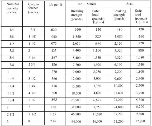
Each type of line, natural fiber, synthetic and wire rope, have different breaking strengths and safe working loads. Natural breaking strength of manila line is the standard against which other lines are compared. Synthetic lines have been assigned “comparison factors” against which they are compared to manila line. The basic breaking strength factor for manila line is found by multiplying the square of the circumference of the line by 900 lbs.
As an example, if you had a piece of ½” manila line and wanted to find the breaking strength, you would first calculate the circumference. (.5 X 3.14 = 1.57) Then using the formula above:
To calculate the breaking strength of synthetic lines you need to add one more factor. As mentioned above, a comparison factor has been developed to compare the breaking strength of synthetics over manila. Since synthetics are stronger than manila an additional multiplication step is added to the formula above.
Using the example above, letÂ’s find the breaking strength of a piece of ½” nylon line. First, convert the diameter to the circumference as we did above and then write the formula including the extra comparison factor step.
Knots and splices will reduce the breaking strength of a line by as much as 50 to 60 percent. The weakest point in the line is the knot or slice. However, a splice is stronger than a knot.
Just being able to calculate breaking strength doesn’t give one a safety margin. The breaking strength formula was developed on the average breaking strength of a new line under laboratory conditions. Without straining the line until it parts, you don’t know if that particular piece of line was above average or below average. For more information, we have discussed the safe working load of ropes made of different materials in this article here.
It’s very important to understand the fundamental differences between the tensile strength of a rope, and a rope’s working load. Both terms refer to rope strength but they’re not the same measurement.
A rope’s tensile strength is the measure of a brand-new rope’s breaking point tested under strict laboratory-controlled conditions. These tests are done by incrementally increasing the load that a rope is expected to carry, until the rope breaks. Rather than adding weight to a line, the test is performed by wrapping the rope around two capstans that slowly turn the rope, adding increasing tension until the rope fails. This test will be repeated on numerous ropes, and an average will be taken. Note that all of these tests will use the ASTM test method D-6268.
The average number will be quoted as the rope’s tensile strength. However, a manufacturer may also test a rope’s minimum tensile strength. This number is often used instead. A rope’s minimum tensile strength is calculated in the same way, but it takes the average strength rating and reduces it by 20%.
A rope’s working load is a different measurement altogether. It’s determined by taking the tensile strength rating and dividing it accordingly, making a figure that’s more in-line with an appropriate maximum load, taking factors such as construction, weave, and rope longevity into the mix as well. A large number of variables will determine the maximum working load of a rope, including the age and condition of the rope too. It’s a complicated equation (as demonstrated above) and if math isn’t your strong point, it’s best left to professionals.
However, if you want to make an educated guess at the recommended working load of a rope, it usually falls between 15% and 25% of the line’s tensile strength rating. It’s a lotlower than you’d think. There are some exceptions, and different construction methods yield different results. For example, a Nylon rope braided with certain fibers may have a stronger working load than a rope twisted out of natural fibers.
For safety purposes, always refer to the information issued by your rope’s manufacturer, and pay close attention to the working load and don’t exceed it. Safety first! Always.
If you’re a regular sailor, climber, or arborist, or just have a keen interest in knot-tying, be warned! Every knot that you tie will reduce your rope’s overall tensile strength. Some knots aren’t particularly damaging, while others can be devastating. A good rule of thumb is to accept the fact that a tied knot will reduce your rope’s tensile strength by around 50%. That’s an extreme figure, sure, but when it comes to hauling critical loads, why take chances?
Knots are unavoidable: they’re useful, practical, and strong. Splices are the same. They both degrade a rope’s strength. They do this because a slight distortion of a rope will cause certain parts of the rope (namely the outer strands) to carry more weight than others (the inner strand). In some cases, the outer strands end up carrying all the weight while the inner strands carry none of it! This isn’t ideal, as you can imagine.
Some knots cause certain fibers to become compressed, and others stretched. When combined together, all of these issues can have a substantial effect on a rope’s ability to carry loads.
Naturally, it’s not always as drastic as strength loss of 50% or more. Some knots aren’t that damaging, some loads aren’t significant enough to cause stress, and some rope materials, such as polypropylene, Dyneema, and other modern fibers, are more resilient than others. Just keep in mind that any knots or splices will reduce your rope’s operations life span. And that’s before we talk about other factors such as the weather or your rope care regime…

Wire ropes are essential for safety purposes on construction sites and industrial workplaces. They are used to secure and transport extremely heavy pieces of equipment – so they must be strong enough to withstand substantial loads. This is why the wire rope safety factor is crucial.
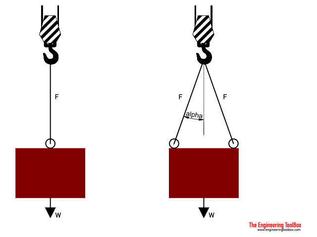
You may have heard that it is always recommended to use wire ropes or slings with a higher breaking strength than the actual load. For instance, say that you need to move 50,000 lbs. with an overhead crane. You should generally use equipment with a working load limit that is rated for weight at least five times higher – or 250,000 lbs. in this case.
This recommendation is all thanks to the wire rope safety factor. This calculation is designed to help you determine important numbers, such as the minimum breaking strength and the working load limit of a wire rope.
The safety factor is a measurement of how strong of a force a wire rope can withstand before it breaks. It is commonly stated as a ratio, such as 5:1. This means that the wire rope can hold five times their Safe Work Load (SWL) before it will break.
So, if a 5:1 wire rope’s SWL is 10,000 lbs., the safety factor is 50,000 lbs. However, you would never want to place a load near 50,000 lbs. for wire rope safety reasons.
The safety factor rating of a wire rope is the calculation of the Minimum Break Strength (MBS) or the Minimum Breaking Load (MBL) compared to the highest absolute maximum load limit. It is crucial to use a wire rope with a high ratio to account for factors that could influence the weight of the load.
The Safe Working Load (SWL) is a measurement that is required by law to be clearly marked on all lifting devices – including hoists, lifting machines, and tackles. However, this is not visibly listed on wire ropes, so it is important to understand what this term means and how to calculate it.
The safe working load will change depending on the diameter of the wire rope and its weight per foot. Of course, the smaller the wire rope is, the lower its SWL will be. The SWL also changes depending on the safety factor ratio.
The margin of safety for wire ropes accounts for any unexpected extra loads to ensure the utmost safety for everyone involved. Every year there aredue to overhead crane accidents. Many of these deaths occur when a heavy load is dropped because the weight load limit was not properly calculated and the wire rope broke or slipped.
The margin of safety is a hazard control calculation that essentially accounts for worst-case scenarios. For instance, what if a strong gust of wind were to blow while a crane was lifting a load? Or what if the brakes slipped and the load dropped several feet unexpectedly? This is certainly a wire rope safety factor that must be considered.
Themargin of safety(also referred to as the factor of safety) measures the ultimate load or stress divided by theallowablestress. This helps to account for the applied tensile forces and stress thatcouldbe applied to the rope, causing it to inch closer to the breaking strength limit.
A proof test must be conducted on a wire rope or any other piece of rigging equipment before it is used for the first time.that a sample of a wire rope must be tested to ensure that it can safely hold one-fifth of the breaking load limit. The proof test ensures that the wire rope is not defective and can withstand the minimum weight load limit.
First, the wire rope and other lifting accessories (such as hooks or slings) are set up as needed for the particular task. Then weight or force is slowly added until it reaches the maximum allowable working load limit.
Some wire rope distributors will conduct proof loading tests before you purchase them. Be sure to investigate the criteria of these tests before purchasing, as some testing factors may need to be changed depending on your requirements.
When purchasing wire ropes for overhead lifting or other heavy-duty applications, understanding the safety dynamics and limits is critical. These terms can get confusing, but all of thesefactors serve an important purpose.
Our company has served as a wire rope distributor and industrial hardware supplier for many years. We know all there is to know about safety factors. We will help you find the exact wire ropes that will meet your requirements, no matter what project you have in mind.
It’s rare for a week to go by here at Industrial Wire Rope without discussions about tensile strength or working load limit. We take it for granted that most people in our industry know there is a difference in the meaning of these terms. Yet, these terms and others are highly interrelated, and we thought an overview of them on one page might be a helpful reference. For those who want to dive deeper into the definitions and how they apply on the job, we’re also providing links to sources with additional information.
Let’s start with Tensile Strength. As we described in a post from 2017, “Tensile strength is a measurement of the force required to pull something such as rope, wire, or a structural beam to the point where it breaks. The tensile strength of a material is the maximum amount of tensile stress that it can take before failure, for example breaking.”
In our immediate world, tensile strength is the force required to break the ropes we offer. Tensile strength is determined by testing. Obviously, it is different for every type of rope, being a function of the material and construction of each type.
Although tensile strength is a definitive quantity measuring the force required to break a rope, working load limit is a measure that takes a wide range of variables into account. And always, the tensile strength of a material is greater than the recommended working load limit.
The working load limit provides consideration for factors such as the abrasion, friction and rubbing the rope is subjected to, the variance in temperature extremes it is exposed to, harmful substances that may come into contact with it, age, and even knots in the rope. Working load limit is defined as “the maximum load which should ever be applied to the product, even when the product is new and when the load is uniformly applied”.
Working load limit is always a fraction of tensile strength, allowing for a generous margin of safety. For wire ropes, it’s common for the working load limit to be set at 20% of tensile strength. However, you generally don’t have to be concerned about doing the math on your own. Rope manufacturers typically mark the working load limit on the products, so the information should be readily available to you.
Have you picked up a ratchet strap and saw numbers labeled on the strap, and wonder what they mean? Chances are you"re reading the working load limit or break strength. Every piece of load-bearing equipment states these requirements to let you know how much weight that piece of rigging is capable of securing.
When it comes to securing fragile or heavy loads, it is crucial that the product can secure the load without breaking. Although these terms are normally stated, there is confusion about what these terms mean. Read on below to learn what working load limit, break strength, and safety factor mean.
Many people ask about the working load limit, and this is a term to not mix up with breaking strength. Abbreviated as WLL, it is the rating that should never be exceeded when using a product like a ratchet strap. Before using a piece of load-bearing equipment, always make sure to look at the working load limit before use as it is the maximum allowable loading force.
Something to keep in mind is the working load limit is always 1/3 of the breaking strength. So if a ratchet strap has a breaking strength of 15,000 pounds, then the strap will have a working load limit of 5,000 pounds.
The break strength is equally as important as the WLL. The break strength also refers to the point at which your load-bearing equipment will fail. It is expressed in pounds and/or kilograms, and will actually fail if you go over the required amount.
When a ratchet strap is made with webbing, end fittings, and a ratchet all with a 10,000-pound breaking strength, then the break strength of the overall product will stay 10,000 pounds. However, if the same strap has a ratchet with an 8,000-pound break strength, then that would reduce the product"s strength to 8,000.
Safety factor, also known as Design Factor, determines the ratio between the working load limit and break strength. The working load limit"s rating should never exceed when using a sling or tiedown, and this safety factor provides an allowance for shock loading, G force, and other unforeseen factors.
When selecting a ratchet strap, lifting sling, shackle, or any other product, select the product that has suitable characteristics for the type of load, environment, and attachment to the vehicle.
At US Cargo Control, we want you to be safe when securing heavy loads. If you have any questions about the safety requirements, give our team a call at 800-404-7068 or email us at customerservice@uscargocontrol.com.
The use of rope for any purpose results in friction, bending and tension. All rope, hardware, sheaves rollers, capstans, cleats, as well as knots are, in varying degrees, damaging to ropes. It’s important to understand that rope is a moving, working, strength member and even under the most ideal conditions will lose strength due to use in any application. Maximizing the safety of rope performance is directly related to how strength loss is managed and making sure ropes are retired from service before a dangerous situation is created. Ropes are serious working tools and used properly will give consistent and reliable service. The cost of rope replacement is extremely small when compared to the physical damage or personnel injury that can result from using a worn out rope.
There are basically three steps to consider in providing the longest possible service life for ropes, the safest conditions and long range economy: Selection, Usage and Inspection.
Selecting a rope involves evaluating a combination of factors. Some of these factors are straight forward, like comparing rope specifications. Others are less qualitative, like color preference or how a rope feels while handling. Cutting corners, reducing design factors, sizes or strengths on an initial purchase creates unnecessary replacements, potentially dangerous conditions and increased long term costs. Fiber and construction being equal, a larger rope will outlast a smaller rope, because of greater surface wear distribution. By the same token, a stronger rope will outlast a weaker one, because it will be used at a lower percentage of its break strength and corresponding Work Load Limit with less chance of overstressing. The following factors should be considered in your rope selection: Strength, Elongation, Firmness, Construction and Abrasion.
When given a choice between ropes, select the strongest of any given size. A load of 200 pounds represents 2% of the strength of a rope with a 10,000 Lbs. breaking strength. The same load represents 4% of the strength of a rope that has a 5,000 Lbs. breaking strength. The weaker rope will work harder and as a result will have to be retired sooner. Braided ropes are stronger than twisted ropes that are the same size and fiber type.
Please note that the listed break strengths are average break strengths and do not consider conditions such as sustained loads or shock loading. Listed break strengths are attained under laboratory conditions. Remember also that break strength is not the same as the Work Load Limit.
It is well accepted that ropes with lower elongation under load will give you better control. However, ropes with lower elongation that are shock loaded, like a lowering line, can fail without warning even though the rope appears to be in good shape. Low elongating ropes should be selected with the highest possible strength. Both twisted ropes and braided ropes are suitable for rigging. Size for size, braided rope has higher strength and lower stretch than a twisted rope of similar fiber. See page 390 for additional information on rope elongation.
Select ropes that are firm and hold their shape during use. Soft or mushy ropes will snag easily and abrade quickly causing accelerated strength loss.
Rope construction plays an important role in resistance to normal wear and abrasion. Braided ropes have a basically round, smooth construction that tends to flatten out somewhat over the bearing surface. Flattening distributes wear over a much greater area, as opposed to the crowns of a three strand or to a lesser degree, an eight strand rope.
All rope will be severely damaged if subjected to rough surfaces or damaging edges. All rope must be protected against damaging or abrasive surfaces. Wire rope will score and gouge chocks and bitts creating cutting edges that can damage synthetic ropes. Chocks, bitts, drums and other surfaces must be kept in good condition and free of burrs and rust. Weld beads on repaired capstans, fairleads, etc., are equally damaging, unless dressed down smoothly. Pulleys must be free to rotate and should be of proper size to avoid
Avoid using a rope that shows signs of aging and wear. If in doubt, do not use the rope. Damaged rope must be destroyed to prevent any future use. No visual inspection can be guaranteed to accurately and precisely determine the residual strength of the rope. When fibers show wear in any area, the damaged area must be removed and the rope should be re-spliced or replaced. Check regularly for frayed or broken strands. Pulled strands should be rethreaded into the rope if possible. A pulled strand can snag on a foreign object during usage. Both outer and inner rope fibers may contribute to the strength of the rope. When either is worn the rope is naturally weakened. Open the strand of the rope and inspect for powdered fiber, which is one sign of internal wear. A heavily used rope will often become compacted or hard, which indicates reduced strength. The rope should be discarded and made unusable if this condition is detected. See pages 395 and 396 for additional inspection information.
New rope tensile strength is based upon tests of new and unused spliced rope of standard construction in accordance with Samson testing methods, which conform to Cordage Institute, ASTM and OCIMF test procedures. It can be expected that strengths will decrease as soon as a rope is put into use. Because of the wide range of rope use, changes in rope conditions, exposure to the many factors affecting rope behavior and the possibility of risk to life and property, it is impossible to cover all aspects of proper rope applications or to make generalized statements as to Work Load Limits.
Work Load Limits are the load that a rope in good condition with appropriate splices in non-critical applications is subjected to during normal activity. They are normally expressed as a percentage of new rope strength and should not exceed 20% of the stated break strength. Thus, your maximum Work Load Limit would be 1/5 or 20% of the stated break strength.
A point to remember is that a rope may be severely overloaded or shock loaded in use without breaking. Damage and strength loss may have occurred without any visible indication. The next time the rope is used under normal Work Loads and conditions, the acquired weakness can cause it to break.
Normal Work Load Limits do not cover dynamic conditions such as shock loads or sustained loads, nor do they apply where life, limb or property are involved. In these cases a stronger rope must be used and/or a higher design factor applied.
Normal Work Load Limits are not applicable when rope is subjected to dynamic loading. Whenever a load is picked up, stopped, moved or swung there is increased force due to dynamic loading. The more rapidly or suddenly such actions occur, the greater the increase in the dynamic loading. In extreme cases, the force put on the rope may be two, three or many more times the normal Work Load involved. Examples of dynamic loading would be: towing applications, picking up a load on a slack line or using a rope to stop a falling object. Dynamic loading affects low elongation ropes like polyester to a greater degree than higher elongation, nylon ropes. Dynamic loading is also magnified on shorter length ropes when compared to longer rope lengths. Therefore, in all such applications, normal Work Load Limits do not apply.
IMPORTANT NOTE: Many industries are subject to state and federal regulations for Work Load Limits that supersede those of the manufacturer. It is the responsibility of the user to be aware of and adhere to those laws and regulations.
Work Load Limits as described do not apply when ropes have been subjected to shock loading. Whenever a load is picked up, stopped, moved or swung, there is an increased force due to dynamic loading. The more rapidly or suddenly such actions occur, the greater this increase in force will be. The load must be handled slowly and smoothly to minimize dynamic effects. In extreme cases, the force put on the rope may be two, three or even more times the normal Work Load involved. Examples of shock loading are picking up a tow on a slack line or using a rope to stop a falling object. Therefore, in all applications such as towing lines, life lines, safety lines, climbing ropes, etc., design factors must reflect the added risks involved. Users should be aware that dynamic effects are greater on a low elongation rope such as manila than on a high-elongation rope such as nylon and greater on a shorter rope than on a longer one.
The shock load that occurs on a winch line when a 5,000 Lbs. object is lifted vertically with a sudden jerk may translate the 5,000 Lbs. of weight into 30,000 Lbs. of dynamic force, which could cause the line to break. Where shock loads, sustained loads or where life, limb or valuable property is involved, it is recommended that a much higher design factor than 5 be used.
Remember, shock loads are simply a sudden change in tension, from a state of relaxation or low load to one of high load. The further an object falls, the greater the impact. Synthetic fibers have a memory and retain the effects of being overloaded or shock loaded. Ropes that have been shock loaded can fail at a later time, when used within Work Load Limits.

As a wire rope is used, the outer wires wear through abrasion and so the rope suffers loss of cross-sectional area – this obviously reduces the breaking strength of the wire rope. Resistance to abrasive wear is therefore an important property of a wire rope.
Abrasion resistance is directly related to the design of the rope, in particular the design of the strands of the rope. In general, ropes with fewer larger wires will be more abrasion resistant than a similar rope made up of smaller wires – a 6 x 19 rope will therefore be more abrasion resistant than a 6 x 36 rope.
In a later article in this technical series we will discuss fatigue resistance in great detail but for the purposes of this discussion, we must recognise that a cyclic stress reversal occurs when a body is subjected to alternating tensile and compressive loads.
In a drilling operation, wire ropes run through sheaves constantly and so are constantly subjected to alternating tensile and compressive loads – i.e. cyclic stress reversals.
Figure 1 illustrates a wire rope bending over a sheave. It is clear that the outer parts of the rope running over the sheave are in tension and the inner parts of the rope running over the sheave are in compression and as the rope moves over the sheave these stresses reverse.
It should be obvious that the smaller the diameter of the sheave the greater the magnitude (amplitude) of the stress reversal and so the more rapidly fatigue will occur in the rope.
Wire ropes experience external forces that will tend to alter or distort the shape of the rope. Crushing prevents wires and strands moving easily over one another during normal operation and this can lead to accelerated wear and reduced rope life.
Wire rope is the lifeline of your tow truck. We’ll help you understand the terminology, construction and ratings of wire rope. We’ll also give you advice on what type of rope to buy, how to attach it to a hook without losing towing capacity, how to inspect and maintain it, how to prevent damage, and how to tell when it’s time to replace it. We’ll also give the pros and cons of synthetic versus wire rope.
“Wire rope,” “line,” “rope” or “wire” are the only correct ways to refer to wire rope, but many tow operators refer to it as cable. Wire rope is not cable. Cable is only an acceptable term when referring to a piece of wire rope that is terminated on both ends. When that cable is connected to a power source, such as a winch, it’s no longer acceptable to call it cable.
The Egyptians were among the first to twist and braid strands of plant material together to form rope. Today’s rope is made of different materials and using different methods, but the basic principle remains the same: smaller diameter material is twisted to form strands, and then those strands are twisted to form the rope (or wire, if the rope is made from steel).
The pictures below show a 6 x 19 wire rope. The ‘19’ refers to the number of smaller diameter wires that are twisted together to form a single strand. The ‘6’ refers to the number of strands that are twisted together to make the wire. The middle of the rope, which isn’t included in either number, is referred to as “the core.”
You might have seen the term “lay” when a manufacturer specifies the type of wire to be used on a piece of their equipment. Lay refers to the direction of the twist of the wires in a strand (right or left) and to the direction that the strands are laid in the rope (regular or lang).
When you inspect a rope with regular lay, the wires appear to run straight down the length of the rope. With lang lay, the wires twist in the same direction as the strands, giving the appearance that the wires run across the rope. Regular lay rope is the most common wire sold today.
Just because your wire rope says it’s rated for an ultimate load (UL, or breaking strength) of 39,000 lbs doesn’t mean you can use that rope to tow 39,000 lbs. That’s because every wire rope has a working load limit (or WLL), which is the actual mass or force the product can support. It’s the working load limit you shouldn’t exceed, not the ultimate load limit.
So why don’t rope manufacturers make our lives easier by giving the WLL on their packaging instead of the UL? That’s because wire rope can handle different weights depending on how it’s being used. Different industries have different WLLs.
For example, standard 1/2” 6 x 19 wire rope has an ultimate load of 26,600 lbs. The working load limit for towing and recovery is 26,600 divided by 4, which is 6,650 lbs.
Synthetic rope is becoming a popular tool in the towing and recovery industry for many reasons. It has a significantly higher rating compared to standard wire, it is much lighter and, because it has no memory, there is less risk of damage caused by bird nesting.
Over the last few years, synthetic rope has also become more available to our industry. There are a wide range of distributors stocking the common sizes.
As with any synthetic product, synthetic rope is more susceptible to damage from sharp edges, but synthetic ropes made with Dyneema fiber is incredibly durable.
The three most common terminations used when attaching a hook to a wire rope are a Flemish eye with thimble splice, open swage socket, and wedge and socket (Becket). The most common of all the terminations is the Flemish eye with thimble splice.
In all cases except the open swage socket (pictured below), the rated capacity of wire rope is reduced when a termination is added to the end of the wire. When a Flemish eye with thimble splice is installed properly, it preserves 90 to 96% of the rope’s rated capacity.
The wedge and socket (pictured below) is the least recommended termination and should only be used to repair a wire that has been damaged in the field. The termination efficiency for the wedge and socket is 80% of the wire’s rated capacity. That means if we install a wedge and socket on the standard 1/2” 6 x 19, our working load limit is reduced to 5,320 lbs (WLL of 6,650 lbs x 0.8 = 5,320 lbs).
We don’t recommend using wire rope clips to terminate a hook on wire rope. Many times these clips are not installed correctly, which significantly reduces the termination efficiency.
Grade of steel. Wire rope is constructed with different grades of steel the same way that chain is manufactured. The most common wire rope grade is extra improved plow steel (EIPS) but you can also select extra extra improved plow steel (EEIPS) that is 10% stronger.
Steel core vs fiber core. When wire rope is constructed, the strands and wires are wrapped around a center core made of either independent wire rope core (IWRC) or fiber core (FC). IWRC, which is made of steel, provides additional strength. Fiber core cushions the strands by accepting lubricant more effectively. For the towing industry, we feel that the benefit of increasing our single line rating with steel core wire outweighs the benefits that fiber core offers.
Strength of rope. When it comes to wire rope, as with many things in life, you get what you pay for. A 1/2” standard 6 x 19 steel core wire rope has a working load limit of 6,650 lbs. If you go for a ½” Python COMPAC 6 steel core rope, your WLL increases to 7,550 (14% increase). Opt for a ½” Python COMPAC 35 steel core rope and your WLL increases to 9,100 (a 37% increase over then standard wire). The COMPAC 35 rope will cost you three times the price of the standard 6-strand wire, though.
Lang lay or regular lay. There are advantages and disadvantages to both lang and regular lay wire rope, depending on the application. Most manufacturers specify the types and lays of wire rope to be used on their piece of equipment. Be sure to consult the operator’s manual for proper application.
Quality of manufacturer. Talk to your wire rope supplier about the rope manufacturer. Imported wire rope is very common in today’s marketplace and many of these suppliers are quality manufacturers. The only way you can tell the quality is by asking questions about the product you’re buying.
It’s important to regularly inspect your wire rope for damage. The most common signs of damage are broken strands, kinks, and flat spots from improper wrapping on the winch drum. Constantly inspect your wire during a recovery to ensure that the winch is gathering wire properly on the winch drum and the wire is properly layered on the winch. If you want to prolong the life of your rope, take the time to unwind and rewind your wire at the first sign of overlapping or bird nesting and always stay within the working load limit.
Depending on the amount of wear and tear your wire is exposed to, you may need to replace it more often. In order to determine when you need to replace your wire, you must unwind it from the winch drum and inspect each foot of wire to determine if it needs attention. This is also a perfect time to lubricate your wire when you wind it back onto the winch. We recommend replacing your wire rope at the first sign of overloading.
It’s important to remember that most wire ropes fail from the inside out. Wire rope lubricant prolongs the life of your wire by protecting it from rust and corrosion while at the same time keeping it flexible. The best lubricant is one that was specifically designed for wire rope. Select a lubricant that doesn’t contain acids or alkalis. We recommend a moly or asphalt-based lubricant. Don’t apply used oils.
In order to protect ourselves and others from injury we must have the confidence in the equipment we are using. You can now speak to your rope supplier with confidence. Ask questions about the product you are about to buy. You never know if it is a quality manufactured piece of equipment.
The Working Load Limit is the maximum load which should ever be applied to the product, even when the product is new and when the load is uniformly applied – straight line pull only. Avoid side loading. All catalog ratings are based upon usual environmental conditions and consideration must be given to unusual conditions such as extreme high or low temperatures, chemical solutions or vapors, prolonged immersion in salt water, etc. Never exceed the Working Load Limit.
The term “Proof Test” designates a quality control test applied to the product for the sole purpose of detecting defects in material or manufacture. The Proof Test Load (usually twice the Working Load Limit) is the load which the product withstood without deformation when new and under laboratory test conditions. A constantly increasing force is applied in direct line to the product at a uniform rate of speed on a standard pull testing machine. The Proof Test Load does not mean the Working Load Limit should ever be exceeded.
Do not use breaking strength as a criterion for service or design purposes. Refer to the Working Load Limit instead. Breaking Strength is the average force at which the product, in the condition it would leave the factory, has been found by representative testing to break, when a constantly increasing force is applied in direct line to the product at a uniform rate of speed on a standard pull testing machine. Proof testing to twice the Working Load Limit does not apply to hand-spliced slings. Remember: Breaking Strengths, when published, were obtained under controlled laboratory conditions. Listing of the Breaking Strength does not mean the Working Load Limit should ever be exceeded.
An industry term usually computed by dividing the catalog Breaking Strength by the catalog Working Load Limit and generally expressed as a ratio. For example: 5 to 1.
A load resulting from rapid change of movement, such as impacting, jerking or swinging of a static load. Sudden release of tension is another form of shock loading. Shock loads are generally significantly greater than static loads. Any shock loading must be considered when selecting the item for use in a system.

Wire rope is also known by many other names, such as: wire, multi-strand wire, flexible wire, cable, cord, steelcord, etc. but it is essentially a collection of small filaments wound around each other in a manner that largely retains its shape when bent, crushed and/or tensioned.
It is a system for significantly increasing the strength and flexibility of steel wire and is used in almost every important application we see around us. For example: suspension bridges, tyres, brake and accelerator cables (in cars), high-pressure flexible pipes, lifting and rigging cables, electrical conductors, etc. and it comes in many different forms. Fig 2 shows just a very small sample of available designs.
With minor variations, the generally accepted method for designating a wire rope construction in the industry is by describing it numerically. For example:
Whilst "IWRC" wire ropes offer a slightly greater tensile capacity (≈7%) than those with fabric or polymer fillers, the additional strength does not come from the tensile capacity of the core filaments but from improved dimensional stability under load. And whilst they are also much more resistant to crushing, they are stiffer than fibre core ropes and therefore not recommended for applications where tension occurs under bending.
Warrington (Fig 1) is a parallel lay construction with an outer layer comprising wires of alternating large and small diameters, each outer layer having twice the number of wires as the layer immediately beneath. The benefit of this design is to increase packing and therefore strength density, however, unless the different diameter filaments are of the same strength (unlikely), this construction is limited by the strength of the weakest filaments.
Seale (Figs 1 & 2 6x36) is also a parallel lay construction but with the same number of wires in each wire layer. All the wires in any layer are the same diameter. This is an alternative to the Warrington construction, with similar benefits and disadvantages.
Regular lay constructions are used much more widely (than Lang lay) because they have excellent structural stability and less tendency to unwrap under tension (see Rotating vs Non-Rotating below). However, because it has a knobbly (undulating) surface it will wear both itself and any surface over which it is run much more quickly than Lang lay wire rope.
Lang lay constructions have a flatter surface than regular lay constructions giving them better resistance to wear and bending fatigue, especially when made from flattened (elliptical) filaments. They are, however, much less structurally stable and subject to birdcaging if the wire rope is over-bent or twisted against its wrapped direction.
"Regular Lay", multi-strand constructions are normally subject to slightly less rotation under tension (than Lang lay) due to the opposite helical direction of the filaments (within the strands) and the strands (within the rope), however, you can improve their rotation characteristics still further by;
Fillers (Fig 2) may be fabric, polymer or even smaller diameter filaments (e.g. 6x36). Whilst they contribute little to the tensile strength of wire rope, they can significantly; improve performance under bending (fabric and polymer cores only), reduce axial growth, reduce rotation in rotation-resistant constructions, improve structural stability and increase fatigue life.
This filler material should not be included in strength (tensile capacity) calculations, but must be included in those for axial stiffness (extension). If it is ignored, your calculations will reveal excessive extension as the wire rope collapses.
Suspension bridges tend to be constructed from densely packed, single strand plain "Wire Rope" constructions using large diameter galvanised filaments. Little heed is paid to rotational resistance as strength is paramount and once tensioned, they should remain in that loading condition for their design life.
Lifting & winching normally require wire ropes of good flexibility and fatigue resistance. Therefore they tend to be similar to 6x36 but with fibre core instead of the IWRC in Fig 2
Hosecord is suitable for HPHT flexible pipes as lateral flexibility is generally considered less important than minimal longitudinal growth or maximum tensile strength (per unit cross-sectional area).
Remote operating cables such as hand-brakes and accelerators on cars normally only work in tension so they need to be strong but not necessarily stiff (as they are fully contained in reinforced outer sheaths). These tend to be manufactured from large diameter "TyreCord" or small diameter single-strand "Wire Rope".
Wire rope does not obey Hooke"s law. Therefore, you cannot accurately predict how much it will stretch for any specified force. This unpredictability applies to any section removed from the same manufactured length of cord and even between cords produced to the same specification but by different manufacturers.
CalQlata has decided that the accuracy of axial stiffness (EA) of wire rope falls outside its own levels of acceptability and therefore does not include it in the wire rope calculator. The extension calculated in the Wire Rope calculator (δLᵀ) is based upon the effect of axial tension on packing density. It is therefore important that core material is not ignored when using the calculator to evaluate this characteristic.
Wire rope does not obey Hooke"s law. Therefore, you cannot accurately predict how much it will twist for any specified torque. This unpredictability applies to any section removed from the same manufactured length of cord and even between cords produced to the same specification but by different manufacturers.
CalQlata has decided that the accuracy of torsional stiffness (GJ) of wire rope falls outside its own levels of acceptability and therefore does not include it in the wire rope calculator.
1) No wire rope calculator, whether dedicated or generic, will accurately predict the properties of any single construction under a wide range of loading conditions
2) No wire rope calculator, whether dedicated or generic, will accurately predict any single property for a range of constructions under a wide range of loading conditions
The only wire rope that can be reliably analysed is that which is used for suspension bridges, because; it comprises a single strand, is very densely packed, has negligible twist, contains filaments of only one diameter, is never subjected to minimum bending and every filament is individually tensioned.
There is a very good reason why manufacturers do not present calculated performance data for construction or design proposals, because even they cannot accurately predict such properties and quite rightly rely on, and publish, test data.
During his time working in the industry, the wire rope calculator"s creator has seen, created and abandoned numerous mathematical models both simple and complex. He has gradually developed his own simplified calculation principle based upon his own experience that still provides him with consistently reliable results of reasonable accuracy.
The purpose of CalQlata"s wire rope calculator is to provide its user with the ability to obtain a reasonable approximation for a generic construction, after which, accurate test data should be sought from the manufacturer for the user"s preferred construction.
The calculation principle in the wire rope calculator is based upon changes in the properties of the wire rope that occur with variations in packing density under tension
Bearing in mind the above limitations CalQlata can provide the following assistance when generating (manipulating) the wire rope calculator"s input data and interpreting its output
Alternatively, for wire rope with multiple filament diameters, you need to find an equivalent diameter with the following proviso; you must enter the minimum filament yield stress (SMYS)
It is expected that apart from fillers, all the material in the wire rope will be identical and therefore have the same density, i.e. using different materials will result in less than "best" performance. However, if such a construction is proposed, you can calculate an equivalent density as follows:
It is expected that apart from fillers, all the material in the wire rope will be identical and therefore have the same tensile modulus, i.e. using different materials will result in less than "best" performance. However, if such a construction is proposed, you should enter the highest tensile modulus.
The wire rope calculator simply adds together the total area of all the filaments and multiplies them by the SMYS entered, which represents a theoretical maximum breaking load that would exist if this load is equally shared across all of the filaments and the lay angles have been arranged to eliminate localised (point) loads between adjacent filaments.
If the wire rope has been properly constructed it is likely that its actual break load will be greater than 80% of this theoretical value. However, given the vagaries of wire rope construction, the actual break load can vary considerably dependent upon a number of factors. CalQlata suggest that the following factors may be used to define the anticipated break load of any given construction:
The axial stiffness and strain under load will be affected by this value, hence the reason why the most reliable (predictable) constructions tend to be minimum [number of] strands and single filament diameter. The Warrington and Seale constructions and combinations thereof tend to provide the highest packing density (but lowest flexibility) and there is little to be gained from using these constructions in more than single stranded wire rope as the benefit of high-packing density will be lost with no gain in flexibility.
The anticipated second moment of area of the wire rope at tension "T" due to deformation but insignificant flattening as it is assumed the wire rope will be bent over a formed (shaped) sheave or roller.
The anticipated tensile modulus of the wire rope at tension "T" due to deformation but insignificant flattening as it is assumed the wire rope will be bent over a formed (shaped) sheave or roller.
It is not advisable to induce this bend radius in operation due to uncertainties associated with wire rope construction, especially for dynamic applications. CalQlata suggests that a similar approach to that used for the break load (Fb) above also be applied here, i.e.:
A change in diameter will occur in all wire rope, irrespective of construction, until packing density has reached a limiting value. The value provided in the wire rope calculator is that which would be expected if the construction remains intact at the applied tension "T"
Unreliability of this value increases with complexity in wire rope due to its longitudinal variability and the increased likelihood of premature failure.
The accuracy of this data will range from about ±1% for wire rope with a single strand and a single filament diameter, up to about ±15% for constructions of similar complexity to OTR cord
A change in length of any wire rope will occur due to the fact that the packing density increases with tension. This is not, however, a linear relationship.
This can be an unreliable value as illustrated by tests carried out (by the author) on two pieces of wire rope supplied by the same well-known manufacturer both of which were cut from the same length, varied in tensile capacity by only 1.5%, but the tensile modulus (and strain at break) varied by 34%. Whilst this was an extreme case, significant variations have been seen in wire rope manufactured by a number of manufacturers.
Whilst the wire rope calculator does not calculate axial stiffness (see Calculation Limitations 9) above), CalQlata can suggest the following rule-of-thumb that will provide reasonable results for most constructions at the applied tension "T":
Where: θ = the "absolute" sum of the average filament lay angle and the average strand lay angle⁽²⁾. Note; the angle of twist (θ) will reduce as tension approaches break load.
Whilst the wire rope calculator does not calculate bending stiffness (see Calculation Limitations 8) above), CalQlata can suggest the following rule-of-thumb that will provide reasonable results for most constructions at the applied tension "T":
Low complexity means single strand and single wire diameter. Medium complexity means multi-strand and single wire diameter. High complexity means multi-strand and multiple wire diameters.
In selecting the right steel wire rope, it is important to determine how important the various properties are in relation to the application and then to assign priorities to these. It is also important to be aware of the relevant standards and regulations. If you are in any doubt, please contact our sales consultants or our Technical Department.
The tensile strength of the steel wire rope depends on the rope’s dimensions, the tensile strength of the wires and the construction. The minimum guaranteed tensile strength for the different kinds of rope is shown in the Randers Reb product catalogue.
The design of the steel wire rope does not significantly affect the tensile strength (up to approx. 5%). A change of core from fibre to steel makes slightly more difference (approx. 10%). The greatest change is achieved by changing the dimensions, usage of Compacted steel wire ropes or tensile strength of the wires (see also fig. 28).
It is often required that the steel wire rope must have a specific SWL value (Safe Working Load), also known as a WLL value (Working Load Limit). This means the steel wire rope’s tensile strength divided by the safety factor required for the relevant application.
Steel wire ropes with thick outer wires (e.g. 6x7 Standard or 6x19 Seale) provide good abrasion resistance. Lang lay ropes provide better abrasion resistance than regular lay steel wire ropes (see also fig. 28). Abrasion resistance can also be increased by using wires with greater tensile strength.
The greater the number of wires in the strand, the greater the bending fatique resistance and flexibility. Lang lay ropes provide better bending fatique resistance than regular lay steel wire ropes. Bending fatique resistance can also be increased by using pre-formed steel wire ropes (see also fig. 28).
Galvanised and rustproof wires provide excellent protection against corrosion. Lubrication with special types of grease or oil will also increase resistance to corrosion. If the steel wire rope is subjected to significant corrosive influences, it is recommended that strands with thick outer wires are used.
Steel wire ropes with fewer wires (e.g. 1x7 Standard and 1x19 Standard) are subject to the least elongation (have the greatest elasticity modulus). This type of steel wire rope is ideally suited for guy ropes, but is not suitable to be run over sheaves/blocks. If only a small degree of elongation when running over sheaves is required, 6x7 or 6x19 steel wire rope should be used, in each case with a steel core or with certain special constructions. For larger dimensions, 6x36 steel wire rope with a steel core can also be used (see also Elongation and Pre-stretching, page 8-28).
Standard 6-lay and 8-lay steel wire ropes will rotate when they hang free and carry a load. Regular lay steel wire rope provides greater resistance to rotation than lang lay steel wire rope. A steel wire rope with a steel core rotates less than a steel wire rope with a fibre core. The type of rope that provides greatest resistance to rotation is, as the name suggests, low-rotation and rotation-resistant steel wire rope (special constructions, see also ”Low-Rotation and Rotation-Resistant Steel Wire Rope”, page 8-10).
A steel core provides better support for the strands than a fibre core, which is why the risk of flattening is less in a steel wire rope with a steel core. Strands with fewer, thicker wires have greater resistance to flattening/crushing. Also, a 6-lay steel wire rope has greater crushing resistance than an 8-lay rope (see also fig. 28).
Vibrations, from wherever they might come, send shock waves through the steel wire rope, which will be absorbed by the steel wire rope at some point, and in some cases they may cause localised destruction of the steel wire rope (not necessarily on the outside). This may, for example, be at places where the steel wire rope comes into contact with a sheaf/block, or enters the drum, and by the end terminals. In general, those steel wire ropes with the greatest flexibility also have the greatest vibration resistance.
Changes in the tension of a steel wire rope, depending on the size and frequency, will reduce the rope’s life expectancy. In general, steel wire ropes with the greatest flexibility can cope better with intermittent loading. Great care should be taken in the use of end terminals or fittings, as their pulsation resistance is equally as important as the selection of the right steel wire rope.
Lang lay steel wire ropes are the ones most suited to running over sheaves and are the most durable, but if they are to be used, three things must be observed:
The reason for Lang lay steel wire ropes’ excellent qualities of abrasion resistance and pliability is that the wires are affected/loaded in a different way and have a larger load-bearing surface than a regular lay steel wire rope (see fig. 29). Note that the largest wearing surface is on the Lang lay steel wire rope.


 8613371530291