
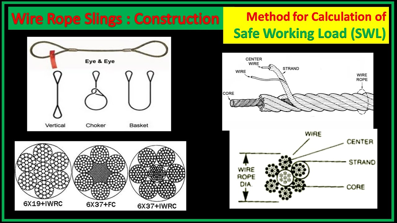
wire rope calculation formula factory
Structural Stretch is the lengthening of the lay in the construction of cable and wire rope as the individual wires adjust under load. Structural Stretch in Loos & Co., Inc. products is less than 1% of the total cable length. This form of stretch can be completely removed by applying a cable or wire rope prestretching operation prior to shipment.
Elastic Stretch is the actual physical elongation of the individual wires under load. The elastic stretch can be calculated by using the following formula*:
Wire rope is also known by many other names, such as: wire, multi-strand wire, flexible wire, cable, cord, steelcord, etc. but it is essentially a collection of small filaments wound around each other in a manner that largely retains its shape when bent, crushed and/or tensioned.
It is a system for significantly increasing the strength and flexibility of steel wire and is used in almost every important application we see around us. For example: suspension bridges, tyres, brake and accelerator cables (in cars), high-pressure flexible pipes, lifting and rigging cables, electrical conductors, etc. and it comes in many different forms. Fig 2 shows just a very small sample of available designs.
With minor variations, the generally accepted method for designating a wire rope construction in the industry is by describing it numerically. For example:
Whilst "IWRC" wire ropes offer a slightly greater tensile capacity (≈7%) than those with fabric or polymer fillers, the additional strength does not come from the tensile capacity of the core filaments but from improved dimensional stability under load. And whilst they are also much more resistant to crushing, they are stiffer than fibre core ropes and therefore not recommended for applications where tension occurs under bending.
Warrington (Fig 1) is a parallel lay construction with an outer layer comprising wires of alternating large and small diameters, each outer layer having twice the number of wires as the layer immediately beneath. The benefit of this design is to increase packing and therefore strength density, however, unless the different diameter filaments are of the same strength (unlikely), this construction is limited by the strength of the weakest filaments.
Seale (Figs 1 & 2 6x36) is also a parallel lay construction but with the same number of wires in each wire layer. All the wires in any layer are the same diameter. This is an alternative to the Warrington construction, with similar benefits and disadvantages.
Regular lay constructions are used much more widely (than Lang lay) because they have excellent structural stability and less tendency to unwrap under tension (see Rotating vs Non-Rotating below). However, because it has a knobbly (undulating) surface it will wear both itself and any surface over which it is run much more quickly than Lang lay wire rope.
Lang lay constructions have a flatter surface than regular lay constructions giving them better resistance to wear and bending fatigue, especially when made from flattened (elliptical) filaments. They are, however, much less structurally stable and subject to birdcaging if the wire rope is over-bent or twisted against its wrapped direction.
"Regular Lay", multi-strand constructions are normally subject to slightly less rotation under tension (than Lang lay) due to the opposite helical direction of the filaments (within the strands) and the strands (within the rope), however, you can improve their rotation characteristics still further by;
Fillers (Fig 2) may be fabric, polymer or even smaller diameter filaments (e.g. 6x36). Whilst they contribute little to the tensile strength of wire rope, they can significantly; improve performance under bending (fabric and polymer cores only), reduce axial growth, reduce rotation in rotation-resistant constructions, improve structural stability and increase fatigue life.
This filler material should not be included in strength (tensile capacity) calculations, but must be included in those for axial stiffness (extension). If it is ignored, your calculations will reveal excessive extension as the wire rope collapses.
Suspension bridges tend to be constructed from densely packed, single strand plain "Wire Rope" constructions using large diameter galvanised filaments. Little heed is paid to rotational resistance as strength is paramount and once tensioned, they should remain in that loading condition for their design life.
Lifting & winching normally require wire ropes of good flexibility and fatigue resistance. Therefore they tend to be similar to 6x36 but with fibre core instead of the IWRC in Fig 2
Remote operating cables such as hand-brakes and accelerators on cars normally only work in tension so they need to be strong but not necessarily stiff (as they are fully contained in reinforced outer sheaths). These tend to be manufactured from large diameter "TyreCord" or small diameter single-strand "Wire Rope".
Wire rope does not obey Hooke"s law. Therefore, you cannot accurately predict how much it will stretch for any specified force. This unpredictability applies to any section removed from the same manufactured length of cord and even between cords produced to the same specification but by different manufacturers.
CalQlata has decided that the accuracy of axial stiffness (EA) of wire rope falls outside its own levels of acceptability and therefore does not include it in the wire rope calculator. The extension calculated in the Wire Rope calculator (δLᵀ) is based upon the effect of axial tension on packing density. It is therefore important that core material is not ignored when using the calculator to evaluate this characteristic.
Wire rope does not obey Hooke"s law. Therefore, you cannot accurately predict how much it will twist for any specified torque. This unpredictability applies to any section removed from the same manufactured length of cord and even between cords produced to the same specification but by different manufacturers.
CalQlata has decided that the accuracy of torsional stiffness (GJ) of wire rope falls outside its own levels of acceptability and therefore does not include it in the wire rope calculator.
1) No wire rope calculator, whether dedicated or generic, will accurately predict the properties of any single construction under a wide range of loading conditions
2) No wire rope calculator, whether dedicated or generic, will accurately predict any single property for a range of constructions under a wide range of loading conditions
The only wire rope that can be reliably analysed is that which is used for suspension bridges, because; it comprises a single strand, is very densely packed, has negligible twist, contains filaments of only one diameter, is never subjected to minimum bending and every filament is individually tensioned.
There is a very good reason why manufacturers do not present calculated performance data for construction or design proposals, because even they cannot accurately predict such properties and quite rightly rely on, and publish, test data.
During his time working in the industry, the wire rope calculator"s creator has seen, created and abandoned numerous mathematical models both simple and complex. He has gradually developed his own simplified calculation principle based upon his own experience that still provides him with consistently reliable results of reasonable accuracy.
The purpose of CalQlata"s wire rope calculator is to provide its user with the ability to obtain a reasonable approximation for a generic construction, after which, accurate test data should be sought from the manufacturer for the user"s preferred construction.
The calculation principle in the wire rope calculator is based upon changes in the properties of the wire rope that occur with variations in packing density under tension
Bearing in mind the above limitations CalQlata can provide the following assistance when generating (manipulating) the wire rope calculator"s input data and interpreting its output
Alternatively, for wire rope with multiple filament diameters, you need to find an equivalent diameter with the following proviso; you must enter the minimum filament yield stress (SMYS)
It is expected that apart from fillers, all the material in the wire rope will be identical and therefore have the same density, i.e. using different materials will result in less than "best" performance. However, if such a construction is proposed, you can calculate an equivalent density as follows:
It is expected that apart from fillers, all the material in the wire rope will be identical and therefore have the same tensile modulus, i.e. using different materials will result in less than "best" performance. However, if such a construction is proposed, you should enter the highest tensile modulus.
The wire rope calculator simply adds together the total area of all the filaments and multiplies them by the SMYS entered, which represents a theoretical maximum breaking load that would exist if this load is equally shared across all of the filaments and the lay angles have been arranged to eliminate localised (point) loads between adjacent filaments.
If the wire rope has been properly constructed it is likely that its actual break load will be greater than 80% of this theoretical value. However, given the vagaries of wire rope construction, the actual break load can vary considerably dependent upon a number of factors. CalQlata suggest that the following factors may be used to define the anticipated break load of any given construction:
The axial stiffness and strain under load will be affected by this value, hence the reason why the most reliable (predictable) constructions tend to be minimum [number of] strands and single filament diameter. The Warrington and Seale constructions and combinations thereof tend to provide the highest packing density (but lowest flexibility) and there is little to be gained from using these constructions in more than single stranded wire rope as the benefit of high-packing density will be lost with no gain in flexibility.
The anticipated second moment of area of the wire rope at tension "T" due to deformation but insignificant flattening as it is assumed the wire rope will be bent over a formed (shaped) sheave or roller.
The anticipated tensile modulus of the wire rope at tension "T" due to deformation but insignificant flattening as it is assumed the wire rope will be bent over a formed (shaped) sheave or roller.
It is not advisable to induce this bend radius in operation due to uncertainties associated with wire rope construction, especially for dynamic applications. CalQlata suggests that a similar approach to that used for the break load (Fb) above also be applied here, i.e.:
A change in diameter will occur in all wire rope, irrespective of construction, until packing density has reached a limiting value. The value provided in the wire rope calculator is that which would be expected if the construction remains intact at the applied tension "T"
Unreliability of this value increases with complexity in wire rope due to its longitudinal variability and the increased likelihood of premature failure.
The accuracy of this data will range from about ±1% for wire rope with a single strand and a single filament diameter, up to about ±15% for constructions of similar complexity to OTR cord
A change in length of any wire rope will occur due to the fact that the packing density increases with tension. This is not, however, a linear relationship.
This can be an unreliable value as illustrated by tests carried out (by the author) on two pieces of wire rope supplied by the same well-known manufacturer both of which were cut from the same length, varied in tensile capacity by only 1.5%, but the tensile modulus (and strain at break) varied by 34%. Whilst this was an extreme case, significant variations have been seen in wire rope manufactured by a number of manufacturers.
Whilst the wire rope calculator does not calculate axial stiffness (see Calculation Limitations 9) above), CalQlata can suggest the following rule-of-thumb that will provide reasonable results for most constructions at the applied tension "T":
Whilst the wire rope calculator does not calculate bending stiffness (see Calculation Limitations 8) above), CalQlata can suggest the following rule-of-thumb that will provide reasonable results for most constructions at the applied tension "T":
Low complexity means single strand and single wire diameter. Medium complexity means multi-strand and single wire diameter. High complexity means multi-strand and multiple wire diameters.
It is also very important to know the weight calculation formula for stainless steel wire ropes. Whether you are in the industry or animal fences, it is inevitable to quote the formula for the weight of stainless steel wire rope. Calculate the exact weight and know how to arrange it.
Calculation formula: stainless steel wire rope (KG) 0.004 × diameter (mm) × diameter (mm) × length (m) = kg / m (for 7 * 7 7 * 19 7 * 37) Example: 3mm7 * 7 wire rope per meter weight = 0.004×3×3x1=0.036kg
1Stainless steel wire mesh. It is used for screening and filtration under acid and alkali environmental conditions. It is used in the oil industry as a mud network, chemical chemical fiber industry as a sieve, and electroplating industry as a pickling net. The factory can design and manufacture various types of products according to user needs. ...
3: Stainless steel wire mesh is used for screening and filtration under acid and alkali environmental conditions. The petroleum industry is used as mud net, chemical chemical fiber industry, as sieve screen, electroplating...
Enter the diameter of the wire rope, in mm, into the calculator to determine the safe working load (SWL). This calculator is for education purposes only, follow manufacturing guidelines for true SWL values.
A safe working load of a wire rope is a measure of the total load or weight that a wire rope can safely support during operation. Values greater than the SWL could result in a failure of the rope.
Have you ever wondered how much weight a wire cable can safely hold? It’s surprising how strong wire cables are. Although wire cables often have small diameters and look flimsy, their strength is impressive. Calculating how much weight a wire cable can hold is called a Safe Working Load (SWL), and involves a mathematical formula. The SWL is usually calculated by the manufacturer of the cable and is marked on the packaging to inform consumers. To ensure your safety, always take note of the SWL the manufacturer provides.
SWL can also apply to other lifting devices or components of lifting devices, such as a line, rope or crane. The SWL is also sometimes referred to as Normal Working Load or Working Load Limit. It is the mass that lifting equipment can safely hold without fear of breaking. The SWL or NWL is often a fifth of the Minimum Breaking Strength of the cable, although sometimes other fractions are used, depending on the manufacturer.
To calculate the SWL, you need to know the diameter of the cable or rope. While you may find this on the packaging, you can also calculate it manually by measuring it yourself. Ensure that you enclose all of the strands of rope when measuring the diameter, and measure from the top of one strand to the top of the strand which is directly opposite. If you’re worried about the accuracy of your measurements, conduct your measurements three times at different places on the cable, and use the average of your three measurements as the diameter of the rope.
Once you know the diameter of the rope, you can apply it to the formula, which is SWL = D2 x 8. D represents the diameter of the rope in inches. If you’re working with a 1.5-inch diameter cable, for example, then the formula would be SWL = 1.52 x 8 or SWL = 2.25 x 8. This calculation means the SWL of a 1.5-inch diameter rope is 18 tons.
Take note that most manufacturers will provide you with the SWL for their rope or cable under specific conditions. It’s important to use the SWL the manufacturer gives you. If you’re working with old rope or rope that is worn down, you may want to reduce the SWL of the rope by as much as half, based on the condition of the rope. You can also use the manufacturer’s Breaking Strength of the rope if it is available.

Wire ropes are essential for safety purposes on construction sites and industrial workplaces. They are used to secure and transport extremely heavy pieces of equipment – so they must be strong enough to withstand substantial loads. This is why the wire rope safety factor is crucial.
You may have heard that it is always recommended to use wire ropes or slings with a higher breaking strength than the actual load. For instance, say that you need to move 50,000 lbs. with an overhead crane. You should generally use equipment with a working load limit that is rated for weight at least five times higher – or 250,000 lbs. in this case.
This recommendation is all thanks to the wire rope safety factor. This calculation is designed to help you determine important numbers, such as the minimum breaking strength and the working load limit of a wire rope.
The safety factor is a measurement of how strong of a force a wire rope can withstand before it breaks. It is commonly stated as a ratio, such as 5:1. This means that the wire rope can hold five times their Safe Work Load (SWL) before it will break.
So, if a 5:1 wire rope’s SWL is 10,000 lbs., the safety factor is 50,000 lbs. However, you would never want to place a load near 50,000 lbs. for wire rope safety reasons.
The safety factor rating of a wire rope is the calculation of the Minimum Break Strength (MBS) or the Minimum Breaking Load (MBL) compared to the highest absolute maximum load limit. It is crucial to use a wire rope with a high ratio to account for factors that could influence the weight of the load.
The Safe Working Load (SWL) is a measurement that is required by law to be clearly marked on all lifting devices – including hoists, lifting machines, and tackles. However, this is not visibly listed on wire ropes, so it is important to understand what this term means and how to calculate it.
The safe working load will change depending on the diameter of the wire rope and its weight per foot. Of course, the smaller the wire rope is, the lower its SWL will be. The SWL also changes depending on the safety factor ratio.
The margin of safety for wire ropes accounts for any unexpected extra loads to ensure the utmost safety for everyone involved. Every year there aredue to overhead crane accidents. Many of these deaths occur when a heavy load is dropped because the weight load limit was not properly calculated and the wire rope broke or slipped.
The margin of safety is a hazard control calculation that essentially accounts for worst-case scenarios. For instance, what if a strong gust of wind were to blow while a crane was lifting a load? Or what if the brakes slipped and the load dropped several feet unexpectedly? This is certainly a wire rope safety factor that must be considered.
Themargin of safety(also referred to as the factor of safety) measures the ultimate load or stress divided by theallowablestress. This helps to account for the applied tensile forces and stress thatcouldbe applied to the rope, causing it to inch closer to the breaking strength limit.
A proof test must be conducted on a wire rope or any other piece of rigging equipment before it is used for the first time.that a sample of a wire rope must be tested to ensure that it can safely hold one-fifth of the breaking load limit. The proof test ensures that the wire rope is not defective and can withstand the minimum weight load limit.
First, the wire rope and other lifting accessories (such as hooks or slings) are set up as needed for the particular task. Then weight or force is slowly added until it reaches the maximum allowable working load limit.
Some wire rope distributors will conduct proof loading tests before you purchase them. Be sure to investigate the criteria of these tests before purchasing, as some testing factors may need to be changed depending on your requirements.
When purchasing wire ropes for overhead lifting or other heavy-duty applications, understanding the safety dynamics and limits is critical. These terms can get confusing, but all of thesefactors serve an important purpose.
Our company has served as a wire rope distributor and industrial hardware supplier for many years. We know all there is to know about safety factors. We will help you find the exact wire ropes that will meet your requirements, no matter what project you have in mind.

Rope strength is a misunderstood metric. One boater will talk about tensile strength, while the other will talk about working load. Both of these are important measurements, and it’s worth learning how to measure and understand them. Each of these measurements has different uses, and here we’re going to give a brief overview of what’s what. Here’s all you need to know about rope strength.
Each type of line, natural fiber, synthetic and wire rope, have different breaking strengths and safe working loads. Natural breaking strength of manila line is the standard against which other lines are compared. Synthetic lines have been assigned “comparison factors” against which they are compared to manila line. The basic breaking strength factor for manila line is found by multiplying the square of the circumference of the line by 900 lbs.
When you purchase line you will buy it by its diameter. However, for purposes of the USCG license exams, all lines must be measured by circumference. To convert use the following formula.
As an example, if you had a piece of ½” manila line and wanted to find the breaking strength, you would first calculate the circumference. (.5 X 3.14 = 1.57) Then using the formula above:
To calculate the breaking strength of synthetic lines you need to add one more factor. As mentioned above, a comparison factor has been developed to compare the breaking strength of synthetics over manila. Since synthetics are stronger than manila an additional multiplication step is added to the formula above.
Using the example above, letÂ’s find the breaking strength of a piece of ½” nylon line. First, convert the diameter to the circumference as we did above and then write the formula including the extra comparison factor step.
Just being able to calculate breaking strength doesn’t give one a safety margin. The breaking strength formula was developed on the average breaking strength of a new line under laboratory conditions. Without straining the line until it parts, you don’t know if that particular piece of line was above average or below average. For more information, we have discussed the safe working load of ropes made of different materials in this article here.
It’s very important to understand the fundamental differences between the tensile strength of a rope, and a rope’s working load. Both terms refer to rope strength but they’re not the same measurement.
A rope’s tensile strength is the measure of a brand-new rope’s breaking point tested under strict laboratory-controlled conditions. These tests are done by incrementally increasing the load that a rope is expected to carry, until the rope breaks. Rather than adding weight to a line, the test is performed by wrapping the rope around two capstans that slowly turn the rope, adding increasing tension until the rope fails. This test will be repeated on numerous ropes, and an average will be taken. Note that all of these tests will use the ASTM test method D-6268.
The average number will be quoted as the rope’s tensile strength. However, a manufacturer may also test a rope’s minimum tensile strength. This number is often used instead. A rope’s minimum tensile strength is calculated in the same way, but it takes the average strength rating and reduces it by 20%.
A rope’s working load is a different measurement altogether. It’s determined by taking the tensile strength rating and dividing it accordingly, making a figure that’s more in-line with an appropriate maximum load, taking factors such as construction, weave, and rope longevity into the mix as well. A large number of variables will determine the maximum working load of a rope, including the age and condition of the rope too. It’s a complicated equation (as demonstrated above) and if math isn’t your strong point, it’s best left to professionals.
However, if you want to make an educated guess at the recommended working load of a rope, it usually falls between 15% and 25% of the line’s tensile strength rating. It’s a lotlower than you’d think. There are some exceptions, and different construction methods yield different results. For example, a Nylon rope braided with certain fibers may have a stronger working load than a rope twisted out of natural fibers.
For safety purposes, always refer to the information issued by your rope’s manufacturer, and pay close attention to the working load and don’t exceed it. Safety first! Always.
If you’re a regular sailor, climber, or arborist, or just have a keen interest in knot-tying, be warned! Every knot that you tie will reduce your rope’s overall tensile strength. Some knots aren’t particularly damaging, while others can be devastating. A good rule of thumb is to accept the fact that a tied knot will reduce your rope’s tensile strength by around 50%. That’s an extreme figure, sure, but when it comes to hauling critical loads, why take chances?
Knots are unavoidable: they’re useful, practical, and strong. Splices are the same. They both degrade a rope’s strength. They do this because a slight distortion of a rope will cause certain parts of the rope (namely the outer strands) to carry more weight than others (the inner strand). In some cases, the outer strands end up carrying all the weight while the inner strands carry none of it! This isn’t ideal, as you can imagine.
Some knots cause certain fibers to become compressed, and others stretched. When combined together, all of these issues can have a substantial effect on a rope’s ability to carry loads.
Naturally, it’s not always as drastic as strength loss of 50% or more. Some knots aren’t that damaging, some loads aren’t significant enough to cause stress, and some rope materials, such as polypropylene, Dyneema, and other modern fibers, are more resilient than others. Just keep in mind that any knots or splices will reduce your rope’s operations life span. And that’s before we talk about other factors such as the weather or your rope care regime…

Here at Industrial Rope Supply, we are not only committed to providing you with a quality product, but also with all the information needed to insure safety comes first on every job. Have safety questions on a product purchased from us? Contact us today and we’ll be happy to talk you through and/or provide you with the safety materials needed.

Wire rope strength in the United States is typically shown in tons of 2,000 lbs. The wire rope strength is shown as minimum breaking force (MBF). This is a calculated strength that has been accepted by the wire rope industry. When tested on a tensile machine, a new rope will break at a value equal to- or higher than – the minimum breaking force shown for that rope. The published values apply to new, unused rope. A rope should never operate at – or near- the minimum breaking force. The minimum breaking force of the rope must be divided by the design factor required for the application to determine the maximum load allowed on the rope. During its useful life, a rope loses strength gradually due to natural causes such as surface wear and metal fatigue.
Fatigue resistance involves fatigue of the wire used to make up a rope. To have high fatigue resistance, wires must be capable of bending repeatedly under stress – for example, as a loaded rope passes over a sheave during operation. Increased fatigues resistance is achieved in a rope design by using a large number of wires. It involves both the wire properties and rope construction. In general, a rope made of many wires will have greater fatigue resistance than a same – size rope made of fewer, larger wires because smaller wires have a greater ability to bend as a rope passes over a sheave or around drums. To overcome the effects of fatigue, ropes must never bend over sheaves or drums with a diameter so small as to bend wires excessively. Standard for specific applications contain requirements for minimum sheave and drum sizes. Every rope is subject to metal fatigue from bending stress while in operation, and therefore the rope’s strength gradually diminishes as the rope is used.
Crushing is the effect of external pressure on a rope, which damages it by distorting the cross-section shape of the rope, its strands or core -or all three. Crushing resistance therefore is a rope’s ability to withstand or resist external forces, and is a term generally used to express comparison between ropes. When a rope is damaged by crushing, the wires, strands and core are prevented from moving and adjusting normally during operation. In general, IWRC ropes are more crush
resistant than fiber core ropes. Regular lay ropes are more crush resistant than lang lay ropes. 6-strand ropes have greater crush resistance than 8-strand ropes or 19-strand ropes. Compacted strand ropes are more resistant than standard round-strand ropes.
When a load is placed on a rope, torque is created within the rope as wires and strands try to straighten out. This is normal and the rope is designed to operate with this load-induced torque. However, this torque can cause both single part and multiple part hoisting systems to rotate. Load induced torque can be reduced by specially designed ropes. In standard 6 and 8- strand ropes, the torques produced by the outer strands and the IWRC are in the same direction and add together. In rotation-resistant ropes, the lay of the outer strands is in the opposite direction to the lay of the inner strands, thus the torques produced are in opposite directions and the torques subtract from each other.

Original equipment wire rope and replacement wire rope must be selected and installed in accordance with the requirements of this section. Selection of replacement wire rope must be in accordance with the recommendations of the wire rope manufacturer, the equipment manufacturer, or a qualified person.
Wire rope design criteria: Wire rope (other than rotation resistant rope) must comply with either Option (1) or Option (2) of this section, as follows:
Option (1). Wire rope must comply with section 5-1.7.1 of ASME B30.5-2004 (incorporated by reference, see § 1926.6) except that section"s paragraph (c) must not apply.
Option (2). Wire rope must be designed to have, in relation to the equipment"s rated capacity, a sufficient minimum breaking force and design factor so that compliance with the applicable inspection provisions in § 1926.1413 will be an effective means of preventing sudden rope failure.
Type I rotation resistant wire rope ("Type I"). Type I rotation resistant rope is stranded rope constructed to have little or no tendency to rotate or, if guided, transmits little or no torque. It has at least 15 outer strands and comprises an assembly of at least three layers of strands laid helically over a center in two operations. The direction of lay of the outer strands is opposite to that of the underlying layer.
Type II rotation resistant wire rope ("Type II"). Type II rotation resistant rope is stranded rope constructed to have significant resistance to rotation. It has at least 10 outer strands and comprises an assembly of two or more layers of strands laid helically over a center in two or three operations. The direction of lay of the outer strands is opposite to that of the underlying layer.
Type III rotation resistant wire rope ("Type III"). Type III rotation resistant rope is stranded rope constructed to have limited resistance to rotation. It has no more than nine outer strands, and comprises an assembly of two layers of strands laid helically over a center in two operations. The direction of lay of the outer strands is opposite to that of the underlying layer.
Type I must have an operating design factor of no less than 5, except where the wire rope manufacturer and the equipment manufacturer approves the design factor, in writing.
A qualified person must inspect the rope in accordance with § 1926.1413(a). The rope must be used only if the qualified person determines that there are no deficiencies constituting a hazard. In making this determination, more than one broken wire in any one rope lay must be considered a hazard.
Each lift made under § 1926.1414(e)(3) must be recorded in the monthly and annual inspection documents. Such prior uses must be considered by the qualified person in determining whether to use the rope again.
Rotation resistant ropes may be used as boom hoist reeving when load hoists are used as boom hoists for attachments such as luffing attachments or boom and mast attachment systems. Under these conditions, all of the following requirements must be met:
The requirements in ASME B30.5-2004 sections 5-1.3.2(a), (a)(2) through (a)(4), (b) and (d) (incorporated by reference, see § 1926.6) except that the minimum pitch diameter for sheaves used in multiple rope reeving is 18 times the nominal diameter of the rope used (instead of the value of 16 specified in section 5-1.3.2(d)).
The operating design factor for these ropes must be the total minimum breaking force of all parts of rope in the system divided by the load imposed on the rope system when supporting the static weights of the structure and the load within the equipment"s rated capacity.
Wire rope clips used in conjunction with wedge sockets must be attached to the unloaded dead end of the rope only, except that the use of devices specifically designed for dead-ending rope in a wedge socket is permitted.
Prior to cutting a wire rope, seizings must be placed on each side of the point to be cut. The length and number of seizings must be in accordance with the wire rope manufacturer"s instructions.

A wire rope pitch measuring method according to an embodiment of the present invention is obtained by using a wire rope pitch measuring horizontal base 11 shown in FIG. 1 and a wire rope pitch measuring device 13 shown in FIGS. In this measurement method, a wire rope receiving groove 12 is linearly formed on the upper surface of the horizontal base 11 for measuring the wire rope pitch. The wire rope accommodating groove 12 accommodates a wire rope that is an object to be measured, and a cross section in the depth direction is formed in a V shape.
The wire rope pitch measuring device 13 is set above the wire rope receiving groove 12 when measuring the wire rope pitch, and includes a laser displacement sensor 14, a linear guide 15, a ball screw 16, an encoder 17, an arithmetic device 18, and a display. 19, end plates 20a and 20b, positioning members 22a and 22b, a top plate 26 and a slide operation handle 28 are provided.
The laser displacement sensor 14 is disposed so as to face the side surface of the wire rope accommodated in the wire rope accommodation groove 12, and the distance from the laser displacement sensor 14 to the surface of the wire rope by irradiating the side surface of the wire rope with laser light. Is measured optically. The laser light 32 emitted from the laser displacement sensor 14 has a slit shape elongated in the radial direction of the wire rope, receives the laser light reflected along the cross-sectional shape in the radial direction of the wire rope on the surface of the wire rope, and receives the wire. The displacement in the irradiation direction of the laser beam on the rope surface is measured over a range of 20 mm, for example (see FIG. 10).
ボールねじ16は、スライダ151の直線運動を回転運動に変換するものであって、スライダ151の移動量に応じて回転するねじ軸161(図6参照)を有している。The linear guide 15 guides the laser displacement sensor 14 in the length direction of the wire rope housed in the wire rope housing groove 12, and the laser displacement sensor 14 is moved to the slider 151 (see FIG. 6) of the linear guide 15. Is installed.
The computing device 18 computes the pitch of the wire rope based on the signal output from the laser displacement sensor 14 and the signal output from the encoder 17, and is composed of, for example, a microcomputer.
位置決め部材22a,22bは端板20a,20bの外面に設けられ、凹曲面23、水平軸24a,24b及び支持脚25a,25bをそれぞれ有している。The display 19 digitally displays the calculation result of the calculation device 18 and is composed of, for example, a liquid crystal display panel.
The end plates 20a and 20b are provided perpendicular to both ends in the length direction of the linear guide 15 and have setting handles 21a and 21b formed by bending a rod-shaped metal member into a U-shape. These setting handles 21a and 21b are for setting the wire rope pitch measuring device 13 above the wire rope housing groove 12, and are mounted on the outer surfaces of the end plates 20a and 20b.
The concave curved surface 23 is for positioning the laser displacement sensor 14 and the linear guide 15 above the wire rope housing groove 12, and is curved in an arc shape with respect to the wire rope housed in the wire rope housing groove 12. . Then, by pressing the concave curved surfaces 23 of the pair of positioning members 22a and 22b against the wire rope, the length direction of the wire rope 30 and the guide direction of the linear guide 15 substantially coincide with each other.
支持脚25a,25bは、レーザ変位センサ14やリニアガイド15をワイヤロープ収容溝12の上方に水平に支持するためのもので、水平軸24a,24bの軸回りに回動自在に軸支されている。支持脚25a,25bは、それぞれに設けた歯車(図示せず)が噛み合わされて、連動して逆方向に回動するように構成されている。The horizontal shafts 24 a and 24 b support the support legs 25 a and 25 b so as to be freely opened and closed, and project horizontally from the outer surfaces of the positioning members 22 a and 22 b along the wire rope housing grooves 12.
The support legs 25a and 25b are used to horizontally support the laser displacement sensor 14 and the linear guide 15 above the wire rope housing groove 12, and are pivotally supported around the horizontal axes 24a and 24b. Yes. The support legs 25a and 25b are configured so that gears (not shown) provided on the support legs 25a and 25b are engaged with each other and rotated in the reverse direction in conjunction with each other.
スライド操作用取っ手28は、ワイヤロープ収容溝12に収容されたワイヤロープの長さ方向にレーザ変位センサ14をスライド操作するためのものであって、レーザ変位センサ14の側面に装着されている。The top plate 26 is formed in a rectangular shape with dimensions of, for example, a width of 63 mm and a length of 685 mm. The top plate 26 is fixed to the upper surface of the linear guide 15 and has a carrying handle 27 formed by bending a bar-shaped metal member into a U-shape. The carrying handle 27 is for carrying the wire rope pitch measuring device 13 and is attached to the center of the top surface of the top plate 26.
The slide operation handle 28 is used to slide the laser displacement sensor 14 in the length direction of the wire rope housed in the wire rope housing groove 12, and is attached to the side surface of the laser displacement sensor 14.
When the wire rope pitch is measured using such a wire rope pitch measuring device 13, as shown in FIG. 8, a wire rope 30 formed by twisting a plurality of (for example, six) strands 31 is used as a wire rope. It is accommodated in a wire rope accommodation groove 12 formed on the upper surface of the horizontal base 11 for pitch measurement. Next, as shown in FIG. 9, the wire rope pitch measuring device 13 is set above the wire rope housing groove 12. Specifically, after opening the supporting legs 25a and 25b supported by the horizontal shafts 24a and 24b, the concave curved surface 23 formed on the positioning members 22a and 22b is pressed against the wire rope 30 from above. Then, in this state, the support legs 25a and 25b are closed, and the tips of the support legs 25a and 25b are brought into contact with the upper surface of the wire rope pitch measuring horizontal base 11 across the wire rope pitch receiving groove 12, so that the linear guide 15 is The wire rope pitch measuring device 13 is set above the wire rope housing groove 12 so as to be.
When the wire rope pitch measuring device 13 is set above the wire rope receiving groove 12 in this way, the laser beam 32 is applied to the wire rope 30 from the laser displacement sensor 14 of the wire rope pitch measuring device 13 as shown in FIG. , And the displacement of the surface of the wire rope 30 is measured by the laser displacement sensor 14. At the same time, the laser displacement sensor 14 is moved in the length direction of the wire rope 30 by operating the slide operation handle 28.
At this time, as shown in FIG. 10, the laser displacement sensor 14 irradiates the wire rope 30 with a slit-like laser beam 32 that is elongated in the radial direction of the wire rope 30 (direction substantially orthogonal to the length direction). . At this time, the calculation device 18 of the wire rope pitch measurement device 13 calculates the pitch of the wire rope 30 based on the signal output from the laser displacement sensor 14 and the signal output from the encoder 17, and calculates the result. Displayed on the display 19 as the pitch of the wire rope 30.
なお、図11、図12においては、ワイヤロープ30が、6本のストランド31a,31b,31c,31d,31e,31fを螺旋状に撚り合わせた場合を例にとって示してある。A method of calculating the wire rope pitch by the calculation device 18 will be described with reference to FIGS. A case where the laser beam 32 is not slit-shaped will be described as a comparison.
FIG. 11 shows the wire rope pitch in the case of using the laser displacement sensor that irradiates slit-shaped laser light according to the embodiment of the present invention and in the case of using the laser displacement sensor that irradiates linear laser light as a comparison method. It is explanatory drawing explaining a measuring method. FIG. 11A is a plan view of the wire rope 30 irradiated with the laser light as seen from the laser light irradiation direction, and shows a case where the slide movement direction of the laser displacement sensor coincides with the center line direction of the wire rope. Show. FIG. 11B is a graph showing the relationship between the displacement measurement value by the laser displacement sensor and the slide movement amount (length direction position) of the laser displacement sensor in the case shown in FIG. FIG. 11C is a plan view of the wire rope 30 irradiated with laser light as seen from the laser light irradiation direction, and the slide movement direction of the laser displacement sensor is shifted from the center line direction of the wire rope by an angle θ. Show the case. 12A, 12B, and 12C show a BB cross-sectional view, a CC cross-sectional view, and a DD cross-sectional view in FIG. 11A, respectively.
図11(b)の上段は、スリット状のレーザ光32をワイヤロープ30の長さ方向に移動させたときの、レーザ変位センサの長さ方向位置xと変位計測値Lとの関係を示すグラフである。図11(a)と図11(b)の上段のグラフとを比較してわかるように、1つのストランド31aで変位を計測している間に、測定点がb1→c1→d1のように変化し、これに伴い変位計測値Lとレーザ変位センサの長さ方向位置xとの関係を示す曲線は山形の曲線となる。測定点がストランド31a,31b,31d,…と移る毎にそれぞれ山形の曲線を示す。例えば6ストランドのワイヤの場合、1つ目の山の頂点c1から7つ目の山の頂点c7までの移動距離を求めることでワイヤロープのピッチP1を算出できる。As shown in FIG. 11, the wire rope 30 is irradiated with a slit-like laser beam 32 elongated in the radial direction of the wire rope having a width h in the radial direction of the wire rope. In this state, the laser displacement sensor 14 is moved to the linear guide 15. Slide in the guide direction. At this time, since the laser beam 32 applied to the surface of the wire rope 30 moves in the direction of the arrow X, the movement locus of the laser beam 32 becomes a hatched movement locus 32a in the drawing. The laser displacement sensor 14 uses a point on the wire rope closest to the laser displacement sensor as a measurement point within the range where the slit-shaped laser beam 32 is irradiated.
The slit-shaped laser light 32 elongated in the radial direction of the wire rope irradiated from the laser displacement sensor 14 to the wire rope 30 is irradiated from the laser displacement sensor 14 so as to be substantially orthogonal to the axial direction of the wire rope 30. Therefore, the laser beam 32 is irradiated on the side surface of the wire rope 30 along the radial cross section of the wire rope 30. The laser displacement sensor 14 receives the laser beam 32 reflected along the radial cross section of the wire rope 30.
The displacement of the side surface of the wire rope 30 is measured using the position on the side surface of the wire rope 30 where the distance between the laser displacement sensor 14 and the side surface of the wire rope 30 is the shortest from the received laser light as a displacement measurement point. For example, when the slit laser beam 32 is irradiated on the line BB in FIG. 11, the distance l b1 between the laser displacement sensor 14 and the point b 1 is the shortest as shown in FIG. The irradiation position b 1 at this shortest distance is set as a displacement measurement point. When the laser displacement sensor 14 is moved in the direction of the arrow X and the laser beam 32 is irradiated on the line CC in FIG. 11, the point c 1 from the laser displacement sensor 14 is shown in FIG. Is the shortest distance l c1 , and therefore, c 1 point is set as a displacement measurement point. Further, when the laser displacement sensor 14 is moved in the arrow X direction and the laser beam 32 is irradiated on the line DD in FIG. 11, the distance l d1 from the laser displacement sensor 14 to the point d 1 is the shortest. Therefore, d 1 point is set as a displacement measurement point. Thus, the displacement L of each measurement point is measured while moving the laser displacement sensor 14 in the arrow X direction.
For example, as shown in FIG. 12A, the displacement L is determined as a reference position at a position away from the laser displacement sensor 14 by a predetermined distance L 0 , and a measured value from L 0 (in the case of FIG. 12A). It is obtained by subtracting l b1 ). Thus, as the laser displacement sensor 14 is moved in the length direction of the wire rope 30, the measurement point is moved in the width direction of the wire rope. The movement trajectory of the point is as indicated by the alternate long and short dash line Y in FIG. When the measurement point moves in the Y direction, that is, when the measurement point moves as b 1 point → c 1 point → d 1 point in FIG. 11A, the distance between the laser displacement sensor 14 and the wire rope surface also changes. and measuring the displacement value L becomes maximum at a point c.
The upper part of FIG. 11B is a graph showing the relationship between the position x in the length direction of the laser displacement sensor and the displacement measurement value L when the slit-shaped laser light 32 is moved in the length direction of the wire rope 30. It is. As can be seen by comparing FIG. 11 (a) and the upper graph of FIG. 11 (b), the measurement point is b 1 → c 1 → d 1 while measuring the displacement with one strand 31a. Accordingly, the curve indicating the relationship between the displacement measurement value L and the position x in the length direction of the laser displacement sensor is a mountain-shaped curve. Each time the measurement point moves to the strands 31a, 31b, 31d,. For example, in the case of a 6-strand wire, the wire rope pitch P 1 can be calculated by determining the moving distance from the first crest apex c 1 to the seventh crest apex c 7 .
演算装置18は、エンコーダ17から出力されたリニアガイド15のスライド移動量(長さ方向位置)xと、それに対応したレーザ変位センサ14により計測した変位計測値Lとを記録する。次に、図11(b)の上段に示すようなスライド移動量(長さ方向位置)xと変位計測位置Lの曲線とから、それぞれ山形について最高点c(c1,c2,c3,…,ci,…)(以下、山形の最高点をピッチ測定点cとも言う。)における長さ方向変位x(x1,x2,x3,…,xi,…)を求め、例えばワイヤロープ30が6ストランドのワイヤロープである場合には、xi+6−xiを算出することで、ワイヤロープピッチPを求める。The arithmetic device 18 records the slide movement amount (length direction position) x of the linear guide 15 output from the encoder 17 and the displacement measurement value L measured by the laser displacement sensor 14 corresponding thereto. Next, from the slide movement amount (length direction position) x and the curve of the displacement measurement position L as shown in the upper part of FIG. 11B, the highest points c (c 1 , c 2 , c 3 , .., C i ,...) (Hereinafter, the highest point of the chevron is also referred to as pitch measurement point c), and the longitudinal displacement x (x 1 , x 2 , x 3 ,..., X i ,. If the wire rope 30 is 6 strands of wire ropes, by calculating the x i + 6 -x i, obtaining the wire rope pitch P.
When the laser beam 32 is not slit-like but linear, when the laser displacement sensor is moved in the length direction of the wire rope, as shown in FIG. Move to. Therefore, the irradiation spot 40 moves along a movement locus Z indicated by a one-dot chain line in FIG. When the irradiation spot 40 moves the surface of the strands 31a, so moves as point e → f 1 point → g points on the surface of the wire rope 30, a displacement measurement value L is the length direction of the laser displacement sensor As the position x changes, the position changes as shown in the lower part of FIG.
From the curve indicating the relationship between the slide movement amount (position in the length direction) x and the displacement measurement value L as shown in the lower part of FIG. 11B, the highest point f (f 1 , f 2 , f 3 for each mountain shape. , ..., calculated f i, ...) (hereinafter, also referred to as pitch measurement point f the highest point of the chevron. lengthwise position x (x 1 in), x 2, x 3, ..., x i, a ...), For example, when the wire rope 30 is a 6-strand wire rope, the wire rope pitch P can be obtained by calculating xi + 6− xi .
FIG. 11A shows a case where the slide movement direction X of the laser displacement sensor 14 and the center line direction S of the wire rope 30 completely coincide. Therefore, the pitch measurement points f (f 1 , f 2 ,...) By the linear laser beam are the same as the pitch measurement points c (c 1 , c 2 , c 3 ,...) By the slit laser beam. Therefore, the pitch P 2 obtained by calculating the moving distance from the vertex f 1 of the first mountain to the vertex f 7 of the seventh mountain is the movement from the point c 1 to the point c 7 as described above. the same value as the pitch P 1 calculated in the distance. Therefore, even when a linear laser beam is used as the laser beam to be irradiated, the same pitch measurement result as that obtained when the slit laser beam is used can be obtained.
However, since the actual wire rope has a slight bend, it is difficult to completely match the slide movement direction X of the laser displacement sensor 14 with the direction of the center line S of the wire rope 30. FIG. 11C shows a case where the slide movement direction X of the laser displacement sensor 14 and the center line S direction of the wire rope 30 are shifted by a slight angle θ. Since the pitch measurement point c when using the slit laser beam 32 is on the center line S of the wire rope 30 as shown in FIG. 11C, the pitch can be measured correctly.
一方、直線状のレーザ光を用いた場合には、照射スポットの移動軌跡Zはワイヤロープ30の中心線Sとは一致しない。図11(c)は、ピッチ測定点f1で照射スポットの移動軌跡Zが中心線Sと交差している場合を示す。照射スポットの移動軌跡Zが中心線Sから離れるにつれて、ピッチ測定点cとピッチ測定点fとのずれが大きくなる。したがって、ピッチ測定点c7における長さ方向位置x7とピッチ測定点f7における長さ方向位置x7’とは異なる。よって、スリット状のレーザ光32を照射して得たピッチ測定点cから求められるピッチP1と、直線状のレーザ光を照射して得たピッチ測定点fから求められるピッチP2とは異なる値となる。On the other hand, when a linear laser beam is used, the movement locus Z of the irradiation spot does not coincide with the center line S of the wire rope 30. FIG. 11C shows a case where the movement locus Z of the irradiation spot intersects with the center line S at the pitch measurement point f 1 . As the movement locus Z of the irradiation spot moves away from the center line S, the difference between the pitch measurement point c and the pitch measurement point f increases. Therefore, the length direction position x 7 at the pitch measurement point c 7 is different from the length direction position x 7 ′ at the pitch measurement point f 7 . Therefore, the pitch P 1 obtained from the pitch measurement point c obtained by irradiating the slit-shaped laser beam 32 is different from the pitch P 2 obtained from the pitch measurement point f obtained by irradiating the linear laser beam. Value.
Thus, when obtaining the pitch measurement point f obtained by irradiating the linear laser beam, if the slide direction of the laser displacement sensor is slightly deviated from the direction of the center line S of the wire rope, the pitch is measured. Cannot be measured correctly, resulting in a large measurement error. As in the prior art described above, when the pitch is measured by bringing the two rod-shaped contacts into contact with the wire rope, it is difficult to accurately align the contact position of the two rod-shaped contacts on the center line S. Yes, the measurement error increases as well.
From the above, in this embodiment, the laser light 32 irradiated by the laser displacement sensor 14 is a laser light having a slit-like cross section. Here, the width h in the length direction of the wire rope 30 when the laser beam 32 having a slit-like cross section is irradiated onto the wire rope 30 is slightly bent in the wire rope 30 as the object to be measured. However, it is sufficient that the center line of the wire rope 30 is within the irradiation range of the laser beam 32. Specifically, the width h is preferably ¼ or more of the diameter of the wire rope whose pitch is measured. More preferably, the width h is 1/3 or more of the diameter of the wire rope.
なお、レーザ変位センサ14のスライド方向がワイヤロープ30の中心線Sと角度θだけずれている場合、正しいピッチをP0とするとピッチ測定点cに基づいて求まるピッチP1の値はP0・cosθとなる。しかし、目視でこのずれ角θが生じていない程度にセッティングを行えば、θは0に近い値とすることができ、測定誤差P0−P1の大きさは無視できる程度である。Incidentally, when the slide direction of the laser displacement sensors 14 are shifted by the center line S and the angle θ of the wire rope 30, the value of the pitch P 1 which is obtained based on the correct pitch is P 0 pitch measurement point c is P 0 · cos θ. However, if setting is made to such an extent that the deviation angle θ does not occur visually, θ can be set to a value close to 0, and the magnitude of the measurement error P 0 -P 1 is negligible.
また、ワイヤロープ30の径方向断面に沿ったワイヤロープ側面の変位を測定しつつ、レーザ変位センサ14をワイヤロープ30の長さ方向に移動させ、レーザ変位センサ14でワイヤロープ30の長さ方向の位置毎の距離を計測することにより、ワイヤロープ30に曲がりがあっても、ワイヤロープ30のストランド毎にワイヤロープ30の中心線上にあるピッチ測定点における長さ方向位置xを求めることができる。このストランド毎に計測されたピッチ測定点における長さ方向位置xを用いてピッチPを算出することにより、正確なワイヤロープピッチを算出することが可能となる。また、前述した先行技術のように、二本の棒状接触子をワイヤロープに接触させる必要もないので、ワイヤロープピッチを正確に測定することができる。In this way, by irradiating the wire rope 30 with the slit-like laser light 32 elongated in the radial direction of the wire rope 30 from the laser displacement sensor 14, the reflected light of the laser light generated on the side surface of the wire rope is the diameter of the wire rope 30. It has a length along the direction cross section. That is, reflected light having a length in the circumferential direction of the wire rope is obtained.
Further, while measuring the displacement of the side surface of the wire rope along the radial cross section of the wire rope 30, the laser displacement sensor 14 is moved in the length direction of the wire rope 30, and the length direction of the wire rope 30 is measured by the laser displacement sensor 14. By measuring the distance for each position, even if the wire rope 30 is bent, the position x in the length direction at the pitch measurement point on the center line of the wire rope 30 can be obtained for each strand of the wire rope 30. . By calculating the pitch P using the longitudinal position x at the pitch measurement point measured for each strand, it is possible to calculate an accurate wire rope pitch. Further, unlike the prior art described above, it is not necessary to bring the two rod-shaped contacts into contact with the wire rope, so that the wire rope pitch can be accurately measured.
Moreover, in one Embodiment of this invention mentioned above, a pair of end plate 20a, 20b is provided in the length direction both ends of the linear guide 15 of the wire rope pitch measuring apparatus 13 set above the wire rope accommodation groove | channel 12, Furthermore, a pair of positioning members 22a and 22b having a concave curved surface 23 that is curved in an arc shape with respect to the wire rope 30 are provided on the end plates 20a and 20b. By pressing the concave curved surface 23 against the wire rope 30 from above and setting the wire rope pitch measuring device 13 on the wire rope 30, the slide movement direction X of the laser displacement sensor 14 and the center line of the wire rope 30 are Can be prevented from greatly deviating. Therefore, even if the wire rope 30 between the positioning members 22a and 22b is bent, the center line of the wire rope 30 and the slide movement direction X of the laser displacement sensor 14 are slightly shifted as described above. Even so, the measurement error is small.
Here, as shown in the embodiment of the present invention described above, the wire rope 30 is accommodated after the wire rope 30 is accommodated in the wire rope accommodating groove 12 formed linearly on the upper surface of the wire rope pitch measuring horizontal base 11. It is not always essential to set the wire rope pitch measuring device 13 above the groove 12. However, by adopting this setting method, it is possible to measure the pitch of the wire rope 30 in a state where the bending of the wire rope 30 is corrected and straightened to some extent. Therefore, in order to further reduce the measurement error due to the bending of the wire rope 30, the wire rope 30 is accommodated in the wire rope accommodating groove 12 formed linearly on the upper surface of the wire rope pitch measuring horizontal base 11, and the wire rope pitch is reduced. It is preferable to measure.
Further, in the above-described embodiment of the present invention, the wire rope 30 in which each of the positioning members 22a and 22b is housed in the wire rope housing groove 12 is used as a wire rope pitch measuring device set above the wire rope housing groove 12. A wire rope 30 having a pair of horizontal shafts 24a and 24b projecting in the length direction and a pair of support legs 25a and 25b rotatably supported around the horizontal shafts 24a and 24b. Measure the pitch. As a result, the tips of the support legs 25a and 25b can be brought into contact with the upper surface of the wire rope pitch measuring horizontal base 11 across the wire rope pitch receiving groove 12, and the linear guide 15 is supported horizontally above the wire rope 30. Therefore, the pitch of the wire rope 30 can be measured more accurately.
上述した本発明の一実施形態では、長さ方


 8613371530291