
wire rope calculation formula made in china
But, when you need to calculate the accurate length of the cable or wire, or accurately calculate spool size, how should we do then? Here I will introduce a more accurate calculation method, which will help you out.
Now, let"s get into the main topic. We were thinking that the wire and cable arrange uniformly and compactly, one by one, and layer by layer, as shown in Figure 1, in the usual calculation. While, here is the question. The cable and wire will not arrange as Figure 1 , however, more likely as Figure 2. According to Figure 2, we will deduced the accurate formula.
In fact, the cable and wire do not arrange uniformly and compactly, one by one, each layer in the cable spool. There is some clearance between two windings. We assume a constant k.
The rope guide is lightweight and durable and it installs quickly and easily, with no special tools required. It is exceptionally rigid and able to withstand extreme applications and environments.
The roller wheels provide smooth transition movement, which can extend service life by reducing the wear of the rope drum and the guide itself. The guide can be made to suit a wide range of drum size and any drum pitch direction and its modular design allows for installation of devices for new features, such as drum cleaning, side-pull prevention and rope measuring.
Wire rope and cable are each considered a “machine”. The configuration and method of manufacture combined with the proper selection of material when designed for a specific purpose enables a wire rope or cable to transmit forces, motion and energy in some predetermined manner and to some desired end.
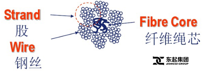
Two or more wires concentrically laid around a center wire is called a strand. It may consist of one or more layers. Typically, the number of wires in a strand is 7, 19 or 37. A group of strands laid around a core would be called a cable or wire rope. In terms of product designation, 7 strands with 19 wires in each strand would be a 7×19 cable: 7 strands with 7 wires in each strand would be a 7×7 cable.
Materials Different applications for wire rope present varying demands for strength, abrasion and corrosion resistance. In order to meet these requirements, wire rope is produced in a number of different materials.
Stainless Steel This is used where corrosion is a prime factor and the cost increase warrants its use. The 18% chromium, 8% nickel alloy known as type 302 is the most common grade accepted due to both corrosion resistance and high strength. Other types frequently used in wire rope are 304, 305, 316 and 321, each having its specific advantage over the other. Type 305 is used where non-magnetic properties are required, however, there is a slight loss of strength.
Galvanized Carbon Steel This is used where strength is a prime factor and corrosion resistance is not great enough to require the use of stainless steel. The lower cost is usually a consideration in the selection of galvanized carbon steel. Wires used in these wire ropes are individually coated with a layer of zinc which offers a good measure of protection from corrosive elements.
Cable Construction The greater the number of wires in a strand or cable of a given diameter, the more flexibility it has. A 1×7 or a 1×19 strand, having 7 and 19 wires respectively, is used principally as a fixed member, as a straight linkage, or where flexing is minimal.
Selecting Wire Rope When selecting a wire rope to give the best service, there are four requirements which should be given consideration. A proper choice is made by correctly estimating the relative importance of these requirements and selecting a rope which has the qualities best suited to withstand the effects of continued use. The rope should possess:Strength sufficient to take care of the maximum load that may be applied, with a proper safety factor.
Strength Wire rope in service is subjected to several kinds of stresses. The stresses most frequently encountered are direct tension, stress due to acceleration, stress due to sudden or shock loads, stress due to bending, and stress resulting from several forces acting at one time. For the most part, these stresses can be converted into terms of simple tension, and a rope of approximately the correct strength can be chosen. As the strength of a wire rope is determined by its, size, grade and construction, these three factors should be considered.
Safety Factors The safety factor is the ratio of the strength of the rope to the working load. A wire rope with a strength of 10,000 pounds and a total working load of 2,000 pounds would be operating with a safety factor of five.
It is not possible to set safety factors for the various types of wire rope using equipment, as this factor can vary with conditions on individual units of equipment.
The proper safety factor depends not only on the loads applied, but also on the speed of operation, shock load applied, the type of fittings used for securing the rope ends, the acceleration and deceleration, the length of rope, the number, size and location of sheaves and drums, the factors causing abrasion and corrosion and the facilities for inspection.
Fatigue Fatigue failure of the wires in a wire rope is the result of the propagation of small cracks under repeated applications of bending loads. It occurs when ropes operate over comparatively small sheaves or drums. The repeated bending of the individual wires, as the rope bends when passing over the sheaves or drums, and the straightening of the individual wires, as the rope leaves the sheaves or drums, causing fatigue. The effect of fatigue on wires is illustrated by bending a wire repeatedly back and forth until it breaks.
The best means of preventing early fatigue of wire ropes is to use sheaves and drums of adequate size. To increase the resistance to fatigue, a rope of more flexible construction should be used, as increased flexibility is secured through the use of smaller wires.
Abrasive Wear The ability of a wire rope to withstand abrasion is determined by the size, the carbon and manganese content, the heat treatment of the outer wires and the construction of the rope. The larger outer wires of the less flexible constructions are better able to withstand abrasion than the finer outer wires of the more flexible ropes. The higher carbon and manganese content and the heat treatment used in producing wire for the stronger ropes, make the higher grade ropes better able to withstand abrasive wear than the lower grade ropes.
Effects of Bending All wire ropes, except stationary ropes used as guys or supports, are subjected to bending around sheaves or drums. The service obtained from wire ropes is, to a large extent, dependent upon the proper choice and location of the sheaves and drums about which it operates.
A wire rope may be considered a machine in which the individual elements (wires and strands) slide upon each other when the rope is bent. Therefore, as a prerequisite to the satisfactory operation of wire rope over sheaves and drums, the rope must be properly lubricated.
Loss of strength due to bending is caused by the inability of the individual strands and wires to adjust themselves to their changed position when the rope is bent. Tests made by the National Institute of Standards and Technology show that the rope strength decreases in a marked degree as the sheave diameter grows smaller with respect to the diameter of the rope. The loss of strength due to bending wire ropes over the sheaves found in common use will not exceed 6% and will usually be about 4%.
The bending of a wire rope is accompanied by readjustment in the positions of the strands and wires and results in actual bending of the wires. Repetitive flexing of the wires develops bending loads which, even though well within the elastic limit of the wires, set up points of stress concentration.
The fatigue effect of bending appears in the form of small cracks in the wires at these over-stressed foci. These cracks propagate under repeated stress cycles, until the remaining sound metal is inadequate to withstand the bending load. This results in broken wires showing no apparent contraction of cross section.
Experience has established the fact that from the service view-point, a very definite relationship exists between the size of the individual outer wires of a wire rope and the size of the sheave or drum about which it operates. Sheaves and drums smaller than 200 times the diameter of the outer wires will cause permanent set in a heavily loaded rope. Good practice requires the use of sheaves and drums with diameters 800 times the diameter of the outer wires in the rope for heavily loaded fast-moving ropes.
It is impossible to give a definite minimum size of sheave or drum about which a wire rope will operate with satisfactory results, because of the other factors affecting the useful life of the rope. If the loads are light or the speed slow, smaller sheaves and drums can be used without causing early fatigue of the wires than if the loads are heavy or the speed is fast. Reverse bends, where a rope is bent in one direction and then in the opposite direction, cause excessive fatigue and should be avoided whenever possible. When a reverse bend is necessary larger sheaves are required than would be the case if the rope were bent in one direction only.
Stretch of Wire Rope The stretch of a wire rope under load is the result of two components: the structural stretch and the elastic stretch. Structural stretch of
Present multi-strand wire rope; No matter be 18 * 7,18 * 19 or 34 * 7,35W * 7 all are to adopt layering to twist with the fingers the production method of system, need use the Bunching machine of 12~18 I-beam wheel during the outer rope of the system of twisting with the fingers, the amount of taking up of the Bunching machine I-beam wheel of 12~18 I-beam wheel has certain limit; The section chief"s degree that can produce is different with the diameter of steel wire rope; The diameter of steel wire rope is big, and then taking up length will lack, and the little length that then takes up of the diameter of steel wire rope just can be longer.To exceeding the steel wire rope that I-beam wheel takes up admissible length, will select the equipment of bigger specification, and the equipment of big I-beam wheel generally has only 6 or 8 I-beam wheel, satisfied not the requirement of I-beam wheel quantity again.
Use conventional methods the production multi-strand wire rope, can length of steel wire rope is restricted,, satisfied not client"s demand, influence economic benefit of enterprises simultaneously when the amount of taking up that has exceeded laying-up reel just can not be produced owing to the size of equipment.
Therefore when production overlength multi-strand wire rope,, then the son rope is housed in the big I-beam wheel the first synthon rope of per two personal shares.The son rope is the basis that produces the outer rope of multi-strand wire rope, and the lay pitch is an important parameter of Wire Rope Production, and this parameter standard still is that rules all only provide a higher limit; Be that the lay pitch is not more than a certain numerical value; The size of the lay pitch is confirmed by adjusting the Bunching machine gear ratio in the production, that is to say that the transmission speed ratio that guarantees the production of son rope is identical with the transmission speed ratio of outer rope, promptly removes a position consistency; The son rope lay pitch of producing like this exists error bigger with the outer rope lay pitch; The adjustment lay pitch that need not stop during production, not only production efficiency is low, and has a strong impact on the steel wire rope quality.
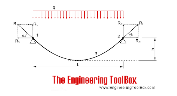
After obtaining the integral solution of formula (1) and considering the boundary conditions (x = 0, y = 0) and (x = l, y = h), the catenary cable shape can be obtained as follows.
In the formula, the parameter \(a = arsh\left[ {\frac{qh}{{2H \cdot \backslash sh\left( {\frac{ql}{{2H}}} \right)}}} \right] + \frac{ql}{{2H}}\) can be obtained by integrating the length s of the catenary cable from Eq. (3) as follows.
From Eqs. (2) to (6), it can be seen that given the tension T of one end cable, the horizontal component H and the cable shape y are coupled with each other. Thus, the unstressed cable length S0 can be determined by iterative calculation. In the calculation, the iterative parameter can be selected as the horizontal component force H, and its initial iterative value H0 is often taken as the component force of the tower end cable tension T along the chord line.
The approximate analytical algorithm assumes that the load and deformation of several main cables of the cable bridge are uniform, and it is equivalent to a single cable plane model, as shown in Fig. 1. It is assumed that the cable shape of the main span is parabolic, and both ends are hinged at the theoretical intersection points A and B of the main cable axis at the saddle. The influence of the horizontal dip angle and the sag of the main cable of the anchor span was ignored, and a horizontal cable force was used to replace the axial cable force of all sections of the anchor cable span and main span. Based on the relationship between the mechanical balance and the physical properties of the materials, according to the geometric conditions of equal cable suspension speed of the whole cable for the same cable bridge under any two load conditions, a cubic algebraic equation of horizontal cable force under the calculated load state is obtained. Finally, the main cable shape is obtained from the obtained balance conditions of the horizontal cable force and moment [11].
Original equipment wire rope and replacement wire rope must be selected and installed in accordance with the requirements of this section. Selection of replacement wire rope must be in accordance with the recommendations of the wire rope manufacturer, the equipment manufacturer, or a qualified person.
Wire rope design criteria: Wire rope (other than rotation resistant rope) must comply with either Option (1) or Option (2) of this section, as follows:
Option (1). Wire rope must comply with section 5-1.7.1 of ASME B30.5-2004 (incorporated by reference, see § 1926.6) except that section"s paragraph (c) must not apply.
Option (2). Wire rope must be designed to have, in relation to the equipment"s rated capacity, a sufficient minimum breaking force and design factor so that compliance with the applicable inspection provisions in § 1926.1413 will be an effective means of preventing sudden rope failure.
Type I rotation resistant wire rope ("Type I"). Type I rotation resistant rope is stranded rope constructed to have little or no tendency to rotate or, if guided, transmits little or no torque. It has at least 15 outer strands and comprises an assembly of at least three layers of strands laid helically over a center in two operations. The direction of lay of the outer strands is opposite to that of the underlying layer.
Type II rotation resistant wire rope ("Type II"). Type II rotation resistant rope is stranded rope constructed to have significant resistance to rotation. It has at least 10 outer strands and comprises an assembly of two or more layers of strands laid helically over a center in two or three operations. The direction of lay of the outer strands is opposite to that of the underlying layer.
Type III rotation resistant wire rope ("Type III"). Type III rotation resistant rope is stranded rope constructed to have limited resistance to rotation. It has no more than nine outer strands, and comprises an assembly of two layers of strands laid helically over a center in two operations. The direction of lay of the outer strands is opposite to that of the underlying layer.
Type I must have an operating design factor of no less than 5, except where the wire rope manufacturer and the equipment manufacturer approves the design factor, in writing.
A qualified person must inspect the rope in accordance with § 1926.1413(a). The rope must be used only if the qualified person determines that there are no deficiencies constituting a hazard. In making this determination, more than one broken wire in any one rope lay must be considered a hazard.
Each lift made under § 1926.1414(e)(3) must be recorded in the monthly and annual inspection documents. Such prior uses must be considered by the qualified person in determining whether to use the rope again.
Rotation resistant ropes may be used as boom hoist reeving when load hoists are used as boom hoists for attachments such as luffing attachments or boom and mast attachment systems. Under these conditions, all of the following requirements must be met:
The requirements in ASME B30.5-2004 sections 5-1.3.2(a), (a)(2) through (a)(4), (b) and (d) (incorporated by reference, see § 1926.6) except that the minimum pitch diameter for sheaves used in multiple rope reeving is 18 times the nominal diameter of the rope used (instead of the value of 16 specified in section 5-1.3.2(d)).
The operating design factor for these ropes must be the total minimum breaking force of all parts of rope in the system divided by the load imposed on the rope system when supporting the static weights of the structure and the load within the equipment"s rated capacity.
Wire rope clips used in conjunction with wedge sockets must be attached to the unloaded dead end of the rope only, except that the use of devices specifically designed for dead-ending rope in a wedge socket is permitted.
Prior to cutting a wire rope, seizings must be placed on each side of the point to be cut. The length and number of seizings must be in accordance with the wire rope manufacturer"s instructions.

Deep resource extraction is an effective method for today’s energy crisis, and it is also an important strategic goal of China [1,2]. Deep resource mining relies on the safe work of mine hoists. For mine hoists where rope hoisting is dominant, the failure of rope arrangement is an important factor affecting the safe and stable operation of hoists [2]. For ultra-deep mines, high speed and heavy load will be common conditions, which generally means that a thicker and longer wire rope is required. This can lead to the width of the rope winding area of the drum and the number of layers of wire rope on the drum increasing. Then, the possibility of rope winding errors is larger, and the risk is greater, making the rope fault detection a problem that must be solved for the ultra-deep mine hoist. However, currently, the detection of the status of the rope arrangement mostly relies on manual inspections or manual guards. The rope tension sensors and displacement transducer installed on the wire rope or drum can tell us some signs of the rope arrangement status, but it is not direct enough, easy to be disturbed, with low accuracy and is unable to find the rope arrangement fault in time. Therefore, a sensor or a detection method for accurate full-time automatic detection of the rope arrangement state is very necessary.
At present, machine vision is increasingly being used for the testing and calculation of specific targets in large-scale projects, and has achieved good results. Such as the calculation and measurement of large-scale structural parts [3], the calculation of the vibration mode of cable-stayed bridges [4,5], and the deformation monitoring [6,7] and geometric shape detection [8] of bridge structures. Using machine vision to detect the status of the wire rope is becoming an effective method.
In the use of machine vision to detect the position of the wire rope, Chen et al. [9] use a customer grade camcorder and an ordinary tripod to detect the frequency of steel wire ropes on a cable-stayed bridge, achieving the same order of accuracy for cable frequency identification as that of high-resolution velocimeters. Winkler et al. [10] use digital image correlation to obtain measurement of local deformations in steel mono strands. Yao et al. proposed a non-contact video-based measurement for transverse displacements of hoisting catenaries in mine hoist using mean shift tracking [11,12] and digital image processing techniques [13]. Wu et al. [14] proposed a non-contact and unmarked machine vision measurement method for measuring the transverse vibration displacement of hoisting vertical ropes. In the hoisting cape area, because the video of the rope detection is shot with the sky as the background, the target and the background are very distinguishable, so the recognition effect is obvious, and the background of the wire rope to be detected in the reel area is the same wire rope (such as Figure 1a) and the target and the background are very similar, thus the same recognition method will be much worse.
Flowchart of the rope arrangement detection method based on optical projection and machine vision. (a) Take a video of the rope arrangement projection, (b) the image of projection area in each frame is binarized, (c1) extracting edge curve of graph (b), (c2) smoothing the edge curve of graph (c1), (d) feature extraction, (e) clustering, assessment and obtain the results.
Table 1 shows the current existing detection methods for rope arrangement detection. Wu et al. [15] used the method of adaptive gray threshold segmentation on the same horizontal line to achieve the distinction between the target wire rope and the background, but this method is based on the difference in the reflective performance of the wire rope and the rope groove. For the oily wire rope, the tightly wound wire rope and multi-layer steel wire rope on the drum are not applicable. Xue et al. [16] proposed the method of using template matching and limiting the size of the target selection area making the target and the background better to distinguish, and realized the video tracking of the position of the wire rope. Other video tracking methods, like KCFs (kernelized correlation filters) [17] and Staple [18], can be used for rope arrangement detection. However, because the target selection area is limited, the algorithm is easy to lose the target when the rope winding speed is fast or the skipping span is large. At the same time, when shooting a wide reel, the image will inevitably be distorted (as shown in the Figure 1a). In addition, because the target is deformed greatly, part of the texture information is lost and cannot be retrieved through distortion correction, thus the video tracking of the position of the wire rope is very difficult. To sum up, the difficulties of rope detection in ultra-deep mine hoist based on machine vision are summarized as follows:The target is extremely similar to the background;
Therefore, this study aims at detecting and diagnosing the problems of rope arranging faults in ultra-deep mines with wide drums and high speeds, and proposes a new method for arranging rope detection based on machine vision and optical projection. In this study, edge projection image is used to detect the state of rope arrangement to make the rope separated from its complicated and similar background. Using approximate parallel light irradiation and quantitative calculating, the installation position of the point light source required by the drum, with different widths to solve the problem of distortion of the wide reel, is found. For higher detection speed and more accurate detection results, unlike other video tracking methods that require a comparison of several frames, we get the rope arrangement at that moment with just the current single frame and consider the detection results of current frames to judge the rope arrangement fault. In both the laboratory and the simulation test bed, the purpose of error-free identification of the rope fault is achieved, and the processing speed exceeds 150 fps (for narrow reels, it can reach 300 fps or more).
The flow of the novel method is shown in Figure 1. First, illuminate the edge of the reel rope with parallel light, place a pure white background board at its projection position, then use an industrial camera to shoot the projection of the rope on the background board, process the projected image, and extract the characteristic value corresponding to each wire rope. Finally, the unsupervised clustering method is used to classify and get the rope status detection result.
The arrangement of this paper is as follows: At present, there are few introductions of the reel-rope projection model, which has a greater impact on the setting of the relevant parameters of this study. Therefore, this article will describe (in Section 2) how to choose the drum-rope projection model and the installation position of the point light source, (in Section 3) how to quickly obtain the boundary curve from the binarized image and then extract the feature value to ensure that each feature value corresponds to a wire rope or a rope groove; and (in Section 4) how to use the unsupervised clustering method for such features’ values for effective and robust classification. And in Section 5, the application effects in the model machine and the real mine are described.
dist()A function to calculate the distancerThe radius of the section circle of torus or the radius of the ropeHlightThe installation height of the point light source
Wire rope is widely used in mining operations due to its high strength, light weight, and good elasticity [1,2]. However, the degree of damage sustained by the wire rope increases considerably with the increase in the usage time and due to the increase in the long-term impact of factors such as tensile bending, alternating loads, and the environment. Furthermore, this damage is inevitable if it is not addressed in time, and it can adversely affect the productivity of mining operations and threaten the safety of both the personnel and the equipment. Coal mine safety regulations have been established to ensure the productivity of mining operations; according to these regulations, mining hoist ropes must be tested every day and their scrap period is two years. If the degree of damage does not exceed the relevant provisions, their usage can be extended by no more than one year.
Various methods have been proposed for the non-destructive testing of wire ropes. Most of the current studies are focused on methods such as ultrasonic detection [3], electromagnetic detection [4], X-ray detection, and magnetostriction [5], as well as eddy current, current, and vibration detection [6,7]. The electromagnetic detection method is the most widely implemented method, owing to its demonstrated reliability and practicality. The basic principle of the electromagnetic-based leakage detection method used in this study is shown in Figure 1. The permanent magnet magnetizes the wire rope to saturation, forming a closed magnetic circuit among the wire rope, magnet, and yoke. In the presence of a damage, the original magnetic induction lines through the wire rope form a closed magnetic circuit in the air and generate a leakage magnetic field.
When using the electromagnetic detection method to detect leakage, the wire rope detection signal is mixed with a variety of sources of interference noise, including the spiral structure of the wire rope, which produces periodic changes in the strand noise; the detection of the magnetic field in an environment of complex and variable high-frequency low-amplitude noise; the shaking of the wire rope during the operation process, producing low -frequency random noise; electromagnetic interference issuing from the electromagnetic detection circuit; detection line voltage jitter; drift; and other sources of noise, all of which affect the accurate judgment of the leakage signal. To address the aforementioned challenges, Peng, F. et al. [8] applied a multi-stage filtering method based on EEMD and optimal wavelets in three-dimensional UME signal processing to effectively suppress noise interference. Zhang, J. et al. [9] proposed a new filtering system consisting of the Hilbert yellow transform and compressive-aware wavelet filtering to denoise strand and high-frequency noises. Furthermore, Chun et al. [10] designed a filter based on the multi-stage wavelet analysis of a time-domain-reflection method. Moreover, they effectively eliminated the wild-point noise and industrial frequency interference noise. The abovementioned wire rope damage signal has been studied extensively. However, because the effect of wavelet packet decomposition depends on the choice of the wavelet basis function and the number of decomposition layers, it is not an adaptive signal decomposition method. In recent years, EMD has been widely used in mechanical fault diagnosis. However, owing to the existence of endpoint effects and modal confusion, this algorithm needs to be further studied. To address the limitations of EMD and WT, Dragomiretskiy et al. [11] proposed a new adaptive time-frequency analysis method called VMD in 2014. Compared with EMD and AWT, VMD can suppress interference signals, prevent the loss of useful information, and provide a high-quality data source for subsequent feature extraction. Moreover, it has high decomposition accuracy and operational efficiency and can effectively suppress the overlap mode in a signal decomposition process.
Wire rope detection is challenging because of signal noise reduction, as well as the difficulties involved in achieving a quantitative detection process following noise reduction, owing to the complex structure, shape, and location of the wire rope, which itself produces different types of defects. To solve this problem, some scholars have conducted representative studies. Li, J. et al. designed a nondestructive wire rope inspection device which used double detection plates to collect MFL data, improved the image resolution based on a super-resolution algorithm, and finally used the AdaBoost classifier to classify the defect images [12]. Zhang, J. designed a device based on a residual magnetic field device, proposing a novel filtering system to improve the signal-to-noise ratio, and at the same time used digital image processing techniques to achieve the quantitative recognition of defect images [13,14]. Tan, X. proposed a novel test structure with a huge array of magnetoresistive sensors to effectively identify multiple types of damage and finally applied radial basis neural networks for the quantitative recognition of magnetic images [15]. W Sharatchandra Singh et al. designed an ultrasonic sensor to detect wire rope damage signals by means of ultrasonic detection method and conducted quantitative recognition research using a BP neural network [16]. Artificial neural networks and related algorithms have contributed significantly to the field of pattern recognition. However, their recognition performance is significantly influenced by several parameters and can easily fall into a local minima in the optimization process. However, SVMs have few adjustable parameters and stable operation [17]. Thus, with fewer training samples, higher diagnostic accuracy can be achieved. Therefore, in this study we used SVMs based on PSO for the identification of internal and external wire rope damages.
In summary, it is difficult to detect the internal damage of wire ropes using the existing flaw detection equipment. Therefore, we have designed a wire rope detection device based on leakage magnetism. The detection device is implemented using permanent magnets to magnetize the wire rope, axial, and radial magnetization sensors in order to obtain the wire rope defect information. At the same time, the mapping relationship between internal damage and external damage was analyzed using the finite element method to prepare for the experiment. The VMD-AWT noise reduction method is used to reduce the noise of the original signal and calculate the wavelet information entropy based on the reconstructed signal to construct a multidimensional feature vector. Finally, the PSO-SVM algorithm is proposed to effectively and quantitatively classify and identify the internal and external defects of the wire rope using a multi-dimensional feature vector dataset.

This paper is mainly aimed at 0.28 + 6 × 0.26 steel cords and 0.26 + 6 × 0.24 steel cords under different lay length conditions through the ABAQUS finite element analysis software to limit the tensile performance of the steel cord and the stress field distribution during the tensile loading. Based on the finite meta-analysis, in this experiment, the tensile simulation of the same kind of steel cord at the twist lay length of 5 mm, 7 mm, 9 mm, 11 mm, 13 mm, and 15 mm was carried out under the condition of 2 mm/s. The results show that, under certain conditions of other process conditions, with the increase of the twisting distance of the steel cord strands, the strength of the steel cord increases, the deformability decreases, the stress concentration decreases, and the spinning loss decreases. The spinning loss formula is modified to reduce the calculation error.
Steel cords are usually used as meridian tire skeleton structures and play an important role in improving tire strength, performance, and service life [1–3]. As a meridian tire skeleton structure, the performance of steel cords is critical for meridian tires, so the improvement of steel cord performance is also the focus of close attention of related enterprises [4–6]. Steel cord originated in the steel wire rope cable and other industries, in the processing process and structure there is a certain similarity.In the development of steel cord, steel cord to repeated experiments and other ways to obtain the optimal structural parameters, so the experimental direction is poor, consumption time is longand results in waste of resources [7–9]. Finite element analysis is widely used in mechanical structural analysis and has a more intuitive and obvious effect on stress analysis of complex structural metal products such as steel cords.
In 2003, Wang et al. [10, 11] derived the structural parameter equation of the secondary twisted steel cord based on the Frenet–Serret formula. From 2010 to 2011, Erdonmez and Imark [12–14] used MATLAB computer language to complete the modeling of the primary and secondary twisting structures of steel cords by means of codes, and combined HyperMesh and ABAQUS software for mesh rendering and mechanical finite element analysis. Wang et al. [15, 16] summarized three modeling methods including three-dimensional drawing software and modeling equation combined modeling, using the sweeping method for modeling, and mathematical software combined with three-dimensional drawing software modeling. Then, the data envelopment analysis method was introduced into the steel cord modeling analysis. In 2017, Xiang et al. [17] used 3D digital image correlation (3D∼DIC) technology to extract surface stress and strain data of steel cords and found that the rotation and restriction of both ends of the steel cord would increase the contact stress between strands. In 2018, Long et al. [9] analyzed the factors affecting the steel cord conveyor belt and analyzed the influence of different positions and arrangement sequences of the steel cord in the conveyor belt on the strength of the contact interface between the steel cord and the rubber. The pulling force is slightly greater than the edge position. The drawing force increases nonlinearly with the increase in the number of strands. In 2019, Li et al. [18] analyzed the influence of steel cord length, wire diameter, rubber thickness, and the number of internally distributed steel cords on the drawing force of the steel cord conveyor belt joint. Among them, the strength of steel cord length and diameter of the influence is closer to linearity, and the influence of the number of steel cords on the strength of the joint shows a nonlinear increase. In 2021, Olchówka et al. [19] used the DiagBelt system to scan two-dimensional images of magnetic field changes around faults to identify defects in steel cord production and applied artificial intelligence methods to build multilayer neural networks (MLP) and teach them appropriate damage recognition. This analysis can determine the Pearson linear correlation coefficient between the parameter being changed and the fault image.
In this paper, the finite element method is used to determine the internal stress distribution and spinning loss state of the steel cord under different lay length conditions to improve the performance of the steel cord. It is attempted to analyse the force distribution of steel cord core and surface strands and the trend of maximum load through ABAQUS finite element analysis software for the stretch load of steel cords under different lay length conditions. The steel cord model is made of 0.28 + 6 × 0.26 (0.28 mm diameter single wire with 6 surface strands, 0.26 mm diameter monofilament) steel cord, and 0.26 + 6 × 0.24 (center strand is 0.26 mm diameter monofilament, surface strands of the wire is 6 0.24 mm diameter single wire) steel cord, through the ABAQUS software model building module for steel cord 3D model drawing and the use of ABAQUS finite element analysis section for 0.28 + 6 × 0.26 steel cord and 0.26 + 6 × 0.24 steel cord at 2 mm/s stretch simulation under conditions.
The material mechanics performance test of the single wire that makes up the steel cord is carried out to provide the parameters required for the simulation and to verify the accuracy of the simulation process method. The 6 sets of finite element analysis tests with different spacing of 0.26 + 6 × 0.24, 0.28 + 6 × 0.26 are then carried out to analyse the effect on the stretching performance of steel cords with the change of steel cord lay length, as shown in Figure 1.
The steel cord structure usually contains a wire strand structure with one, two, three, or even multiple twists [20], and this experiment mainly analyses one of the strands in detail, and the main involved structural form can be determined by the following parameters, including the steel cord core single wire radius r0, the face single wire radius r1, the tingling radius R, and the lay length P, as shown in Figure 2 [21–24]. Wherein in the simulation process, 0.28 + 6 × 0.26 steel cord core single wire diameter r0 = 0.28 mm, r1 = 0.26 mm, the twisting radius R = 0.27 mm, the center line length S = 20 mm, and 0.26 + 6 × 0.24 steel cord core single wire diameter r0 = 0.26 mm, r1 = 0.24 mm, the twisting radius R = 0.25 mm, centerline length S = 20 mm, lay length is, respectively, set to P = 5 mm, 7 mm, 9 mm, 11 mm, 13 mm, and 15 mm for comparative testing.
The stretching simulation of steel cords in finite element analysis software involves only one-time twist structure, so the model uses only one-time fabric model building blocks in ABAQUS finite element analysis software and can build the required models and assign material properties required for stretch analysis of the model cross section, including material density and single-wire elasticity of different silk diameters (Yang’s modulus, Poisson ratio), and plasticity (plastic strength, plastic deformation). In order to make the steel cord finite element analysis process consistent with the steel cord tensile performance test process as much as possible, a 5 mm length MPC constraint (beam) was applied to both ends of the steel cord through the reference point, and according to the tensile test process, using a dynamic explicit analysis step, a completely fixed boundary condition is applied to one end of the rope, and the other end is stretched at a constant speed of 2 mm/s in the stretching direction.
The main mechanical properties of steel cords are shown in the ability to withstand pull out in order to perform mechanical finite element analysis on the steel cord model; therefore, the mesh type uses a 3D stress mesh (C3D8R: an 8 node linear brick, reduced integration, and hourglass control), and steel cord is a spiral cylindrical structure. Common element shapes such as hexahedron, tetrahedron, and wedge-shaped mesh can effectively divide the steel cord model. In order to make the finite element analysis more efficient, this experiment mainly uses hexahedral mesh. The model, standard element library, and linear geometric order analysis are divided because of the randomness of the steel cord break cross-sectional position, so the mesh seed is evenly distributed in the direction of stretching, and each layer section evenly distributed hexagonal mesh 32 units, as shown in Figure 3.
Material selection: 72A material, material properties related to density: 7.81E-09 tonne/mm3, Young’s modulus: 206000 MPa, Poisson’s datio: 0:3, and Φ0.24 mm, Φ0.26 mm, and Φ0.28 mm steel cord single wire stretch stress strain curve and break force are determined by stretch testing. The tested single-wire stretching performance is shown in Table 2 below, and the stress-strain curve is shown in Figure 4 below, and then, the material properties are attached to the model cross section to complete the granting of material properties.
2 mm/s speed stretch simulation of Φ0.24 mm, Φ0.26 mm, and Φ0.28 mm steel cord single wire of steel cord was used to obtain the steel cord simulation break force, tensile strength, and total elongation, as shown in Table 3 below. By comparing Table 2 with Table 3, it can be seen that the stretch properties of steel cords obtained from the simulation results are the same as the actual measurements, which also shows that the test scheme; that is, the different lay lengths carried out by ABAQUS finite element analysis software are 0.26 + 6 × 0.24 steel cords and 0.28 + 6 × 0.26 steel cords. The finite element analysis process has a certain degree of authenticity and reliability.
The difference between the actual strength value of the processed steel cord and the expected strength value is called spinning loss, and the commonly used calculation formula isη: loss/% F0: core stock single wire break force/N. F1: face stock single wire break force/N. n: face share single silk quantity. F: steel cord break force/N.
The results of the simulation of 0.26 + 6 × 0.24 steel cords and 0.28 + 6 × 0.26 steel cords at different lay length are calculated by formula (1) As shown in Figure 8, when the steel cord lay length increases the spinning loss of steel cord slinging and the increase in the margin is inversely proportional, with the increase of the lay length, the spinning loss of the steel line is on a downward trend, the lay length is lower than 9 mm the decline trend is larger, higher than 9 mm when the downward trend gradually slows down.
Steel cord surface strands are spiral like and therefore more complex force faces stock line. Single wire tension F1 direction is the center line direction of the face stock, which can be broken down into vertical in the center direction of the face stock force N, shear force, and stretch direction of τ and axial force Fδ, as shown in Figure 9 below, wherein the stock edge angle and the ring length of the αmargin P, radius R formed by the triangular function relationship can be calculated by the formula corner size; the formula is as follows:
Steel cord load F is mainly composed of core stock strand tension F0, face stock strand tension axial split force Fδ, shear force N, and torque τ and axial split force F1, the main formula is
By the refined loss formula, the 0.26 + 6 × 0.24 steel cord and 0.28 + 6 × 0.26 steel cord stretching simulation experimental results were calculated, and the loss of the tanning system was greatly reduced, and the comparison of the original results was negligible, as shown in Figures 10 and 11 below.
The lay length is one of the most important factors affecting the tensile properties of steel cords. This article is mainly based on other scholars’ research on steel cord modeling and adjusts and studies the process parameters in steel cord production through finite element analysis. Based on the finite element analysis, the steel wire used in the steel cord and the finished steel cord with 7 mm lay length passed the finite element analysis results and the experimental test results. By comparison, the accuracy of the value was verified, and the tensile finite element analysis of two types of steel cords with different lay lengths was carried out to determine the influence of the lay length on the performance of the steel cord. With the increase of the lay length, the steel curtain of the wire breaking force is increased, the stress concentration is gradually reduced, and the cross-sectional stress distribution of the steel cord is more uniform. However, the upward trend has gradually slowed down. It can be seen that increasing the twist pitch of steel cords can improve the overall performance of steel cords to a certain extent, but the two are not linear. The above conclusions are not only for the choice of twist pitch process parameters in production but it plays an auxiliary role with adjustment and also plays a guiding role in the research of other production process parameters of steel cord, such as the diameter of different strands and the cross-sectional shape of strands.

Wire ropes are largely used in marine environment or for rigging purposes. They receive considerable loads and thus suffer a great deal of mechanical damage throughout their service life. Moreover, research has shown that the major cause of wire rope failure is excessive deterioration and corrosion, lack of maintenance and inspection, and wrong usage resulting in early discarding, reduced safety and replacement cost increase.
Sometimes damage can be easily detected, while in other cases fractured wires may occur on the inside. Hence, wire ropes should be inspected and maintained by the right person (competent person assigned by the company), to assure they’re in perfect condition. Regular inspectionsensure high rope performance, long service lifetime , safety of personnel and equipment, and reduced operating costs.
All ropes (synthetic, high modulus and wire ropes) should be inspected before and after an operation. This guideline ensures maximum safety for both a ship’s personnel and equipment. Even though it’s difficult to determine the exact service life span of ropes, there is a way to have a more precise estimation about their efficient lifecycle. Calculating the exact time ropes have been in use (e.g mooring time, mooring conditions, weather and tidal conditions) is the answer. All in all, rope inspections should occur at least once a year.
Inspecting wire ropes in particular, comes with great responsibility. Inspection results should be recorded, and any defects noticed have to be reported and addressed properly. Some defects can be repaired, while in some cases replacing a wire rope is inevitable.
Periodical inspections ofvessel deck equipment is also crucial for maintaining the good condition of wire ropes. The condition of the drum, chocks, bitts, rollers, sheaves, cable clamps and other end fittings, affect the rope’s performance, threads and cords. Make sure to mark these parts during your overall inspection.
In order to help marine officers and staff conduct successful wire rope inspections – and keep an up-to-date record of them – we have created an inspection solution that helps in maintaining and monitoring a ship’s ropes and deck equipment.
When calculating mass using F = Minimum Breaking Force, according to the wire rope’s diameter, you can determine the Minimum Breaking Massand therefore the wire’s max strength. When calculating mass using F = Safe Load according to the wire rope’s diameter, you can determine the Safe Load Mass,which is the advised load for this rope diameter.
The strands of a wire rope absorb the majority of the tensile force applied on the rope. Their design and manufacturing standards affect the level of fatigue resistance and resistance to abrasion. An easy way to understand which rope design is suitable for each purpose, is the wire rope classification.
Wire ropes are classified according to the number of strands in each construction and the number of wires in each strand. For example, a classification of 6X19 means that a wire rope of this type always has six strands, but its wires could be 15-26 per strand. This is because 19 is not the exact number of wires, but the classification of a wire number range.
Visual inspections are a common and fast way to assess wire rope condition. Both the standard and rotation resistant wire rope inspectionprocesscomply with the same four steps of examination. A ship’s crew can perform them as follows:
Steel wire rope distortion is obvious in most cases and can easily be identified by the inspector or the ship‘s crew. It usually occurs if load is suddenly applied or abruptly released (shock loading), or even if swift torque is forcefully induced.
Although not all of these deformations make the rope absolutely dangerous to use, they all may cause ropes to wear unevenly in time. This means inspections should take place more often, and distorted ropes should be handled with caution.
The rag and visual inspection is a good method for regular inspection intervals. The inspector pulls a rag along the rope trying to find broken wire cords. If the rug gets snagged by the rope, the inspector has to stop and assess the wire rope’s condition. Extreme caution should be exercised during the visual inspection, and under no circumstances should this method be the only one used to inspect wire ropes.
Tip: When you encounter a protruding wire end, bend it back and forth manually, until it separates from the wire. This will protect neighboring wires from wearing out.
Diameter reduction is a critical factor in steel wire rope wear and if not properly taken care of, it can result in rope breakage. Excessive abrasion, loss of core mass, corrosion or inner wire failure are all factors that contribute to diameter reduction.
To get an accurate measurement of the rope’s diameter, measure the rope at three different points at least 5 feet apart. Take the average of these three measurements to determine the true diameter.
Any measurements showing a reduction of ⅓ or more, indicate that a replacement should follow without delay. A diameter reduction of less than 1/3 still requires attention, and the inspector or the ship’s crew should be on guard in the next scheduled wire rope inspection.
Failure from abrasion or corrosion is a result of deficient deck equipment inspection or insufficient wire rope lubrication respectively. Internal corrosive damage is more difficult to identify than any other types of degradation. In most cases, the damage has progressed more than the external signs suggest.
Wire rope storage plays a significant role in the rope’s operation life.Wire rope corrosion and pitting can be avoided if ropes are safely stored in a clean, cool, dry and well-ventilated place. Steel wire ropes should not by any means rest on the floor, and should be protected from water, dust or any chemical fumes. Long term storage requires periodic greasing, turning the reel upside down for preventing grease dripping and possibly re-winding to another reel with larger inner tube diameter.
Wire ropes should be maintained with periodical lubrication. In order to prevent internal corrosion, a pressure lubricator is suggested to be used. In this case, a small amount of grease is used to lubricate the rope internally, while the deck stays grease-clean. Pressure lubricators clean the rope before they grease it so that the new grease enters a clean rope. The type of grease used is very important for maximum protection and greasing efficiency.
Steel wire ropes exposed to dirt, grime and other contaminants, have to be cleaned with a wire brush and petroleum (unless a pressure lubricator is used). Optimal cleaning of wire ropes can extend their service life and guarantee safe operations.
The reeling process is of high importance for the longevity of wire ropes. To protect them from being damaged, it is important that the surface of the drum is clean, smooth and dry. Improper reeling may cause wire-rope strands to spread or get flattened, when in contact with one another, as successive layers are being spooled and upper layers apply pressure on the lower ones.
Katradis S.A. offers a wide range of top quality wire ropes for shipping (mooring and hoisting operations), fishing and construction purposes. Our wire ropes have greater resistance to fatigue, and they distribute tension force equally among the rope strands. They are less likely to kink, providing higher staff safety and assuring operation success.


 8613371530291