
wire rope capacity formula in stock
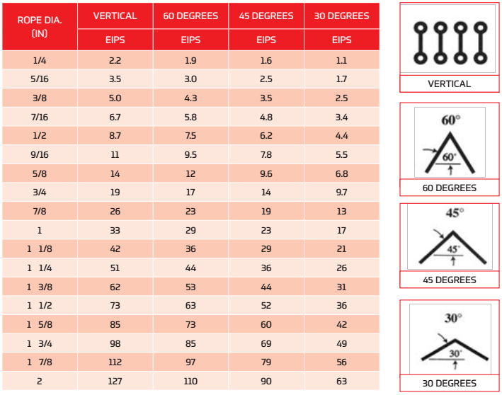
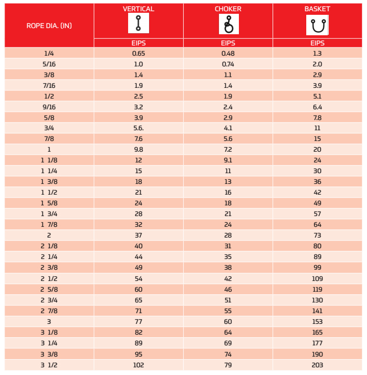
If you are performing calculations involving the load of bridles and basket hitches, it’s important to use a wire rope sling capacity chart and also remember that as a reduction in the horizontal angle of the sling occurs the load imposed upon each leg increases. With bridles consisting of three or more legs, the horizontal angle is measured in the same manner as it is for horizontal sling angles consisting of two legged hitches. Different angles may result if a bridle consists of different leg lengths. The load supported by each leg must be determined based on the location of the center of gravity of the lift in the position of the slings.
At Kennedy Wire Rope & Sling Co., Inc., we provide high quality wire rope sling components and can help you determine the capacity of your wire rope sling arrangement.
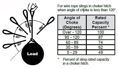
By making an adjustment to the rated capacity of a choker hitch degrees with the body of the sling used in the choke, the rated capacity is reduced. Choker rated capacity tables indicate this reduction. The angle the choke must also be considered when determining reductions in rated capacity.
The standard choke angle is about 135 degrees when a load is hanging free. However, using a choker hitch to lift internal load can produce a significant bend at the choke. It’s important to reduce a hitches rated capacity when it is used at an angle smaller than 120 degrees. As is evident from a wire rope sling capacity chart, the rated capacity of a wire rope sling must be adjusted when using a choker hitch to turn, shifts, or control the load. The rated capacity must also be adjusted when, in a multi-leg lift, the pull is against the choke.
Using choker hitches at angles of 135° or greater is not recommended due to the instability produced with this arrangement. In addition to consulting with a wire rope sling capacity chart, considerable care should also be taken to ensure that the choke angle is determined and applied as accurately as possible.
Wire rope and chain are the important part of the hoist which are closely bound up with the safe work load, now let’s talk about how to calculate the SWL of ropes and chains.
Sticking on national standards, DQCRANES has passed ISO9001 international quality system certification, ISO14004 environment management system certification, OHSA18001 and European CE Certifications which comprehensively promotes overall management level and makes DQCRANES known and welcomed by international customers.
Wire rope is also known by many other names, such as: wire, multi-strand wire, flexible wire, cable, cord, steelcord, etc. but it is essentially a collection of small filaments wound around each other in a manner that largely retains its shape when bent, crushed and/or tensioned.
It is a system for significantly increasing the strength and flexibility of steel wire and is used in almost every important application we see around us. For example: suspension bridges, tyres, brake and accelerator cables (in cars), high-pressure flexible pipes, lifting and rigging cables, electrical conductors, etc. and it comes in many different forms. Fig 2 shows just a very small sample of available designs.
With minor variations, the generally accepted method for designating a wire rope construction in the industry is by describing it numerically. For example:
Whilst "IWRC" wire ropes offer a slightly greater tensile capacity (≈7%) than those with fabric or polymer fillers, the additional strength does not come from the tensile capacity of the core filaments but from improved dimensional stability under load. And whilst they are also much more resistant to crushing, they are stiffer than fibre core ropes and therefore not recommended for applications where tension occurs under bending.
Warrington (Fig 1) is a parallel lay construction with an outer layer comprising wires of alternating large and small diameters, each outer layer having twice the number of wires as the layer immediately beneath. The benefit of this design is to increase packing and therefore strength density, however, unless the different diameter filaments are of the same strength (unlikely), this construction is limited by the strength of the weakest filaments.
Seale (Figs 1 & 2 6x36) is also a parallel lay construction but with the same number of wires in each wire layer. All the wires in any layer are the same diameter. This is an alternative to the Warrington construction, with similar benefits and disadvantages.
Regular lay constructions are used much more widely (than Lang lay) because they have excellent structural stability and less tendency to unwrap under tension (see Rotating vs Non-Rotating below). However, because it has a knobbly (undulating) surface it will wear both itself and any surface over which it is run much more quickly than Lang lay wire rope.
Lang lay constructions have a flatter surface than regular lay constructions giving them better resistance to wear and bending fatigue, especially when made from flattened (elliptical) filaments. They are, however, much less structurally stable and subject to birdcaging if the wire rope is over-bent or twisted against its wrapped direction.
"Regular Lay", multi-strand constructions are normally subject to slightly less rotation under tension (than Lang lay) due to the opposite helical direction of the filaments (within the strands) and the strands (within the rope), however, you can improve their rotation characteristics still further by;
Fillers (Fig 2) may be fabric, polymer or even smaller diameter filaments (e.g. 6x36). Whilst they contribute little to the tensile strength of wire rope, they can significantly; improve performance under bending (fabric and polymer cores only), reduce axial growth, reduce rotation in rotation-resistant constructions, improve structural stability and increase fatigue life.
This filler material should not be included in strength (tensile capacity) calculations, but must be included in those for axial stiffness (extension). If it is ignored, your calculations will reveal excessive extension as the wire rope collapses.
Suspension bridges tend to be constructed from densely packed, single strand plain "Wire Rope" constructions using large diameter galvanised filaments. Little heed is paid to rotational resistance as strength is paramount and once tensioned, they should remain in that loading condition for their design life.
Lifting & winching normally require wire ropes of good flexibility and fatigue resistance. Therefore they tend to be similar to 6x36 but with fibre core instead of the IWRC in Fig 2
Remote operating cables such as hand-brakes and accelerators on cars normally only work in tension so they need to be strong but not necessarily stiff (as they are fully contained in reinforced outer sheaths). These tend to be manufactured from large diameter "TyreCord" or small diameter single-strand "Wire Rope".
Wire rope does not obey Hooke"s law. Therefore, you cannot accurately predict how much it will stretch for any specified force. This unpredictability applies to any section removed from the same manufactured length of cord and even between cords produced to the same specification but by different manufacturers.
CalQlata has decided that the accuracy of axial stiffness (EA) of wire rope falls outside its own levels of acceptability and therefore does not include it in the wire rope calculator. The extension calculated in the Wire Rope calculator (δLᵀ) is based upon the effect of axial tension on packing density. It is therefore important that core material is not ignored when using the calculator to evaluate this characteristic.
Wire rope does not obey Hooke"s law. Therefore, you cannot accurately predict how much it will twist for any specified torque. This unpredictability applies to any section removed from the same manufactured length of cord and even between cords produced to the same specification but by different manufacturers.
CalQlata has decided that the accuracy of torsional stiffness (GJ) of wire rope falls outside its own levels of acceptability and therefore does not include it in the wire rope calculator.
1) No wire rope calculator, whether dedicated or generic, will accurately predict the properties of any single construction under a wide range of loading conditions
2) No wire rope calculator, whether dedicated or generic, will accurately predict any single property for a range of constructions under a wide range of loading conditions
The only wire rope that can be reliably analysed is that which is used for suspension bridges, because; it comprises a single strand, is very densely packed, has negligible twist, contains filaments of only one diameter, is never subjected to minimum bending and every filament is individually tensioned.
There is a very good reason why manufacturers do not present calculated performance data for construction or design proposals, because even they cannot accurately predict such properties and quite rightly rely on, and publish, test data.
During his time working in the industry, the wire rope calculator"s creator has seen, created and abandoned numerous mathematical models both simple and complex. He has gradually developed his own simplified calculation principle based upon his own experience that still provides him with consistently reliable results of reasonable accuracy.
The purpose of CalQlata"s wire rope calculator is to provide its user with the ability to obtain a reasonable approximation for a generic construction, after which, accurate test data should be sought from the manufacturer for the user"s preferred construction.
The calculation principle in the wire rope calculator is based upon changes in the properties of the wire rope that occur with variations in packing density under tension
Bearing in mind the above limitations CalQlata can provide the following assistance when generating (manipulating) the wire rope calculator"s input data and interpreting its output
Alternatively, for wire rope with multiple filament diameters, you need to find an equivalent diameter with the following proviso; you must enter the minimum filament yield stress (SMYS)
It is expected that apart from fillers, all the material in the wire rope will be identical and therefore have the same density, i.e. using different materials will result in less than "best" performance. However, if such a construction is proposed, you can calculate an equivalent density as follows:
It is expected that apart from fillers, all the material in the wire rope will be identical and therefore have the same tensile modulus, i.e. using different materials will result in less than "best" performance. However, if such a construction is proposed, you should enter the highest tensile modulus.
The wire rope calculator simply adds together the total area of all the filaments and multiplies them by the SMYS entered, which represents a theoretical maximum breaking load that would exist if this load is equally shared across all of the filaments and the lay angles have been arranged to eliminate localised (point) loads between adjacent filaments.
If the wire rope has been properly constructed it is likely that its actual break load will be greater than 80% of this theoretical value. However, given the vagaries of wire rope construction, the actual break load can vary considerably dependent upon a number of factors. CalQlata suggest that the following factors may be used to define the anticipated break load of any given construction:
The axial stiffness and strain under load will be affected by this value, hence the reason why the most reliable (predictable) constructions tend to be minimum [number of] strands and single filament diameter. The Warrington and Seale constructions and combinations thereof tend to provide the highest packing density (but lowest flexibility) and there is little to be gained from using these constructions in more than single stranded wire rope as the benefit of high-packing density will be lost with no gain in flexibility.
The anticipated second moment of area of the wire rope at tension "T" due to deformation but insignificant flattening as it is assumed the wire rope will be bent over a formed (shaped) sheave or roller.
The anticipated tensile modulus of the wire rope at tension "T" due to deformation but insignificant flattening as it is assumed the wire rope will be bent over a formed (shaped) sheave or roller.
It is not advisable to induce this bend radius in operation due to uncertainties associated with wire rope construction, especially for dynamic applications. CalQlata suggests that a similar approach to that used for the break load (Fb) above also be applied here, i.e.:
A change in diameter will occur in all wire rope, irrespective of construction, until packing density has reached a limiting value. The value provided in the wire rope calculator is that which would be expected if the construction remains intact at the applied tension "T"
Unreliability of this value increases with complexity in wire rope due to its longitudinal variability and the increased likelihood of premature failure.
The accuracy of this data will range from about ±1% for wire rope with a single strand and a single filament diameter, up to about ±15% for constructions of similar complexity to OTR cord
A change in length of any wire rope will occur due to the fact that the packing density increases with tension. This is not, however, a linear relationship.
This can be an unreliable value as illustrated by tests carried out (by the author) on two pieces of wire rope supplied by the same well-known manufacturer both of which were cut from the same length, varied in tensile capacity by only 1.5%, but the tensile modulus (and strain at break) varied by 34%. Whilst this was an extreme case, significant variations have been seen in wire rope manufactured by a number of manufacturers.
Whilst the wire rope calculator does not calculate axial stiffness (see Calculation Limitations 9) above), CalQlata can suggest the following rule-of-thumb that will provide reasonable results for most constructions at the applied tension "T":
Whilst the wire rope calculator does not calculate bending stiffness (see Calculation Limitations 8) above), CalQlata can suggest the following rule-of-thumb that will provide reasonable results for most constructions at the applied tension "T":
Low complexity means single strand and single wire diameter. Medium complexity means multi-strand and single wire diameter. High complexity means multi-strand and multiple wire diameters.

In this article, we outline important information related to wire rope design, hitches, load weight, and more. Use the outline to skip to specific sections:
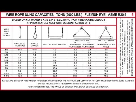
Vertical, or straight, attachment is simply using a sling to connect a lifting hook to a load. Full rated lifting capacity of the sling may be utilized, but must not be exceeded. A tagline should be used to prevent load rotation, which may damage a sling.
Choker hitches reduce lifting capability of a sling since this method of rigging affects ability of the wire rope components to adjust during the lift. A choker is used when the load will not be seriously damaged by the sling body — or the sling damaged by the load — and when the lift requires the sling to snug up against the load.
The diameter of the bend where the sling contacts the load should keep the point of choke against the sling BODY — never against a splice or the base of the eye. When a choke is used at an angle of less than 120 degrees (see next page), the sling-rated capacity must be adjusted downward.
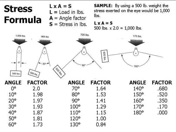
Anytime pull is exerted at an angle on a leg—or legs—of a sling, the load per leg can be determined by using the data in the table above. Proceed as follows to calculate this load—and determine the rated capacity required of the sling, or slings, needed for a lift:First, divide the total load to be lifted by the number of legs to be used. This provides the load per leg if the lift were being made with all legs being vertically.
Then multiply the load per leg (as computed above) by the Load Factor for the leg angle being used (from the table at the bottom) – to compute the ACTUAL LOAD on each leg for this lift and angle. The actual load must not exceed the rated sling capacity.
The horizontal angle of bridles with 3 or more legs is measured the same as the horizontal sling angle of 2-legged hitches. In this case, where a bridle designed with different leg lengths results in horizontal angles, the leg with the smallest horizontal angle will carry the greatest load. Therefore, the smallest horizontal angle is used in calculating actual leg load and evaluating the rated capacity of the sling proposed.
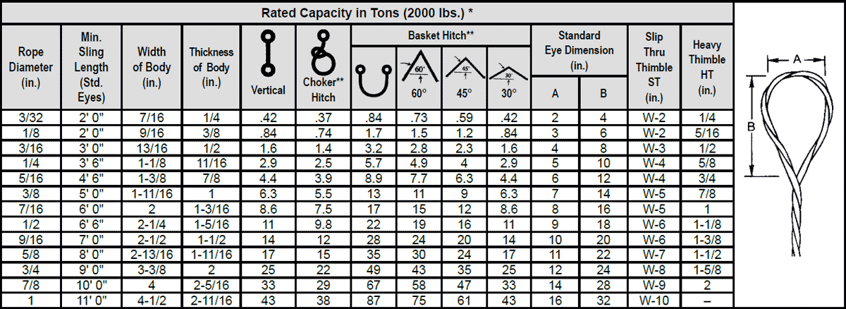
On the other hand, the eye should always be used on a hook or pin with at least the nominal diameter of the rope—since applying the D/d Ratio shows an efficiency loss of approximately 50% when the relationship is less than 1/1.
When rigged as a basket, diameterof the bend where a sling contacts the load can be a limiting factor on sling capacity. Standard D/d ratios—where “D” is the diameter of bend, and “d” the diameter of the rope—are applied to determine efficiency of various sling constructions, as indicated below:Mechanically Spliced, Single-Part Slings: 25 times rope diameter
Whether to use a single-part sling (one made of a single wire rope in the sling body) or a multi-part sling (several ropes in the body) is usually the first decision to make after determining the sling length and capacity for a lift.
The starting point for this decision involves the handling characteristics of the sling more than any other factor. Based on capacity alone, multi-part slings will be more flexible and more easily handled than single-part slings. The larger the capacity of a sling, the more important this becomes. Eventually, it becomes unrealistic to build big capacity slings from single, very large wire ropes.
In the design of the sling, rope engineers must seek a balance between strength-handling characteristics and number of parts, since there is a tendency to lose strength as core parts are added to increase flexibility.
If a load is hanging free, the normal choke angle is approximately 135 degrees. When the angle is less than 135 degrees, an adjustment in the sling-rated capacity must be made. Choker hitches at angles greater than 135 degrees are not recommended since they are unstable.

When a wire rope is bent around any sheave or other object there is a loss of strength due to this bending action. As the D/d ratio becomes smaller this loss of strength becomes greater and the rope becomes less efficient. This curve relates the efficiency of a rope diameter to different D/d ratios. This curve is based on static loads and applies to 6-strand class 6×19 and 6×37 wire rope.
When a sling is used in a BASKET- or CHOKER HITCH with D/d ratios smaller than listed in the capacity tables, the rated capacities (or WLLs) must be decreased.
For example: The BASKET and CHOKER hitch capacities listed (in all Standards and Regulations) for 6-strand ropes are based on a minimum D/d ratio of 25:1.
An object you place into a 1" diameter 6-strand wire rope sling using a basket- or choker hitch must have a minimum diameter of 25". If the object is smaller than the listed 25:1 D/d ratio the capacity (or WLL) must be decreased. Table A) illustrates the percentage of decrease to be expected.
If the object lifted with a 6-strand wire rope sling in a basket hitch is at least 25 x larger than the sling diameter (D/d 25:1) the basket capacity need not to be adjusted.
It is better to use a larger shackle or a Wide Body shackle type. If the shackle or object has at least 5x the sling diameter (D/d 5:1) the basket sling capacity must still be reduced by about 25%.
Load Hooks must have sufficient thickness to ensure proper sling D/d ratio, particularly when using slings in an inverted basket hitch; that is the sling BODY is placed into the hook and the sling EYES are facing downwards.
Endless (or Grommet) slings DO NOT HAVE A LOOP which has double the strength of the sling body. Prior to EVERY lift, YOU, the user, has to determine if the D/d ratio is equal or higher than the ones listed in the capacity tables.
There will always be a loss of sling capacity whenever a sling bends around another object. The D/d Ratio aids in determining the sling’s capacity reduction, allowing you to make corrections before continuing a lift.
Specific to polyester round slings, it varies among manufacturers, but usually, they recommend minimum hardware diameters to protect the inner core yarns. The illustration above provides an example of minimum shackle size requirements when using round slings. Bear in mind that round slings are more negatively affected by users bunching up the sling and not allowing the yarns to spread out properly and disperse the load when in a choker configuration.
Using choker hitches may save headroom; however, even following manufacturer-specified hardware diameter, the sling’s rated capacity reduces to 75% of the listed vertical rating. Failing to understand this relationship often results in overloading the sling.
While all slings lose capacity when they are bent beyond a certain point, basket hitch ratings are based on a minimum diameter and the capacity must be reduced when the sling’s D/d falls below the minimum D/d ratio. Keep in mind, a true basket is one in which the legs of the sling remain at a 90-degree vertical angle.
In the rental business, we often see rigging equipment damaged due to sling capacity reduction being ignored or miscalculated. Often, the equipment is damaged beyond repair, leading to unsafe rigging practices and additional repair or replacement costs for our customers. This is why it’s imperative to understand and abide by D/d Ratio specifications.
Enter the diameter of the wire rope, in mm, into the calculator to determine the safe working load (SWL). This calculator is for education purposes only, follow manufacturing guidelines for true SWL values.
A safe working load of a wire rope is a measure of the total load or weight that a wire rope can safely support during operation. Values greater than the SWL could result in a failure of the rope.
There is almost an endless number of wire rope applications that all have different strength and flexibility requirements. In order to determine your unique wire rope requirements, it is important to understand the basic configurations and characteristics of wire rope cable that determine its overall strength. Three primary areas that determine the strength of wire rope cable include:
As shown below, there are 3 basic parts to wire rope: the wire, the strand and the core all combine to form the wire rope. There is a standard naming convention of wire rope, which is the main component that will determine the strength of wire rope:
There is an inverse relationship between the strength of the wire rope and the flexibility / stretch of the rope as more strands and more wires per strand are added. As shown below, 1 X 19 is the least flexible but has a high breaking strength. 7 X 7 is more flexible and has medium strength and 7 X 19 is the most flexible but has the lowest breaking strength.
There are numerous configurations of miniature wire cables that we can supply based on your unique requirements. Below are some of the most common wire strand configurations:
The diameter of each individual wire, in conjunction with the wire configuration will determine the overall wire rope cable diameter. As the diameter increases, the breaking strength of the wire will also increase. It is recommended to select a cable with a minimum breaking strength of 10 times the actual load requirement that you need for your project.
There is a large assortment of materials that are used to make wire rope that will all determine the overall strength of the wire. Some of the materials we offer include Stainless Steel, Galvanized Steel, Tungsten, Nitinol, Vitallium, Inconel, Titanium, and Molybdenum. Each material not only has different purposes and applications but will also determine the overall strength of the rope.
Additionally, wire rope can be either coated or uncoated. We have a variety of coatings that also provide different flexibility and strength. We offer nylon, vinyl, FEP, polypropylene and polyethylene extruded coatings.
There are many considerations that go into determining the overall strength of wire rope and your project has a unique set of requirements. We look forward to working with you to determine exactly what type of wire rope fits your needs.


 8613371530291