
wire rope capacity formula made in china

But, when you need to calculate the accurate length of the cable or wire, or accurately calculate spool size, how should we do then? Here I will introduce a more accurate calculation method, which will help you out.
Now, let"s get into the main topic. We were thinking that the wire and cable arrange uniformly and compactly, one by one, and layer by layer, as shown in Figure 1, in the usual calculation. While, here is the question. The cable and wire will not arrange as Figure 1 , however, more likely as Figure 2. According to Figure 2, we will deduced the accurate formula.
In fact, the cable and wire do not arrange uniformly and compactly, one by one, each layer in the cable spool. There is some clearance between two windings. We assume a constant k.
The rope guide is lightweight and durable and it installs quickly and easily, with no special tools required. It is exceptionally rigid and able to withstand extreme applications and environments.
The roller wheels provide smooth transition movement, which can extend service life by reducing the wear of the rope drum and the guide itself. The guide can be made to suit a wide range of drum size and any drum pitch direction and its modular design allows for installation of devices for new features, such as drum cleaning, side-pull prevention and rope measuring.
Wire rope and cable are each considered a “machine”. The configuration and method of manufacture combined with the proper selection of material when designed for a specific purpose enables a wire rope or cable to transmit forces, motion and energy in some predetermined manner and to some desired end.
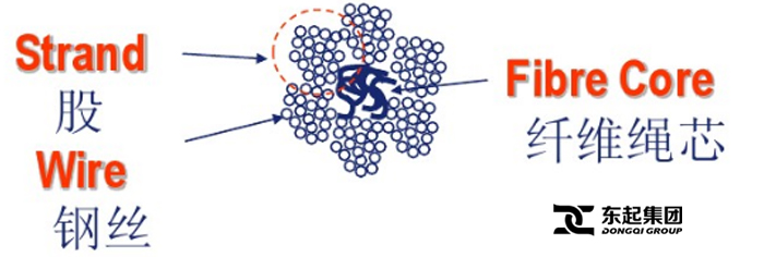
Two or more wires concentrically laid around a center wire is called a strand. It may consist of one or more layers. Typically, the number of wires in a strand is 7, 19 or 37. A group of strands laid around a core would be called a cable or wire rope. In terms of product designation, 7 strands with 19 wires in each strand would be a 7×19 cable: 7 strands with 7 wires in each strand would be a 7×7 cable.
Materials Different applications for wire rope present varying demands for strength, abrasion and corrosion resistance. In order to meet these requirements, wire rope is produced in a number of different materials.
Stainless Steel This is used where corrosion is a prime factor and the cost increase warrants its use. The 18% chromium, 8% nickel alloy known as type 302 is the most common grade accepted due to both corrosion resistance and high strength. Other types frequently used in wire rope are 304, 305, 316 and 321, each having its specific advantage over the other. Type 305 is used where non-magnetic properties are required, however, there is a slight loss of strength.
Galvanized Carbon Steel This is used where strength is a prime factor and corrosion resistance is not great enough to require the use of stainless steel. The lower cost is usually a consideration in the selection of galvanized carbon steel. Wires used in these wire ropes are individually coated with a layer of zinc which offers a good measure of protection from corrosive elements.
Cable Construction The greater the number of wires in a strand or cable of a given diameter, the more flexibility it has. A 1×7 or a 1×19 strand, having 7 and 19 wires respectively, is used principally as a fixed member, as a straight linkage, or where flexing is minimal.
Selecting Wire Rope When selecting a wire rope to give the best service, there are four requirements which should be given consideration. A proper choice is made by correctly estimating the relative importance of these requirements and selecting a rope which has the qualities best suited to withstand the effects of continued use. The rope should possess:Strength sufficient to take care of the maximum load that may be applied, with a proper safety factor.
Strength Wire rope in service is subjected to several kinds of stresses. The stresses most frequently encountered are direct tension, stress due to acceleration, stress due to sudden or shock loads, stress due to bending, and stress resulting from several forces acting at one time. For the most part, these stresses can be converted into terms of simple tension, and a rope of approximately the correct strength can be chosen. As the strength of a wire rope is determined by its, size, grade and construction, these three factors should be considered.
Safety Factors The safety factor is the ratio of the strength of the rope to the working load. A wire rope with a strength of 10,000 pounds and a total working load of 2,000 pounds would be operating with a safety factor of five.
It is not possible to set safety factors for the various types of wire rope using equipment, as this factor can vary with conditions on individual units of equipment.
The proper safety factor depends not only on the loads applied, but also on the speed of operation, shock load applied, the type of fittings used for securing the rope ends, the acceleration and deceleration, the length of rope, the number, size and location of sheaves and drums, the factors causing abrasion and corrosion and the facilities for inspection.
Fatigue Fatigue failure of the wires in a wire rope is the result of the propagation of small cracks under repeated applications of bending loads. It occurs when ropes operate over comparatively small sheaves or drums. The repeated bending of the individual wires, as the rope bends when passing over the sheaves or drums, and the straightening of the individual wires, as the rope leaves the sheaves or drums, causing fatigue. The effect of fatigue on wires is illustrated by bending a wire repeatedly back and forth until it breaks.
The best means of preventing early fatigue of wire ropes is to use sheaves and drums of adequate size. To increase the resistance to fatigue, a rope of more flexible construction should be used, as increased flexibility is secured through the use of smaller wires.
Abrasive Wear The ability of a wire rope to withstand abrasion is determined by the size, the carbon and manganese content, the heat treatment of the outer wires and the construction of the rope. The larger outer wires of the less flexible constructions are better able to withstand abrasion than the finer outer wires of the more flexible ropes. The higher carbon and manganese content and the heat treatment used in producing wire for the stronger ropes, make the higher grade ropes better able to withstand abrasive wear than the lower grade ropes.
Effects of Bending All wire ropes, except stationary ropes used as guys or supports, are subjected to bending around sheaves or drums. The service obtained from wire ropes is, to a large extent, dependent upon the proper choice and location of the sheaves and drums about which it operates.
A wire rope may be considered a machine in which the individual elements (wires and strands) slide upon each other when the rope is bent. Therefore, as a prerequisite to the satisfactory operation of wire rope over sheaves and drums, the rope must be properly lubricated.
Loss of strength due to bending is caused by the inability of the individual strands and wires to adjust themselves to their changed position when the rope is bent. Tests made by the National Institute of Standards and Technology show that the rope strength decreases in a marked degree as the sheave diameter grows smaller with respect to the diameter of the rope. The loss of strength due to bending wire ropes over the sheaves found in common use will not exceed 6% and will usually be about 4%.
The bending of a wire rope is accompanied by readjustment in the positions of the strands and wires and results in actual bending of the wires. Repetitive flexing of the wires develops bending loads which, even though well within the elastic limit of the wires, set up points of stress concentration.
The fatigue effect of bending appears in the form of small cracks in the wires at these over-stressed foci. These cracks propagate under repeated stress cycles, until the remaining sound metal is inadequate to withstand the bending load. This results in broken wires showing no apparent contraction of cross section.
Experience has established the fact that from the service view-point, a very definite relationship exists between the size of the individual outer wires of a wire rope and the size of the sheave or drum about which it operates. Sheaves and drums smaller than 200 times the diameter of the outer wires will cause permanent set in a heavily loaded rope. Good practice requires the use of sheaves and drums with diameters 800 times the diameter of the outer wires in the rope for heavily loaded fast-moving ropes.
It is impossible to give a definite minimum size of sheave or drum about which a wire rope will operate with satisfactory results, because of the other factors affecting the useful life of the rope. If the loads are light or the speed slow, smaller sheaves and drums can be used without causing early fatigue of the wires than if the loads are heavy or the speed is fast. Reverse bends, where a rope is bent in one direction and then in the opposite direction, cause excessive fatigue and should be avoided whenever possible. When a reverse bend is necessary larger sheaves are required than would be the case if the rope were bent in one direction only.
Stretch of Wire Rope The stretch of a wire rope under load is the result of two components: the structural stretch and the elastic stretch. Structural stretch of
CIVMATS produces high quality stainless steel wire rope. Our annual production capacity is roughly 8000 tons, among which stainless steel wire rope amounts to 400 tons per month. The tolerance of our stainless steel wire rope can be as small as ±0.01mm. CIVMATS produces strictly according to ISO9001:2000. Every product delivered from CIVMATS is a reputation warranty.
Wire rope can be divided into multi-strand wire rope and single-strand wire rope. It is structured with at least two layers of steel wire or a plurality of strands spirally wound around a center or a core. Stainless steel wire rope refers to a steel wire rope made of stainless steel. In dynamic systems, stainless steel wire ropes are widely applied in the lifting of cranes and elevators, the transmission of mechanical power, the control of automobile cockpit poles and the operation of aircraft control systems, etc. In static systems, stainless steel wire ropes are also employed in various industries such as the stability of the sling bridge"s pulling support tower and the design of new railings.
Stainless steel wire rope features high temperature resistance, good fatigue resistance, excellent breaking force, long service life and durability. It is widely used in coal, petroleum, metallurgy, chemical industry, shipbuilding, bridge, electric power, rubber, military, tourism, water conservancy and light industry. The products can be produced according to ISO, BS, DIN, JIS, ABS, LR and other international and foreign advanced standards
In CIVMATS, all of our stainless steel wire ropes are packaged as per international standard to prevent any possible damage or loss. They are neatly wrapped in accurate length with securely tied rope ends. For enhanced customer experience, we also provide dedicated package as per your special requirements.
Our main grades for stainless steel wire rope are 304 and 316. We can also customize stainless steel wire rope as per your specified grades and sizes for your reference.
1. Point contact: The adjacent stainless steel wires contact in the form of point in the strands. The diameters of all the stainless steel wires, excluding the central wire are equal, and the strands are formed by layering.
2. Line contact: There is a linear contact between the adjacent layers of stainless steel wire in the strand, and the strands are made of stainless steel wires of different diameters in one process.
4. Point and line contact: There are two kinds of contact forms between the adjacent layers of stainless steel wires in the strand. The strands are made of wires of different diameters.
1. In the equipment reform of chemical, fertilizer, chemical fiber and other industries, stainless steel wire rope was used for the deployment of the updated equipment.
2. Stainless steel wire ropes are used in the applications of popular stainless steel welding rods and a considerable number of stainless steel components, springs, connecting parts, etc.,
5. Stainless steel wire ropes are also extensively used in railway electrification, decoration industry, rigging industry, fishing gear industry, automobile and motorcycle industry and other industries.
Original equipment wire rope and replacement wire rope must be selected and installed in accordance with the requirements of this section. Selection of replacement wire rope must be in accordance with the recommendations of the wire rope manufacturer, the equipment manufacturer, or a qualified person.
Wire rope design criteria: Wire rope (other than rotation resistant rope) must comply with either Option (1) or Option (2) of this section, as follows:
Option (1). Wire rope must comply with section 5-1.7.1 of ASME B30.5-2004 (incorporated by reference, see § 1926.6) except that section"s paragraph (c) must not apply.
Option (2). Wire rope must be designed to have, in relation to the equipment"s rated capacity, a sufficient minimum breaking force and design factor so that compliance with the applicable inspection provisions in § 1926.1413 will be an effective means of preventing sudden rope failure.
Type I rotation resistant wire rope ("Type I"). Type I rotation resistant rope is stranded rope constructed to have little or no tendency to rotate or, if guided, transmits little or no torque. It has at least 15 outer strands and comprises an assembly of at least three layers of strands laid helically over a center in two operations. The direction of lay of the outer strands is opposite to that of the underlying layer.
Type II rotation resistant wire rope ("Type II"). Type II rotation resistant rope is stranded rope constructed to have significant resistance to rotation. It has at least 10 outer strands and comprises an assembly of two or more layers of strands laid helically over a center in two or three operations. The direction of lay of the outer strands is opposite to that of the underlying layer.
Type III rotation resistant wire rope ("Type III"). Type III rotation resistant rope is stranded rope constructed to have limited resistance to rotation. It has no more than nine outer strands, and comprises an assembly of two layers of strands laid helically over a center in two operations. The direction of lay of the outer strands is opposite to that of the underlying layer.
Type I must have an operating design factor of no less than 5, except where the wire rope manufacturer and the equipment manufacturer approves the design factor, in writing.
A qualified person must inspect the rope in accordance with § 1926.1413(a). The rope must be used only if the qualified person determines that there are no deficiencies constituting a hazard. In making this determination, more than one broken wire in any one rope lay must be considered a hazard.
Each lift made under § 1926.1414(e)(3) must be recorded in the monthly and annual inspection documents. Such prior uses must be considered by the qualified person in determining whether to use the rope again.
Rotation resistant ropes may be used as boom hoist reeving when load hoists are used as boom hoists for attachments such as luffing attachments or boom and mast attachment systems. Under these conditions, all of the following requirements must be met:
The requirements in ASME B30.5-2004 sections 5-1.3.2(a), (a)(2) through (a)(4), (b) and (d) (incorporated by reference, see § 1926.6) except that the minimum pitch diameter for sheaves used in multiple rope reeving is 18 times the nominal diameter of the rope used (instead of the value of 16 specified in section 5-1.3.2(d)).
The operating design factor for these ropes must be the total minimum breaking force of all parts of rope in the system divided by the load imposed on the rope system when supporting the static weights of the structure and the load within the equipment"s rated capacity.
Wire rope clips used in conjunction with wedge sockets must be attached to the unloaded dead end of the rope only, except that the use of devices specifically designed for dead-ending rope in a wedge socket is permitted.
Prior to cutting a wire rope, seizings must be placed on each side of the point to be cut. The length and number of seizings must be in accordance with the wire rope manufacturer"s instructions.
Wire rope and cable are each considered a “machine”. The configuration and method of manufacture combined with the proper selection of material when designed for a specific purpose enables a wire rope or cable to transmit forces, motion and energy in some predetermined manner and to some desired end.
Two or more wires concentrically laid around a center wire is called a strand. It may consist of one or more layers. Typically, the number of wires in a strand is 7, 19 or 37. A group of strands laid around a core would be called a cable or wire rope. In terms of product designation, 7 strands with 19 wires in each strand would be a 7×19 cable: 7 strands with 7 wires in each strand would be a 7×7 cable.
Materials Different applications for wire rope present varying demands for strength, abrasion and corrosion resistance. In order to meet these requirements, wire rope is produced in a number of different materials.
Stainless Steel This is used where corrosion is a prime factor and the cost increase warrants its use. The 18% chromium, 8% nickel alloy known as type 302 is the most common grade accepted due to both corrosion resistance and high strength. Other types frequently used in wire rope are 304, 305, 316 and 321, each having its specific advantage over the other. Type 305 is used where non-magnetic properties are required, however, there is a slight loss of strength.
Galvanized Carbon Steel This is used where strength is a prime factor and corrosion resistance is not great enough to require the use of stainless steel. The lower cost is usually a consideration in the selection of galvanized carbon steel. Wires used in these wire ropes are individually coated with a layer of zinc which offers a good measure of protection from corrosive elements.
Cable Construction The greater the number of wires in a strand or cable of a given diameter, the more flexibility it has. A 1×7 or a 1×19 strand, having 7 and 19 wires respectively, is used principally as a fixed member, as a straight linkage, or where flexing is minimal.
Selecting Wire Rope When selecting a wire rope to give the best service, there are four requirements which should be given consideration. A proper choice is made by correctly estimating the relative importance of these requirements and selecting a rope which has the qualities best suited to withstand the effects of continued use. The rope should possess:Strength sufficient to take care of the maximum load that may be applied, with a proper safety factor.
Strength Wire rope in service is subjected to several kinds of stresses. The stresses most frequently encountered are direct tension, stress due to acceleration, stress due to sudden or shock loads, stress due to bending, and stress resulting from several forces acting at one time. For the most part, these stresses can be converted into terms of simple tension, and a rope of approximately the correct strength can be chosen. As the strength of a wire rope is determined by its, size, grade and construction, these three factors should be considered.
Safety Factors The safety factor is the ratio of the strength of the rope to the working load. A wire rope with a strength of 10,000 pounds and a total working load of 2,000 pounds would be operating with a safety factor of five.
It is not possible to set safety factors for the various types of wire rope using equipment, as this factor can vary with conditions on individual units of equipment.
The proper safety factor depends not only on the loads applied, but also on the speed of operation, shock load applied, the type of fittings used for securing the rope ends, the acceleration and deceleration, the length of rope, the number, size and location of sheaves and drums, the factors causing abrasion and corrosion and the facilities for inspection.
Fatigue Fatigue failure of the wires in a wire rope is the result of the propagation of small cracks under repeated applications of bending loads. It occurs when ropes operate over comparatively small sheaves or drums. The repeated bending of the individual wires, as the rope bends when passing over the sheaves or drums, and the straightening of the individual wires, as the rope leaves the sheaves or drums, causing fatigue. The effect of fatigue on wires is illustrated by bending a wire repeatedly back and forth until it breaks.
The best means of preventing early fatigue of wire ropes is to use sheaves and drums of adequate size. To increase the resistance to fatigue, a rope of more flexible construction should be used, as increased flexibility is secured through the use of smaller wires.
Abrasive Wear The ability of a wire rope to withstand abrasion is determined by the size, the carbon and manganese content, the heat treatment of the outer wires and the construction of the rope. The larger outer wires of the less flexible constructions are better able to withstand abrasion than the finer outer wires of the more flexible ropes. The higher carbon and manganese content and the heat treatment used in producing wire for the stronger ropes, make the higher grade ropes better able to withstand abrasive wear than the lower grade ropes.
Effects of Bending All wire ropes, except stationary ropes used as guys or supports, are subjected to bending around sheaves or drums. The service obtained from wire ropes is, to a large extent, dependent upon the proper choice and location of the sheaves and drums about which it operates.
A wire rope may be considered a machine in which the individual elements (wires and strands) slide upon each other when the rope is bent. Therefore, as a prerequisite to the satisfactory operation of wire rope over sheaves and drums, the rope must be properly lubricated.
Loss of strength due to bending is caused by the inability of the individual strands and wires to adjust themselves to their changed position when the rope is bent. Tests made by the National Institute of Standards and Technology show that the rope strength decreases in a marked degree as the sheave diameter grows smaller with respect to the diameter of the rope. The loss of strength due to bending wire ropes over the sheaves found in common use will not exceed 6% and will usually be about 4%.
The bending of a wire rope is accompanied by readjustment in the positions of the strands and wires and results in actual bending of the wires. Repetitive flexing of the wires develops bending loads which, even though well within the elastic limit of the wires, set up points of stress concentration.
The fatigue effect of bending appears in the form of small cracks in the wires at these over-stressed foci. These cracks propagate under repeated stress cycles, until the remaining sound metal is inadequate to withstand the bending load. This results in broken wires showing no apparent contraction of cross section.
Experience has established the fact that from the service view-point, a very definite relationship exists between the size of the individual outer wires of a wire rope and the size of the sheave or drum about which it operates. Sheaves and drums smaller than 200 times the diameter of the outer wires will cause permanent set in a heavily loaded rope. Good practice requires the use of sheaves and drums with diameters 800 times the diameter of the outer wires in the rope for heavily loaded fast-moving ropes.
It is impossible to give a definite minimum size of sheave or drum about which a wire rope will operate with satisfactory results, because of the other factors affecting the useful life of the rope. If the loads are light or the speed slow, smaller sheaves and drums can be used without causing early fatigue of the wires than if the loads are heavy or the speed is fast. Reverse bends, where a rope is bent in one direction and then in the opposite direction, cause excessive fatigue and should be avoided whenever possible. When a reverse bend is necessary larger sheaves are required than would be the case if the rope were bent in one direction only.
Stretch of Wire Rope The stretch of a wire rope under load is the result of two components: the structural stretch and the elastic stretch. Structural stretch of wire rope is caused by the lengthening of the rope lay, compression of the core and adjustment of the wires and strands to the load placed upon the wire rope. The elastic stretch is caused by elongation of the wires.
The structural stretch varies with the size of core, the lengths of lays and the construction of the rope. This stretch also varies with the loads imposed and the amount of bending to which the rope is subjected. For estimating this stretch the value of one-half percent, or .005 times the length of the rope under load, gives an approximate figure. If loads are light, one-quarter percent or .0025 times the rope length may be used. With heavy loads, this stretch may approach one percent, or .01 times the rope length.
The elastic stretch of a wire rope is directly proportional to the load and the length of rope under load, and inversely proportional to the metallic area and modulus of elasticity. This applies only to loads that do not exceed the elastic limit of a wire rope. The elastic limit of stainless steel wire rope is approximately 60% of its breaking strength and for galvanized ropes it is approximately 50%.
Preformed Wire Ropes Preformed ropes differ from the standard, or non-preformed ropes, in that the individual wires in the strands and the strands in the rope are preformed, or pre-shaped to their proper shape before they are assembled in the finished rope.
This, in turn, results in preformed wire ropes having the following characteristics:They can be cut without the seizings necessary to retain the rope structure of non-preformed ropes.
They are substantially free from liveliness and twisting tendencies. This makes installation and handling easier, and lessens the likelihood of damage to the rope from kinking or fouling. Preforming permits the more general use of Lang lay and wire core constructions.
Removal of internal stresses increase resistance to fatigue from bending. This results in increased service where ability to withstand bending is the important requirement. It also permits the use of ropes with larger outer wires, when increased wear resistance is desired.
Outer wires will wear thinner before breaking, and broken wire ends will not protrude from the rope to injure worker’s hands, to nick and distort adjacent wires, or to wear sheaves and drums. Because of the fact that broken wire ends do not porcupine, they are not as noticeable as they are in non-preformed ropes. This necessitates the use of greater care when inspecting worn preformed ropes, to determine their true condition.
Wire ropes are widely employed components in diverse areas, such as in industrial production, tourist cable cars, mining, metallurgy, shipbuilding, and elevators. Wire rope is a heavily loaded component, and long-term continuous operation eventually result in corrosion, wear, broken wires, loose wires, and fatigue, which decrease the loading strength of the rope, and can cause accidents, resulting in property damage and injury [1]. The traditional damage detection method is artificial visual inspection, which is a low efficiency, time-consuming, and unreliable method [1]. The development of a fast, non-destructive, and automatic detection technology is therefore necessary.
Wire rope defects include three main types: the loss of metallic area (LMA), local faults (FLs), and structural faults (SFs). The main non-destructive testing (NDT) methods employed for wire rope inspection include electromagnetic detection, ultrasonic guided wave (UGW) evaluation, radiation testing, eddy current inspection, and optical detection [1]. However, designing a precise detection device that can quantitatively determine the characteristics of defects, such as the number of broken wires, remains problematic, particularly when operating in severe environments [2].
The UGW method has been shown to provide a detection speed that is faster than other methods, but the method demonstrates a low anti-interference ability and suffers from strong background noise [3,4,5,6,7]. Treyssède and Laguerre’s [3] applied the transmission characteristics of UGW for wire rope testing. The researchers developed a semi-analytical finite element method, and calculated the optimal excitation and receiving sites. This approach provided a wave dispersion curve for spiral steel rope. Vanniamparambil [4] proposed a novel detection method that combined three technologies: UGW, acoustic emission techniques, and digital image processing. Xu [7] evaluated the detection precision of the UGW method for wire rope defects obtained at different frequencies, showing that wire ropes at higher frequencies had longer recovery lengths for their elastic waves. Raisuitis [5] investigated the propagation of UGWs along composite multi-wire ropes with various types of acoustic contacts between neighboring wires and the plastic core. Tse and Rostami [6] investigated the efficiency of employing the magnetostriction of ferromagnetic materials in conjunction with the UGW method for wire rope defect inspection, and the location and severity of defects were approximately identified and characterized using the short-time Fourier transform and wavelet analysis. Other detection methods, such as radiation testing [8] and eddy current inspection [9], have not been applied to wire rope inspection to a large extent.
Electromagnetic detection methods are commonly employed for the NDT of wire rope [2]. The basic principle behind wire rope electromagnetic detection is illustrated in Figure 1. The lower permeability of the air leads to magnetic field leakage (MFL) from the rope defect, and the strength of the MFL can be obtained from an appropriately designed magnetic detection device. In terms of the type of excitation source employed, electromagnetic detection can be divided according to the use of a coil [10,11] or a permanent magnet [12,13,14,15,16,17] for generating a magnetic field. Modified main-flux equipment has been developed for wire rope inspection, which induced changes in the electromagnetic field strength owing to the leakage field derived from defects in various large-diameter wire ropes [10]. Other researchers [11] employed a pair of saddle coils for the magnetization of a steel track rope, and this system was applied to detect small, inner flaws in the rope. Permanent magnets have been employed in a saddle structure to saturate wire rope in a uniform magnetic field [14,15,16,17]. Wang et al. [12] investigated the effect of excitation distance and the lift-off distance between the sensors and the wire rope surface on the detection precision. The researchers accordingly modified the magnetic circuit of the detector to restrain the impact of fluctuations in the sensor lift-off distance. Xu et al. [18] developed a magnetic excitation model. Based on this model, the researchers established design criteria for the size of the excitation structure, proposed a theoretical framework for the excitation structure size based on numerical analysis, and adjusted the theoretical design using finite element analysis (FEA).
Obtaining a precise MFL signal is the most important aspect for the accurate electromagnetic NDT of wire rope. For MFL signal acquisition, a commonly employed in-service NDT method utilizes an induction coil [10,17], Hall effect sensor [14,18,19,20,21], giant magnetoresistive (GMR) sensor [11,22], and tunnel magnetoresistive (TMR) sensor [23]. Jomdecha and Prateepasen [10] modified a conventional induction coil into a coil array that densely covered the wire rope to acquire the MFL signal. Wang and Tian [14] utilized FEA to address the problems associated with the weak MFL signals derived from small defects, and they investigated the gathered magnetism of the magnetization rope. They designed a detector with an annular pole polymagnet on one side using Hall elements as inductors. This detection system was able to capture weak MFL signals within the strong magnetic field. Xu and Wang [18] developed an online modular-detector NDT system using a Hall effect sensor that successfully detected inner broken wires. The researchers also presented three filtering algorithms. Detectors based on Hall effect sensor arrays have been widely applied for NDT under strong magnetic field conditions [19,20,21]. Cao [19] created an image from the defect data which was obtained by Hall sensors array, and applied digital image processing to extract and detect defect characteristics. Zhang et al. [20] employed signal processing to suppress the effect of lift-off distance, and applied statistical processing to distinguish different types of defects and to obtain binary image data describing the spatial extent of defects. Zhang et al. [21] applied a space filter to suppress the texture of strand waves after obtaining MFL gray-level images of wire rope defects, and the image spectrum texture was extracted as the characteristic vector used for recognition. GMR sensors have been employed for MFL signal acquisition because of their high sensitivity, high precision, and small size. GMR sensors were placed into a sensor array and densely distributed on the wire rope surface in a manner similar to that employed in a Hall effect sensor application [11]. Zhang and Tan [22] utilized the high sensitivity of a GMR sensor to develop a detection technique based on remanence magnetization, which combined the benefits of a simple structure and high detection speed with high precision. Wu et al. [23] demonstrated that TMR sensors can be applied to detect small discontinuities on a wire rope surface.
MFL signals contain a variety of distinct noise signals, which makes the development of an efficient de-noising algorithm challenging work. Currently, a number of noise reduction algorithms are commonly employed, including wavelet analysis de-noising, low-pass filter, notch filter [21], adaptive filter [20], morphological filter [24], and a de-noising algorithm based on compressed sensing (CS) [22]. Zhang et al. [20] applied digital image processing to develop a space filter for smoothing the defects in an MFL signal image. Zhang et al. [21] proposed a baseline estimation algorithm to suppress the effect of undulations in the lift-off distance and an adaptive notch filtering algorithm to filter the strand wave for increasing the signal-to-noise ratio. Zhang and Tan [22] utilized wavelet multi-resolution analysis to eliminate the baseline of the signal. Their work was based on the CS wavelet de-noising algorithm, and they calculated the best sparse transform expression to completely filter out the noise. Tian et al. combined the wavelet transform and the morphological transform to create a morphological filter algorithm that suppressed the interference associated with the baseline drift in the wire rope signal. Artificial neural networks have been widely applied to realize the quantitative detection of wire rope defects. These networks operate much like back propagation (BP) neural networks employed by a number of researchers [20,21,22]. However, BP neural networks suffer from some limitations and shortcomings, such as poor generalization and slow convergence.
To overcome the disadvantages of existing detection devices, we developed a prototype device based on the RMF of a wire rope. This inspection method utilizes GMR sensors for excitation signal acquisition. After magnetizing the wire rope with permanent magnets, the GMR sensor array was utilized to obtain the RMF strength of the rope surface. This detection system is non-contact and non-invasive which prolongs the service life of test equipment. A novel filter algorithm based on the Hilbert-Huang transform (HHT) and compressed sensing wavelet filtering (CSWF) was developed to suppress the various system noises. The HHT was employed to remove the DC component of the signal and balance the sensor channels. CSWF was employed to suppress high-frequency noises and strand waves. Then, we applied digital image processing to create a binary image using a filter based on corrosion and expansion. Subsequently, defects were located and segmented within the gray-level image. Because an 18 GMR sensor array was employed, the resulting gray-level image included only 18 pixels in its circumference. Three spline interpolations were performed to improve the circumferential resolution of the gray-level image. Thirteen image characteristics comprising 6 image textures and seven invariant moments were extracted as defect feature vectors. A radial basis function (RBF) neural network, which is a fast-learning classification network that provides a global optimum, was adopted to quantitatively detect the number of broken wires in the rope. Experimental results demonstrate that, when the absolute limiting error for the detected number of broken wires is 2, the recognition rate is as high as 93.75% with an average recognition error of 0.7813 wires.

Wire rope is widely used in mining operations due to its high strength, light weight, and good elasticity [1,2]. However, the degree of damage sustained by the wire rope increases considerably with the increase in the usage time and due to the increase in the long-term impact of factors such as tensile bending, alternating loads, and the environment. Furthermore, this damage is inevitable if it is not addressed in time, and it can adversely affect the productivity of mining operations and threaten the safety of both the personnel and the equipment. Coal mine safety regulations have been established to ensure the productivity of mining operations; according to these regulations, mining hoist ropes must be tested every day and their scrap period is two years. If the degree of damage does not exceed the relevant provisions, their usage can be extended by no more than one year.
Various methods have been proposed for the non-destructive testing of wire ropes. Most of the current studies are focused on methods such as ultrasonic detection [3], electromagnetic detection [4], X-ray detection, and magnetostriction [5], as well as eddy current, current, and vibration detection [6,7]. The electromagnetic detection method is the most widely implemented method, owing to its demonstrated reliability and practicality. The basic principle of the electromagnetic-based leakage detection method used in this study is shown in Figure 1. The permanent magnet magnetizes the wire rope to saturation, forming a closed magnetic circuit among the wire rope, magnet, and yoke. In the presence of a damage, the original magnetic induction lines through the wire rope form a closed magnetic circuit in the air and generate a leakage magnetic field.
When using the electromagnetic detection method to detect leakage, the wire rope detection signal is mixed with a variety of sources of interference noise, including the spiral structure of the wire rope, which produces periodic changes in the strand noise; the detection of the magnetic field in an environment of complex and variable high-frequency low-amplitude noise; the shaking of the wire rope during the operation process, producing low -frequency random noise; electromagnetic interference issuing from the electromagnetic detection circuit; detection line voltage jitter; drift; and other sources of noise, all of which affect the accurate judgment of the leakage signal. To address the aforementioned challenges, Peng, F. et al. [8] applied a multi-stage filtering method based on EEMD and optimal wavelets in three-dimensional UME signal processing to effectively suppress noise interference. Zhang, J. et al. [9] proposed a new filtering system consisting of the Hilbert yellow transform and compressive-aware wavelet filtering to denoise strand and high-frequency noises. Furthermore, Chun et al. [10] designed a filter based on the multi-stage wavelet analysis of a time-domain-reflection method. Moreover, they effectively eliminated the wild-point noise and industrial frequency interference noise. The abovementioned wire rope damage signal has been studied extensively. However, because the effect of wavelet packet decomposition depends on the choice of the wavelet basis function and the number of decomposition layers, it is not an adaptive signal decomposition method. In recent years, EMD has been widely used in mechanical fault diagnosis. However, owing to the existence of endpoint effects and modal confusion, this algorithm needs to be further studied. To address the limitations of EMD and WT, Dragomiretskiy et al. [11] proposed a new adaptive time-frequency analysis method called VMD in 2014. Compared with EMD and AWT, VMD can suppress interference signals, prevent the loss of useful information, and provide a high-quality data source for subsequent feature extraction. Moreover, it has high decomposition accuracy and operational efficiency and can effectively suppress the overlap mode in a signal decomposition process.
Wire rope detection is challenging because of signal noise reduction, as well as the difficulties involved in achieving a quantitative detection process following noise reduction, owing to the complex structure, shape, and location of the wire rope, which itself produces different types of defects. To solve this problem, some scholars have conducted representative studies. Li, J. et al. designed a nondestructive wire rope inspection device which used double detection plates to collect MFL data, improved the image resolution based on a super-resolution algorithm, and finally used the AdaBoost classifier to classify the defect images [12]. Zhang, J. designed a device based on a residual magnetic field device, proposing a novel filtering system to improve the signal-to-noise ratio, and at the same time used digital image processing techniques to achieve the quantitative recognition of defect images [13,14]. Tan, X. proposed a novel test structure with a huge array of magnetoresistive sensors to effectively identify multiple types of damage and finally applied radial basis neural networks for the quantitative recognition of magnetic images [15]. W Sharatchandra Singh et al. designed an ultrasonic sensor to detect wire rope damage signals by means of ultrasonic detection method and conducted quantitative recognition research using a BP neural network [16]. Artificial neural networks and related algorithms have contributed significantly to the field of pattern recognition. However, their recognition performance is significantly influenced by several parameters and can easily fall into a local minima in the optimization process. However, SVMs have few adjustable parameters and stable operation [17]. Thus, with fewer training samples, higher diagnostic accuracy can be achieved. Therefore, in this study we used SVMs based on PSO for the identification of internal and external wire rope damages.
In summary, it is difficult to detect the internal damage of wire ropes using the existing flaw detection equipment. Therefore, we have designed a wire rope detection device based on leakage magnetism. The detection device is implemented using permanent magnets to magnetize the wire rope, axial, and radial magnetization sensors in order to obtain the wire rope defect information. At the same time, the mapping relationship between internal damage and external damage was analyzed using the finite element method to prepare for the experiment. The VMD-AWT noise reduction method is used to reduce the noise of the original signal and calculate the wavelet information entropy based on the reconstructed signal to construct a multidimensional feature vector. Finally, the PSO-SVM algorithm is proposed to effectively and quantitatively classify and identify the internal and external defects of the wire rope using a multi-dimensional feature vector dataset.
Wire ropes are largely used in marine environment or for rigging purposes. They receive considerable loads and thus suffer a great deal of mechanical damage throughout their service life. Moreover, research has shown that the major cause of wire rope failure is excessive deterioration and corrosion, lack of maintenance and inspection, and wrong usage resulting in early discarding, reduced safety and replacement cost increase.
Sometimes damage can be easily detected, while in other cases fractured wires may occur on the inside. Hence, wire ropes should be inspected and maintained by the right person (competent person assigned by the company), to assure they’re in perfect condition. Regular inspectionsensure high rope performance, long service lifetime , safety of personnel and equipment, and reduced operating costs.
All ropes (synthetic, high modulus and wire ropes) should be inspected before and after an operation. This guideline ensures maximum safety for both a ship’s personnel and equipment. Even though it’s difficult to determine the exact service life span of ropes, there is a way to have a more precise estimation about their efficient lifecycle. Calculating the exact time ropes have been in use (e.g mooring time, mooring conditions, weather and tidal conditions) is the answer. All in all, rope inspections should occur at least once a year.
Inspecting wire ropes in particular, comes with great responsibility. Inspection results should be recorded, and any defects noticed have to be reported and addressed properly. Some defects can be repaired, while in some cases replacing a wire rope is inevitable.
Periodical inspections ofvessel deck equipment is also crucial for maintaining the good condition of wire ropes. The condition of the drum, chocks, bitts, rollers, sheaves, cable clamps and other end fittings, affect the rope’s performance, threads and cords. Make sure to mark these parts during your overall inspection.
In order to help marine officers and staff conduct successful wire rope inspections – and keep an up-to-date record of them – we have created an inspection solution that helps in maintaining and monitoring a ship’s ropes and deck equipment.
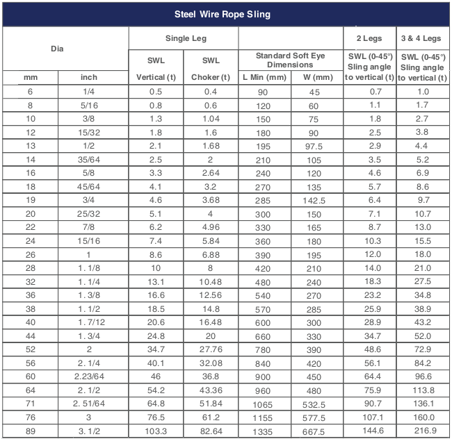
When calculating mass using F = Minimum Breaking Force, according to the wire rope’s diameter, you can determine the Minimum Breaking Massand therefore the wire’s max strength. When calculating mass using F = Safe Load according to the wire rope’s diameter, you can determine the Safe Load Mass,which is the advised load for this rope diameter.
The strands of a wire rope absorb the majority of the tensile force applied on the rope. Their design and manufacturing standards affect the level of fatigue resistance and resistance to abrasion. An easy way to understand which rope design is suitable for each purpose, is the wire rope classification.
Wire ropes are classified according to the number of strands in each construction and the number of wires in each strand. For example, a classification of 6X19 means that a wire rope of this type always has six strands, but its wires could be 15-26 per strand. This is because 19 is not the exact number of wires, but the classification of a wire number range.
Visual inspections are a common and fast way to assess wire rope condition. Both the standard and rotation resistant wire rope inspectionprocesscomply with the same four steps of examination. A ship’s crew can perform them as follows:
Steel wire rope distortion is obvious in most cases and can easily be identified by the inspector or the ship‘s crew. It usually occurs if load is suddenly applied or abruptly released (shock loading), or even if swift torque is forcefully induced.
Although not all of these deformations make the rope absolutely dangerous to use, they all may cause ropes to wear unevenly in time. This means inspections should take place more often, and distorted ropes should be handled with caution.
The rag and visual inspection is a good method for regular inspection intervals. The inspector pulls a rag along the rope trying to find broken wire cords. If the rug gets snagged by the rope, the inspector has to stop and assess the wire rope’s condition. Extreme caution should be exercised during the visual inspection, and under no circumstances should this method be the only one used to inspect wire ropes.
Tip: When you encounter a protruding wire end, bend it back and forth manually, until it separates from the wire. This will protect neighboring wires from wearing out.
Diameter reduction is a critical factor in steel wire rope wear and if not properly taken care of, it can result in rope breakage. Excessive abrasion, loss of core mass, corrosion or inner wire failure are all factors that contribute to diameter reduction.
To get an accurate measurement of the rope’s diameter, measure the rope at three different points at least 5 feet apart. Take the average of these three measurements to determine the true diameter.
Any measurements showing a reduction of ⅓ or more, indicate that a replacement should follow without delay. A diameter reduction of less than 1/3 still requires attention, and the inspector or the ship’s crew should be on guard in the next scheduled wire rope inspection.
Failure from abrasion or corrosion is a result of deficient deck equipment inspection or insufficient wire rope lubrication respectively. Internal corrosive damage is more difficult to identify than any other types of degradation. In most cases, the damage has progressed more than the external signs suggest.
Wire rope storage plays a significant role in the rope’s operation life.Wire rope corrosion and pitting can be avoided if ropes are safely stored in a clean, cool, dry and well-ventilated place. Steel wire ropes should not by any means rest on the floor, and should be protected from water, dust or any chemical fumes. Long term storage requires periodic greasing, turning the reel upside down for preventing grease dripping and possibly re-winding to another reel with larger inner tube diameter.
Wire ropes should be maintained with periodical lubrication. In order to prevent internal corrosion, a pressure lubricator is suggested to be used. In this case, a small amount of grease is used to lubricate the rope internally, while the deck stays grease-clean. Pressure lubricators clean the rope before they grease it so that the new grease enters a clean rope. The type of grease used is very important for maximum protection and greasing efficiency.
Steel wire ropes exposed to dirt, grime and other contaminants, have to be cleaned with a wire brush and petroleum (unless a pressure lubricator is used). Optimal cleaning of wire ropes can extend their service life and guarantee safe operations.
The reeling process is of high importance for the longevity of wire ropes. To protect them from being damaged, it is important that the surface of the drum is clean, smooth and dry. Improper reeling may cause wire-rope strands to spread or get flattened, when in contact with one another, as successive layers are being spooled and upper layers apply pressure on the lower ones.
Katradis S.A. offers a wide range of top quality wire ropes for shipping (mooring and hoisting operations), fishing and construction purposes. Our wire ropes have greater resistance to fatigue, and they distribute tension force equally among the rope strands. They are less likely to kink, providing higher staff safety and assuring operation success.


 8613371530291