
wire rope choker capacity free sample
Choker Hitch configurations affect the WLL of a sling. This is because the sling leg or body is passed around the load, through one end attachment or eye and is suspended by the other end attachments or eye.
In some trades it became practice to use 2 slings in a choker configuration at less than 30 degrees with the choke points facing each other. Although it makes a nice “tight” choke around pipes and bundles of steel, remember that this practice reduces your sling capacity by more than 50%!

ASCis not alone in manufacturing wire rope slings, but we make the products that assure you and your employees that all go home safely each and every day. Quality control is more than just inspection. ASC’s staff oversees every aspect and step that goes into our products not just final inspection. We begin our quality control process with the selection of the best materials, and we are only satisfied when the slings are taken out of service after serving your organization safely for many years. We take pride in our manufacturing certifications and our high work standards.
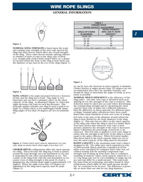
NOMINAL SLING STRENGTH is based upon the nominal (catalog) rope strength of the wire rope used in the sling and other factors which affect the overall strength of the sling. These other factors include splicing efficiency, number of parts of rope in the sling, type of hitch (e.g., straight pull, choker hitch, basket hitch, etc.), diameter around which the body of the sling is bent (D/d) and the diameter of pin used in the eye of the sling.
SLING ANGLE is the angle measured between a horizontal line and the sling leg or body. This angle is very important and can have a dramatic effect on the rated capacity of the sling. As illustrated (Figure 2),when this angle decreases, the load on each leg increases. This principle applies whether one sling is used to pull at an angle, in a basket hitch or for multi-legged bridle slings. Sling angles of less than 30 degrees are not recommended.
CHOKER HITCH configurations affect the rated capacity of a sling. This is because the sling leg or body is passed around the load, through one end attachment or eye and is suspended by the other end attachment or eye. The contact of the sling body with the end attachment or eye causes a loss of sling strength at this point. If a load is hanging free, the normal choke angle is approximately 135 degrees. When the angle is less than 135 degrees an adjustment in the sling rated capacity must be made. Extreme care should be taken to determine the angle of choke as accurately as possible.
NOMINAL SPLICE EFFICIENCY is the efficiency of the sling splice. Any time wire rope is disturbed such as in splicing an eye, the strength of the rope is reduced. This reduction must be taken into account when determining the nominal sling strength and in calculating the rated capacity. Each type of splice has a different efficiency, thus the difference in rated capacities for different types of slings. Nominal splice efficiencies have been established after many hundreds of tests over years of testing.
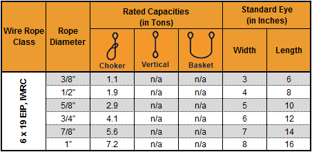
RATED CAPACITY is the maximum static load a sling is designed to lift. The tables give rated capacities in tons of 2000 pounds. Rated capacities contained in all the tables were calculated by computer. Each value was calculated starting with the nominal component rope strength and working up from there. Due to computer rounding of numeric values, rated capacity values for 2, 3 or 4 leg slings may not be even multiples of single leg values and may differ by a small amount. This represents the state-of-the-art technology and tables found in other publications which differ by this small amount should not be construed to be in error. The difference is generally no more than one unit for any sling diameter.
The Mazzella 7 x19 GAC (galvanized aircraft cable) single-leg wire rope sling has eye-and-eye endings, a mechanical splice, and galvanized zinc coating for lifting loads with vertical, choker, or basket configurations in aircraft industry applications. The 7 x 19 construction contains seven strands of wire rope with nineteen wires per strand. The wire rope construction is flexible, and has more abrasion and heat resistance than a web sling. This eye-and-eye sling has an eye, or loop, on both ends, and can be used with vertical, choker, and basket lifting configurations. The eyes are secured with a mechanical (also called Flemish) splice, which is stronger than a hand splice. The galvanized (zinc) coating has greater corrosion resistance than a bright (uncoated) wire rope. This sling has a minimum D/d ratio of 10 and meets American Society of Mechanical Engineers (ASME) specification B30.9 and Occupational Safety and Health Administration (OSHA) specification 1910.184.
Slings are used to lift heavy objects for industrial applications. Types of slings include web slings, wire rope slings, chain slings, and mesh slings. The appropriate type of sling for an application depends on the strength-to-weight ratio, flexibility and resistance to bending, resistance to abrasion and cutting, resistance to crushing, resistance to stretching, and resistance to high temperatures and other environmental stressors. Slings have one, two, three, or four legs; or a continuous loop of webbing or wire rope. Legs are support branches that extend from a single point at the top of the sling to the item being lifted so the weight of the load is distributed evenly among the branches. Slings have eyes (loops) or alloy steel fittings on the ends.
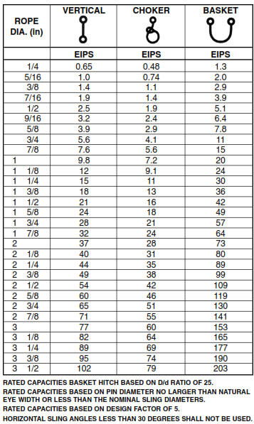
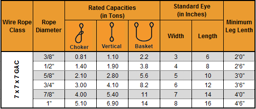
A vertical lifting configuration connects a crane hook directly to a load with a single, vertical sling, usually by means of a hook. In a choker configuration, the sling wraps entirely around the load, and one loop passes through the other to form a slip noose, or choker. In a basket configuration, the sling passes under the load and both ends of the sling connect to the crane hook. Load capacity is the maximum weight to be lifted in a vertical configuration. The capacity in a choker configuration is approximately equal to the vertical capacity times 0.8. The capacity in a basket configuration, with sling ends at a 90-degree angle, is approximately equal to twice the vertical capacity. Load capacity in a basket configuration decreases if the angle of the sling is less than 90 degrees. For example, a sling with a capacity of 2,000 lb. in a vertical configuration will have an approximate capacity of (2,000)(0.8)=1,600 lb. in a choker configuration and an approximate capacity of (2,000)(2)=4,000 lb. in a basket configuration, if the sling ends are at a 90-degree angle to the load. A wire rope sling"s capacity in a basket configuration applies only when the configuration meets the sling"s minimum D/d ratio, which is the ratio of the diameter of the rope"s curve around the load (D) to the diameter of the sling (d). If the minimum D/d ratio is not met, the capacity of the sling is decreased.
(a) Wire rope slings must be made from new or unused regular lay wire rope. The wire rope must be manufactured and tested in accordance with ASTM A 1023-02 and ASTM A 586.
(f) Wire rope clips, if used, must be installed and maintained in accordance with the recommendations of the clip manufacturer or a qualified person, or in accordance with the provisions of ASME B30.26-2010.
(g) You must not use slings made with wire rope clips as a choker hitch.Note:If using wire rope clips under these conditions, follow the guidance given in Table 5.
Number, Torque Values, and Turn Back Requirements for U-Bolt Wire Rope ClipsNumber, Torque Values, and Turn Back Requirements for Double Saddle (Fist Grip) Wire Rope Clips
•Slings made of rope with 6x19 and 6x36 classification.A minimum clear length of rope 10 times the rope diameter between splices, sleeves, or end fittings (see Figure 4, Minimum Sling Length) unless approved by a qualified person.
•Braided slings.A minimum clear length of rope 40 times the component rope diameter between the loops or end fittings (see Figure 5, Minimum Braided Sling Length) unless approved by a qualified person.
(b) You must rate slings with the load capacity of the lowest rated component of the sling. For example, if you use fittings that are rated lower than the sling material itself, identify the sling with the lower rated capacity.
(3) Identification information. All wire rope slings must have legible identification information attached to the sling which includes the information below, see sample tag in Figure 6. For slings in use that are manufactured before the effective date of this rule, the information below must be added before use or at the time the periodic inspection is completed.
Sample Wire Rope Sling ID TagNote:Sample tag for a 1/2" single-leg sling 6x19 or 6x36 classification, extra improved plow steel (EIPS) grade fiber core (FC) wire rope with a mechanical splice (ton = 2,000 lb).
(c) For single- or multiple-leg slings and endless slings, each leg must be proof loaded according to the requirements listed in Table 8 based on fabrication method. The proof load test must not exceed 50% of the component ropes" or structural strands" minimum breaking strength;
Note: For mechanical splice, swaged socket and poured socket slings follow the rope manufacturer"s recommendations for proof load testing provided that it is within the above-specified proof load range, including (c) of this subsection.
(a) You must use wire rope slings within the rated loads shown in Tables 7 through 15 in ASME B30.9-2010. For angles that are not shown in these tables, either use the rated load for the next lower angle or have a qualified person calculate the rated load.
(c) Rated loads for slings used in a choker hitch must conform to the values shown in the above referenced tables, provided that the angle of choke is 120 degrees or greater. See Figure 9 and Table 10, Angle of Choke.
(d) You must use either Figure 9 and Table 10, the manufacturer, or a qualified person to determine the rated load if the angle of choke in a choker hitch is less than 120 degrees.
(e) You must decrease the rated load of the sling when D/d ratios (Figure 8) smaller than 25 to one. Consult the sling manufacturer for specific data or refer to the Wire Rope Sling User"s Manual (wire rope technical board).
Industrial wire ropes are designed for extreme resilience and strength. They can withstand thousands of pounds of pressure and be used on all types of applications. However, issues with the wire rope installation process can significantly decrease its longevity and even its capacity and durability.
When wire ropes are not used properly, it can create an unsafe environment. The rope can snap, even if the load it’s supporting is below its maximum load limit. In anoted by the IMCA (International Marine Contractors Association), a wire rope sling rope broke due to improper installation. A crew member was seriously injured after the sling disconnected and hit the worker.
Many of these common accidents are easily avoidable through correct wire rope installation. Here are five of the most common mistakes made and how to prevent them on your worksite.
Determining the diameter of the wire rope is an essential step of the installation process. Installers are required to double-check that the correct diameter rope is being used, as this impacts the rope’s breaking strength and load limit.
Wire ropes are measured with a parallel-jawed caliper (also called a machinist’s caliper). This is placed over the wire rope to measure the diameter – but if the rope is inserted at the wrong angle, you will get an inaccurate result.
The strands of a wire rope must be flush against the measuring portion of the caliper. If a raised strand is at the top, the measurement will have a smaller dimension, which could affect breaking strength calculations.
Wire ropes are reeled onto these spools for easy handling and shipments, as it prevents the rope from getting tangled or crushed. But unreeling the wire rope incorrectly can cause severe damage, such as snagged wires, twists, kinks, or unraveled strands.
A common mistake that is often made is to unreel the wire rope by laying the spool vertically on its axis. The wire rope has to be yanked off of the spool, which increases the likelihood of it getting kinked or twisted. The wire rope should also not touch the ground as it is unreeled, as this could damage the wires as well.
Instead, the reeled wire rope should be placed on a shaft that allows the spool to turn 360°. It also should require two people, one to slowly pull the rope off of the spool in a straight line and another to regulate the speed by controlling the turn rate.
Occasionally ais added during wire rope installation to create a load-bearing eye or to connect two cables together. These small but mighty pieces only diminish a wire rope’s strength by around 10%, if they are added correctly.
These little issues can cause the wire rope to slip out of the clip. It is very important to follow the directions and use the right number of clips with the correct spacing in-between, depending on the rope’s diameter and approximate load weight.
Sometimes a damaged wire rope can be repaired through a method called seizing. First, the rope is cut at a straight angle, then a wire is tightly wound around this end to prevent the strands from unraveling.
Two methods can be used to securely seize a wire rope. First, it can be placed at a right angle between the starting and ending point of the seizing. The wire is then wrapped around this angled piece to hold it in place, and the ends are twisted together to secure it. Another option is to wrap the seizing wire around and twist the two end pieces together, creating a tourniquet type of attachment.
The type of end preparations recommended depends on several factors. This includes the diameter of the rope and the number of wires and strands. In some cases, double seizing and fuse welding is required for additional securement. Failing to follow these instructions could result in the core or strands of the wire rope to slip and unravel.
Although wire ropes are usually damaged due to improper use, they can get ruined during storage as well. Failing to follow through with routine maintenance and storage recommendations could cause the wire rope to rust, unravel, or kink. Further, keeping your wire rope on the ground, in wet areas, or directly in hot sunlight can cause it to break down faster.
the right way can improve their long-term performance and use. This includes following all instructions during wire rope installation, as well as storage and upkeep. Wire ropes should be cleaned before going into storage and may need lubricant from time to time to protect the wires from drying out.
Wire ropes are intended to be a strong, reliable piece of industrial hardware. There is no reason to compromise its durability due to simple installation mistakes. By avoiding these common mishaps, you can ensure a far safer work environment and also extend the use of your wire ropes.
Another tip is to start by purchasing top-quality hardware from a trusted wire rope supplier. Elite Sales is proud to carry a vast selection of wire rope sizes, styles, and finishes that are made to fit many applications.
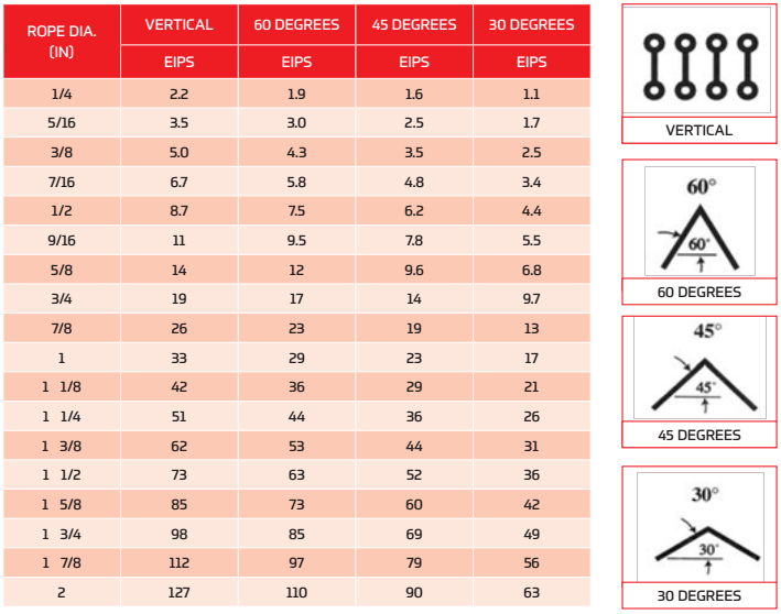
Sling Angle is the angle measured between the horizontal plane and the sling leg or body. When selecting a sling to carry a given load, it is important to consider the angle at which it is going to be used. The angle is vey important and can have a dramatic effect on the rated capacity, due to the increase of tension caused by the angle.
As an example, one sling in a basket hitch or two slings attached to one crane hook are different applications involving different sling angles. The degree of the angle will determine how much the capacity will be reduced. To determine if a particular sling will have the capacity required, take the angle between the sling leg and the horizontal, then multiply the sling’s rating by the factor provided in the accompanying table.


 8613371530291