
wire rope clip spacing formula for sale

Wire rope clips are quite small in relation to an entire wire rope setup, but this small hardware piece plays a key role in security and durability. The role of the wire rope clip is to join the end of the wire rope securely to create a loop. This may be used for overhead lifting, along with other numerous purposes, like:
There are different design styles for wire rope clips, but all clips work similarly. There is a rounded opening that fits around the wire rope. The clip is closed by two screws with bolts, causing the rounded opening to tighten around the wire rope, holding it firmly in place.
Since this hardware is used in applications that involve heavy equipment, which can be dangerous, wire rope clips need to be used correctly. Here are the things to keep in mind for a safe wire rope installation:
There are two types of wire rope clip designs: U-bolt or double saddle. It should be noted that only drop forged U-bold wire rope clips are permitted for overhead lifting, double saddle clips are not.
A U-bolt clip is made with a U-shaped bolt, along with a metal base or saddle piece that fits around the wire rope. This is held in place with two nuts that screw on the bottom of the clip.
A double saddle wire rope clip is made from two separate bolts that are held in place by bolts on either side. This different design is somewhat easier to use, as there is no top or bottom. However, they have a lower load capability, which is why they aren’t recommended for rigging.
There are also several types of metals used to make wire rope clips. As mentioned, drop forged clips are the only type that is permitted for overhead lifting. This is made from molten steel that is shaped into place with a ram hammer, making it quite durable. This type of clip is also hot galvanized for additional protection and corrosion resistance.
Wire rope clips may also be purchased in stainless steel and malleable electro-galvanized options. While stainless steel is a very strong metal, it is considered soft and may bend under heavy-duty applications – which is why it shouldn’t be used for overhead lifting. Malleable wire rope clips may even fracture under heavy loads and are best used for light-duty applications like fencing.
The way that a wire rope clip is installed is extremely important, as the placement and angle can interfere with its strength and hold. Before installing, the wire ropes should be inspected and the clips should be checked for several things, including:
Remember to inspect the wire rope before adding the clips on as well. Without proper care or handling, wires in the rope may snap or corrode. Even though the wire rope clips may be in good shape, they won’t hold well if the wire rope is damaged.
Be sure to double-check all safety factor calculations as well. When clips are used to create a sling for overhead lifting, it diminishes up to 75% of the wire rope’s original working load limit. Keep this in mind!
The next step in wire rope clip installation is placement and securement. First, you will measure out the end length of the wire rope that will need to be secured with the clips. A heavy-duty thimble may be added inside of the loop for added support.
Next, undo the clips so they are separated into two parts and fit the U-bolt around the two wire ropes. Then, tighten both of the bolts evenly until they are securely fastened, holding the ropes firmly in place.
Multiple clips should be used for added security with space measuring between 1.5 to 3 times the length of the clip apart. All wire rope clips must be facing the same direction and should be evenly spaced apart.
The majority of issues come with not following the proper requirements for wire clip installation. Failing to follow the rules for spacing, placement, or using the wrong type of clip can be quite dangerous, causing the rope to slip.
Another common issue is not torquing the bolts correctly. This includes both under-torquing and over-torquing. If the bolts are too tight, they will actually wear down the threads of the wire rope beneath. Be sure to follow the manufacturer’s directions on the clips for proper torquing techniques.
Finally, wire rope clips will need to be retightened or cycled out. No bolts will stay perfectly in place for a prolonged period of time, especially if there is a high level of friction. Clips should also be relocated and cycled out after multiple uses.
Ultimately, the quality of your wire rope clips should be a top priority, as this will impact how well the clips work and how long they last. You can purchase top-quality wire rope clips and additional hardware like thimbles, hooks, and wire ropes from Elite Sales. Contact us online to learn more or place an order today!

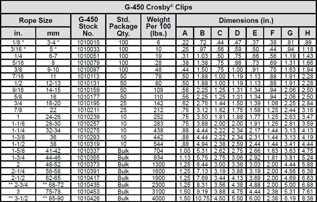
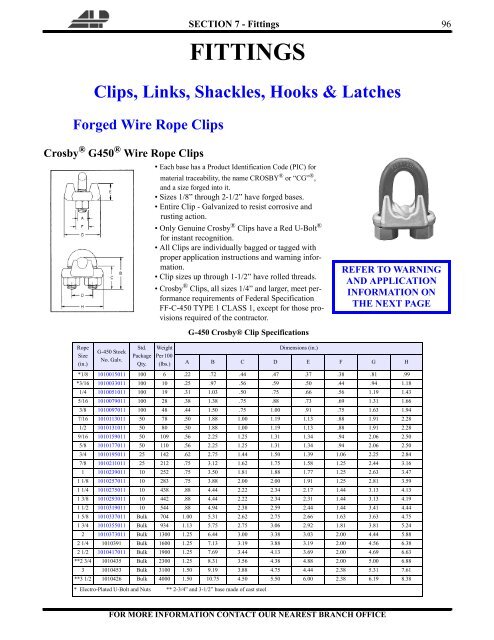
Refer to chart above in following these instructions. Turn back specified amount of rope from thimble or loop. Apply first clip one base width from dead end of rope. Tighten nuts evenly, alternating from one nut to the other until reaching the recommended torque.
When two clips are required, apply the second clip as near the loop or thimble as possible. Tighten nuts evenly, alternating until reaching the recommended torque. When more than two clips are required, apply the second clip as near the loop or thimble as possible, turn nuts on second clip firmly, but do not tighten.
When three or more clips are required, space additional clips between first two—take up rope slack—tighten nuts on all clips, alternating from one nut to the other until reaching the recommended torque.

Northern Strands, safety is one of our top priorities. Therefore, knowing how to properly clip wire rope using Crosby clips is very important in order to practice safe rigging. Keep in mind that the wire rope clip must be the correct size for the diameter of the rope that is being used and that there is a specific number of clips that are required according to rope size.
A quick rule of thumb for proper clip installation is, "Never Saddle a Dead Horse". This refers to the live end of the wire rope that rests in the saddle of the forged wire clip and the U-bolt that is placed on the dead end of the wire rope.
Employers must not use improved plow-steel wire rope and wire-rope slings with loads in excess of the rated capacities (i.e., working load limits) indicated on the sling by permanently affixed and legible identification markings prescribed by the manufacturer.
An eye splice made in any wire rope shall have not less than three full tucks. However, this requirement shall not operate to preclude the use of another form of splice or connection which can be shown to be as efficient and which is not otherwise prohibited.
Wire rope shall not be used if, in any length of eight diameters, the total number of visible broken wires exceeds 10 percent of the total number of wires, or if the rope shows other signs of excessive wear, corrosion, or defect.
Except for eye splices in the ends of wires and for endless rope slings, each wire rope used in hoisting or lowering, or in pulling loads, shall consist of one continuous piece without knot or splice.
Cable laid and 6 × 19 and 6 × 37 slings shall have a minimum clear length of wire rope 10 times the component rope diameter between splices, sleeves or end fittings.
Fiber core wire rope slings of all grades shall be permanently removed from service if they are exposed to temperatures in excess of 200 °F (93.33 °C). When nonfiber core wire rope slings of any grade are used at temperatures above 400 °F (204.44 °C) or below minus 60 °F (15.55 °C), recommendations of the sling manufacturer regarding use at that temperature shall be followed.
Wire rope slings shall have permanently affixed, legible identification markings stating size, rated capacity for the type(s) of hitch(es) used and the angle upon which it is based, and the number of legs if more than one.
If you are interested in a Wire Rope Clip, you have come to the right place. We offer U-Clips made with stainless steel or galvanized steel. These clamps are used to apply terminations on a cable assembly.
If you are looking for swage sleeves, which fulfill similar functions, we also have those available in their own category. However, if you are interested in picking up some Wire Rope Clips, we have prepared some information that you should find useful.
As we mentioned before, Wire Rope Clamps are used for a similar function to their not-so-distant cousin, the swage sleeve/ferrule. They are used to establish dead-ends and eyes at the end of a wire cable.
While using a clip may decrease the breaking strength of a rope slightly more than a swage would, there are a few advantages over swages. A Wire Rope Clip can be removed and even reused without much wear. This makes clips ideal for less permanent fixes.
When a clip is installed properly, the decrease in the breaking strength of the wire. Eyes installed with Cable Clips will maintain 80-90% of their strength. However, when a clip is not installed properly, the decrease in breaking strength will be much more significant.
Since we just discussed the importance of installing a wire clip properly, let’s talk about what you will need to get this kind of job done. If you already work with wire cables, chances are you already have everything you need.
For the most part, Galvanized Steel is a little easier on your wallet than Stainless Steel and it will take a lot of abuse without much damage to show. However Galvanized Steel is not quite as strong as Stainless Steel and it can’t be used in jobs where the rope may be exposed to saltwater or excessive moisture.
When you are choosing your wire cable, there is a general rule of thumb. Large wires generally stand up very well to abrasion but are not as resistant to fatigue as smaller wires. The size of the rope will help to determine both its strength and flexibility.
Steel Cable Clamps are used in a wide variety of applications. They can be used in towing, loading, rigging, agriculture, and household uses just to name a few areas. The key advantage to using Wire Cable Clamps is that they can be used in any application where an eye termination may need to be removed at some point.
US Rigging are a manufacturer and master distributor of climbing ropes, fall protection equipment, and industrial rigging equipment located in Santa Ana, California. This Orange County based company is proud to provide American Made products with both safety and service in mind. US Rigging has a legacy lasting over 40 years and are known for operational excellence.
We offer a variety of Wire Rope Clips to fulfill your needs in rigging, lifting, towing, and heavy construction applications. These Cable Clips are designed to reliably splice wires with dead-end eye terminations. They are perfect for applications where you need to apply terminations that can be removed.

6-1. INTRODUCTION. Section I of this chapter discusses blocks which are among the most important fittings used aboard ship on the deck, in the engine department, and in other operations. Section II covers elements of wire rope rigging which cargo handlers in a terminal service company must know. It details the care and use of wire rope, procedures for computing the safe working load and breaking strength, and inspection and handling. Section III covers marlinespike seamanship, which is a general term for handling and caring for fiber line and wire rope used aboard ship or in other marine operations.
b. Every tackle system contains a fixed block attached to some solid support and may have a traveling block attached to the load (see Figure 6-4). The single rope leaving the tackle system is called the fall line. Personnel apply the pulling force to the fall line which may be led through a leading block.
6-5. SIZES OF BLOCKS. Users can determine the size of blocks by measuring the length of the cheek in inches. Blocks are designated for use with a specific line size. Bending line over a sheave that is too small causes distortion and strain, resulting in the line wearing on the shell. Personnel can use line smaller than that designated for a sheave with no damage, but should never use line of a larger size.a. To determine the size wooden block to use with line of a known size, personnel may follow these formulas:
b. The size metal block to use with wire rope depends on the diameter of the sheave. The sheave is never less than 20 times the diameter of the wire. For example, personnel can determine the size block to use with 3/4-inch wire rope as follows:
6-8. REEVING TACKLES. Personnel reeving tackles reeve each type differently. If a tackle is rove improperly, too much friction and possible binding of the falls can result when lifting or lowering a load, creating a safety hazard. It is important to use the proper method of reeving each type of tackle up to and including a threefold purchase.
6-10. FRICTION. A certain amount of the force applied to a tackle is lost through friction. Friction occurs in a tackle when lines rub against each other or against the frame or shell of the block, and pass over the sheaves. This loss in efficiency of the block and tackle (roughly 10 percent of the load per sheave) must be added to the weight being lifted to determine the total weight. For example, to determine the total weight of a load when lifting a load of 500 pounds with a twofold purchase, personnel use the following formula and compute:TW = W x (1 + Friction) or (1 + F)
6-11. BREAKING STRESS AND SAFE WORKING LOAD. The following paragraphs explain the procedures used to determine breaking stress and safe working loads for blocks and tackle loads. The symbols used in the formula for computations are as follows:W = Weight
* This table is computed in pounds for new line. For line that has been used these figures will decrease. Old line may have only 60 percent of the strength shown in pounds for a given size of line.b. To determine the SWL for a line of known size to be rove into a tackle, personnel should use one of the following formulas as appropriate, where "C" denotes circumference and "D" denotes diameter. The formulas for manila and nylon will give the SWL in pounds. The formulas for wire rope will be in tons.
c. If personnel are unsure which type of wire rope they are using, they must always use the formula for mild steel when figuring the SWL. This will ensure ultimate safety since the different strengths of wire rope cannot be identified visually.
6-12. CARE AND USE OF WIRE ROPE. Wire rope is made of steel except for its core which is likely to be fiber. The grades of wire rope in descending order of strength are: Extra improved plow, improved plow, plow, and mild plow steel. Of these four grades, the Army uses improved plow steel extensively and plow steel to a lesser extent. The manufacturer stamps the grade on the reel. Because the grade of wire rope is not visually apparent, it should always be considered as plow steel when in doubt.
6-13. MAKEUP OF WlRE ROPE. The basic unit of wire rope is the individual wire. Wires are laid together to form strands. The number of wires in a strand varies according to the purpose for which the rope is intended. Strands are laid around a core to form the wire rope itself. With preformed plow steel wire rope, the core may be hemp or polypropylene, a synthetic fiber. The core is a foundation to keep the wire rope round, to act as a shock absorber when the wire rope contracts under strain, and to serve as a reservoir for lubricant. Figure 6-7 shows a cross section of wire rope.
b. Strand Construction. In most wire rope used today, the wires and strands are preformed. Preforming means presetting wires in the strands into a permanent corkscrew form which they will have in the completed rope. As a result, preformed wire rope does not have the internal stresses found in nonpreformed wire rope, does not untwist as readily as nonpreformed wire rope, and is more flexible.
c. Types of Lay. Lay refers to the direction of winding of the wires in the strands and the strands in the rope. Both may be wound in the same direction or in opposite directions.(1) In regular lay, the strands and wires are wound in opposite directions. Most common is the right regular lay in which the strands are wound right and the wires wound left. This lay is used in marine operations.
6-15. MEASUREMENT. Whatever its grade, wire rope is usually measured by its diameter. Figure 6-8 shows the correct method of measuring the diameter of wire rope. To measure wire rope correctly, personnel should place it in the caliper so that the outermost points of the strands will be touching the jaws of the caliper.
6-16. SAFE WORKING LOAD AND BREAKING STRENGTH. The SWL and BS formulas are listed in the paragraphs below.a. Formulas for determining the SWL of several grades of wire rope have constants that are not to be confused with safety factors. For example, the formula for the SWL in STONs (2,000 pounds) for extra improved plow steel wire rope is diameter squared multiplied by 10, or SWL = D2 x 10. The formula to find the SWL of 1-inch, 6 x 19, extra improved plow steel wire rope is as follows: SWL = D2 x 10 = 1 x 1 x 10 = STONs.
b. A figure relatively constant in marine operations, especially for new wire rope, is the SF, which is 5. The SF is used with the SWL to find the BS.
6-17. INSPECTION OF WIRE ROPES. Wire ropes should be inspected frequently and replaced if frayed, kinked, worn, or corroded. The frequency of inspection depends on how often the rope is used. Wire rope used 1 or 2 hours a week requires less frequent inspection than one used 24 hours a day.a. Common causes of wire rope failures are as follows:Using rope of incorrect size, construction, or grade.
b. Carefully inspect weak points and points of greatest stress. Worn or weak spots show up as shiny, flat spots on the wires. If the outer wires have been reduced in diameter by one-half, the wire rope is unsafe.
c. Inspect broken wires, since they show where the greatest stress occurs. If individual wires are broken next to each other, unequal load distribution at this point will make the rope unsafe. Broken wires are called fishhooks. To determine the extent of damage to the wire rope, users can slide a finger along one strand of wire for one complete turn, equal to the length of one wire rope lay. Next, count the number of fishhooks. If six or more fishhooks are discovered, the wire rope is unsafe and should be replaced immediately.
6-18. HANDLING. There are different handling methods for wire rope. These methods are listed below.a. Kinking. When loose wire rope is handled, small loops frequently form in the slack portion of the rope. If personnel apply tension to the rope while these loops are in position, the loops will not straighten out but will form sharp kinks, resulting in unlaying of the rope. Personnel should straighten these loops out of the rope before applying a load. After a kink has formed in wire rope, it is impossible to remove it, and the strength of the rope is seriously damaged at the point where the kink occurs.
b. Unreeling. When removing wire rope from a reel or coil, personnel should be sure to rotate the reel or coil. If the reel is mounted, the wire rope may be unwound by holding the end and walking away from the reel. If a wire rope is in a small coil, personnel may stand the coil on end and roll it along the deck, barge, wharf, or ground. Remove any loops that may form, although rotating the reel or coil usually avoids causing loops to form.
c. Seizing. Personnel should seize (lash together) all wire rope before cutting it. If the ends of the rope are not properly secured, the original balance of tension is disturbed. Maximum use cannot be made on wire rope when some strands carry a greater load than others.
(2) There are three formulas for determining the number and length of seizings and the space between them. When a calculation results in a fraction, the next larger whole number is used. The following formulas are based on a 3/4-inch diameter wire rope.(a) The number of seizings required equals about three times the diameter of the rope. For example: 3 x 3/4 = 2 1/4 or 3 seizings. Because the rope will be cut, six seizings are required so that there will be three on each rope end after the cut.
d. Cutting. Wire rope may be cut with a wire rope cutter, a cold chisel, a hacksaw, bolt clippers, or an oxyacetylene cutting torch. When cutting wire rope, personnel should follow the procedures outlined below.(1) To seize the wire rope, insert it into the cutter with the blade between the two central seizings, close the locking device, then close the valve on the cutter. The handle should be pumped to build up enough pressure to force the blade through the rope.
(2) Use the bolt clippers on wire rope of fairly small diameter. Use the oxyacetylene torch on wire of any diameter. Cutting with the hacksaw and cold chisel is slower than cutting with the other tools and equipment.
e. Coiling. Personnel may need to take a length of wire rope from a reel and coil it down before using it. Small loops or twists will form if the wire rope is coiled in a direction opposite to the lay. To avoid loops, users should coil right lay wire rope clockwise and left lay wire rope counterclockwise. When a loop forms in the wire, they should put a back turn in as shown in Figure 6-10.
Figure 6-10. Putting a back turn in wire ropef. Size of Sheaves and Drums. When a wire is bent over a sheave or drum, two things happen: Each wire is bent to conform to the curvature, and the wires slide against each other lengthwise because the inside arc of the rope against the sheave or drum is shorter than the outside arc. The smaller the diameter of the sheave or drum, the greater the bending and sliding. Personnel should keep this bending and moving of wires to a minimum to reduce wear. The minimum recommended sheave and drum diameter is 20 times the diameter of the rope. For example, for 5/8-inch rope: 20 x 5/8 = 12 1/2-inch sheave. If a 12 1/2-inch sheave is not on hand, personnel should use the next larger size, never a smaller size.
g. Lubrication. Wire rope is lubricated as it is manufactured. The lubricant generally does not last throughout the life of the rope, which makes relubrication necessary. Crater "C" compound is recommended, but personnel may use oil on hand rather than delay lubrication. Crater "C" compound should be heated before it is put on the wire rope. Personnel should use a brush if possible to apply lubricant. If a brush is not available, they may use a sponge or cloth, but they should look out for fishhooks or broken wires.
h. Reversing Ends. It is sometimes advisable to reverse or cut back ends to get more service from wire rope. The wear and fatigue on a rope frequently is more severe at certain points than at others. Reversing distributes stronger parts of the rope to the points getting wear and fatigue. To reverse ends, personnel remove the drum end, put it in the attachment, and then fasten the end taken from the attachment to the drum. Cutting back the ends has a similar effect, but not as much change is involved. In reversing ends, personnel should cut off short lengths of both ends to remove the sections with the greatest local fatigue.
i. Storing. Wire rope should be coiled on a spool for storage. Its grade, size, and length are noted on a tag attached to the rope or spool. Wire rope should be stored in a dry place to reduce corrosion. Personnel should not store it with chemicals or where chemicals have been stored because chemicals and their fumes can attack the metal. Personnel should always clean and lubricate wire rope before storing it.
j. Cleaning. Personnel can remove most of the dirt or grit on a used wire rope by scraping or steaming. Rust should be removed at regular intervals by wire brushing. Personnel must clean the rope carefully before lubricating to remove foreign material and old lubricant from the valleys between the strands and from the spaces between the outer wires. This permits the newly applied lubricant to freely enter the rope.
6-19. CHARACTERISTICS AND FIBER LINE. To be able to work with fiber line, personnel must know its characteristics and properties. They must be able to handle and care for the line, and tie basic knots, bends, and hitches.a. Materials for Fiber Line. Fiber line is made of either vegetable or synthetic fibers. Vegetable fibers include manila, sisal, hemp, cotton, and flax. Synthetic fibers include nylon, Dacron, polyethylene, and polypropylene. The Army primarily uses nylon synthetic fiber line, so this manual covers only that synthetic fiber.(1) Manila is a strong fiber that comes from the leaf stems of the abaca plant, a part of the banana family. Varying in length from 4 to 15 feet in their natural state, the fibers have the length and quality which gives manila rope relatively high elasticity, strength, and resistance to wear and deterioration.
(3) Hemp is a tall plant that has useful fibers for making rope and cloth. It was used extensively before manila was introduced. Now hemp"s principal use is in fittings such as ratline and marline. Because hemp is absorbent, the fittings are tarred to make them more water-resistant.
Three-strand nylon line will stretch 30 to 35 percent under an average load or a load that does not exceed the safety factor for that size line. Three-strand nylon line will stretch 40 percent without being damaged and will draw back to its original length.e. Useful Formulas. To find the SWL and BS of the various lines, some useful formulas are listed below.(1) The manufacturer states the size and BS of its lines and if available, crew members should use the manufacturer"s figures for determining the strength of line. If this information is not available, personnel should use the following formula and constant for type line to compute the SWL and the BS: C2 x constant for type line = SWL (in pounds), where "C" denotes circumference in inches. Constants for type line are as follows:
6-23. WHIPPING LINE. Personnel must never cut a line or leave the end of a line dangling loose without a whipping to prevent it from unlaying. A line without whipping will unlay of its own accord. Whenever a line or hawser has to be cut, whippings should be put on first, on each side of the cut. To prevent fraying, a temporary or plain whipping can be put on with any type cordage, even rope yarn. Figure 6-12 shows one of the several methods that can be used for putting a temporary whipping on a line.
e. French Bowline. A French bowline is used as a sling for lifting an injured person. For this purpose one loop is used as a seat and the other loop is put around the body under the arms, with the knot drawn tight at the chest. Even an unconscious person can be hoisted safely in a properly secured French bowline, because the weight applied will keep the two loops tight so that the individual will not fall out. Personnel must not allow the loop under the person"s arms to catch on any projections. The French bowline may also be used if a person is working alone and needs both hands free. The two loops of the knot can be adjusted to the required size. Figure 6-18 shows the step-by-step procedure for tying the French bowline.
Figure 6-20. Clove hitchh. Stopper Hitch. A slight defect of a clove hitch is that it can slide along the cylindrical object to which it is tied. To guard against this, personnel should use a stopper hitch (commonly called a rolling hitch) which is illustrated in Figure 6-21. This figure shows fiber rope; with wire rope, personnel would use a small chain.
6-25. SPLICING THREE-STRAND FIBER LINE. Splicing is a method of permanently joining the ends of two lines or of bending a line back on itself to form a permanent loop or an eye. If two lines are to be spliced, strands on an end of each line are unlaid and interwoven with those of the standing part of the line. Small stuff can be spliced without a fid, which is a tapering length of hard wood used in splicing larger lines. A knife is used to cut off the ends of the strands.a. Short Splice. The short splice is as strong as the rope of which it is made. However, the short splice increases the diameter of the rope and can be used only where this increase in diameter will not affect operation. The splice is frequently used to repair damaged ropes or where two ropes of the same size are to be joined together permanently. Damaged parts of the rope are cut out and the sound sections are spliced. Personnel should follow these steps-(1) Untwist one end of each line five complete turns. Whip or tape each strand. Bring these strands tightly together as in Figure 6-22, view 1, so that each strand of one line alternates with a strand of the other line. Put a temporary whipping on the lines where they join to keep them from suddenly coming apart. Do this procedure with small lines until you are skilled enough to hold them together while you tuck.
6-26. PUTTING AN EYE IN WIRE ROPE. This paragraph discusses how to put both a temporary eye and a permanent eye in wire rope. A temporary eye can be put in wire rope by using wire rope clips or by using a field expedient known as a "hasty eye" or "Molly Hogan" splice. A liverpool splice is the accepted method for putting a permanent eye in the end of a wire rope. With the proper equipment, and a bit of practice, a liverpool splice can be put in wire rope in less than 15 minutes.a. Splicing Tools. With the exception of the wire cutters, Figure 6-24 shows the tools needed for splicing. The marlinespike is used for opening the strands in the standing part of the wire rope and for working the strands to be spliced into the standing part. The wire cutters are used for cutting the strands after the splice is complete. The hydraulic wire rope cutter is used to cut the length of wire rope that will be spliced. A thimble is used to keep the wires from moving and the rigger"s vise from crushing them when a soft eye is made. After the soft eye is spliced, the thimble is removed. When an eye is to have a thimble as a permanent part, the thimble is the size of the eye desired.
b. Temporary Eye. A temporary eye may be put in wire by using wire rope clips. Figure 6-25 shows the correct way of using these clips. As the illustration shows, a wire rope clip consists of two parts: the U-bolt and the roddle, the part into which the U-bolt is inserted. Personnel should always put the U-bolt over the bitter end and the roddle on the standing part. This procedure protects the live or stress-bearing end of the rope against crushing. The roddle protects the rope and, therefore, should always be placed against the live end.(1) To obtain maximum strength from the temporary eye splice, use the correct size and number of wire clips, and the correct spacing between them. Size is stamped on the roddle between the two holes. Personnel may use the following formula to determine the number of clips: 3 x diameter of wire rope + 1 = number of clips. For example, the number of clips needed for l-inch wire rope is: 3 x 1 + 1 = 4. To determine the correct space between clips, multiply the diameter of the rope by six. For example, the space between clips to be put on 1-inch rope is: 6 x 1 = 6 inches. Measure the space from the center of one clip to the center of the next one. If the calculation for either the number or the space results in a fraction, round off to the next higher whole number.
(2) The improved type of wire rope clips shown in Figure 6-26 has a few advantages over the older type. Both halves are identical and provide a bearing surface for both parts of the rope. Thus, it cannot be put on wrong and does not distort the wire. It also allows a full swing with a wrench.
c. Hasty Eye (Molly Hogan) Splice. Occasionally it becomes necessary to construct a field expedient, called the hasty eye or Molly Hogan splice. This splice can be quickly made, but it is limited to about 70 percent of the strength of the wire rope. It should not be used to lift heavy loads. This splice can be used only when working with preformed wire rope. To make a hasty eye splice, personnel should follow these steps:(1) Using a marlinespike, screwdriver, or, if necessary, a nail, separate the wire rope into two three-strand sections. These sections should be unlaid four times the diameter of the desired eye. If you want a l-foot diameter eye, unlay the sections back 4 feet.
d. Liverpool Splice. The liverpool splice is the easiest and most common of the wire splices to make. It is the primary splice used when a permanent eye is required. Personnel should follow these instructions:(1) Forming the eye. To find the distance, the strands should be unlaid for an eye splice; then, multiply the diameter of the wire by 36 inches. (For example, to determine the distance of a 5/8-inch wire rope: multiply 5/8 x 36/1 = 180/8 = 22 1/2 or 23 inches.) Measure off that distance on the wire rope and put a seizing at that point. Cut the end seizing and carefully unlay the strands. Whip the ends of each strand with either sail twine or friction tape. Form the desired size eye and put the eye in the rigger"s vise with the unlaid strands to your right as you face the vise. Stretch out the standing part of the wire, clamp and lash it and you are ready to start.
NOTE: When splicing wire, always insert the marlinespike against the lay of the wire, and make sure not to shove it through the core. The core must be on the left-hand side of the spike.(2) Making the first tuck of strands one, two, and three. In the liverpool splice, the first strand goes under three strands, the second strand goes in the same opening but only under two strands, and the third strand goes in the same opening but only under one strand. All of the strands go in at the same point, but come out at different places (Figure 6-27). At this time, run the spike behind the three strands under which the first three are tucked, but above the first three tucked strands. Holding the marlinespike at a 90-degree angle to the standing part, turn the spike counterclockwise about one fourth of a turn and insert the core through the standing part. This is called "dipping the core." Make sure that the core is inserted under the marlinespike. Pull the core down and run it down into the splice.
(5) Tucking strands one, two, and three. To finish the splice, tuck number three, two, and one. Each is tucked three times in a row, ending up with an overall total of four tucks for each. To avoid kinking the strands on the last tucks, insert the spike and run it up the wire. Follow the spike up with the strand, shove it under the spike, and pull taut. Keeping a strain on the strand, work the spike and strand back around and down together. Hold the strand there and work the spike back up the wire. Follow up with the strand and take the last tuck. Work the strand back down and hold it there. Before pulling out the spike, run it back up until the strands of the standing wire bind the working strand in place. Make the second and third tucks with the remaining strands in the same way.
(6) Completing a splice. Remove the wire from the vise, use a hammer to pound the splice into shape, and cut off the ends of the tucking strands close to the splice.

Bishop Lifting stocks 3 styles of Forged Wire Rope Clips for use as Wire Rope end Fittings. G-450 Red-U-Bolt® Clips, G-429 Fist Grip Clips and G-460 Soft Eye Bundle Clip, and the G-461 Thimble Eye Bundle Clip. Bishop Lifting is a proud distributor for the Crosby group including their line of wire rope clips.
Wire Rope Clips are used for forming eyes in the ends of wire rope by following an installation procedure provided by Crosby® and OSHA 1926.251. ASME states that when used for lifting wire rope clips shall be drop-forged steel of single saddle (u-bolt) or double saddle clip. Malleable cast iron wire rope clips shall not be used. The use of wire rope clips to fabricate slings is generally prohibited as per ASME B30.9. Efficiency ratings of a properly prepared loop or thimble eye terminations for clip sizes 1/8" through 7/8" is 80%, and sized 1" through 3-1/2" is 90%. U-Bolt style clips are not recommended for elevator, personnel hoist and scaffold applications, refer to ANSI A17.1 and ANSI A10.4. Consult the manufacturer before installing wire rope clips on plastic coated or plastic impregnated wire rope.
Before installing the wire rope clips make sure that you have the proper size clips and that the turnback is the proper length based on manufacturer"s recommendations. Place the wire rope clips on in the proper sequence, and make sure that you torque all of the wire rope clips evenly. The saddle of the wire rope clip should be placed on the live end of the wire rope, and the u-bolt should be placed on the dead end. Make sure that you use at least the minimum number of wire rope clips, proper spacing, and turnback length recommended by the manufacturer. Also make sure you torque the wire rope clips to the torque values recommended by the manufacturer. After assembly make sure that you test the connection to at least the anticipated working load, and the check and retighten the wire rope clips to the recommended torque values.
Crosby wire rope clips can be reused if they were installed properly and can pass inspection in between uses. Wire rope clips will wear out over time when they are reused. Check the threads for stretch and corrosion and check the saddle area for wear, deformation, and corrosion. The u-bolt must fit into the base without requiring a forceful change in u-bolt spread. The wire rope clip assembly must be properly installed and capable of being torqued to the proper values. The roddles (ridges) in the clip base must be undamaged, and the clip assembly must be retorqued after the initial load application to the specified torque values.
G-460 Soft Eye Bundle Clip and G-461 Thimble Eye Bundle Clips are used to hold pre-slinged choker eyes in position. These Bundle Clips reduce the rigging and handling time of drill pipe, casing and other down hole tubulars at shore bases, supply vessels and offshore installations.


 8613371530291