
wire rope construction chart made in china
Rotation rope and non-rotation rope or rotation resistant rope. Round strand rope, compacted rope, swaged rope. Wire rope with fiber core, wire rope with IWRC(Independent Wire Rope Core). Galvanized wire rope, ungalvanized wire rope or bright wire rope. Wire rope with plastic insert, Wire rope without plastic insert. Wire rope covered with plastic.
Shandong Xingying Environmental Energy Technology Co. LTD is one of the largest manufacturers of steel wire ropes in China. Since establishment in 1993, Xingying has plenty of experience over 20 years and has laid the world"s foundation. Xingying runs company adhering to the principle: quality first, customer highest and service are first-rate.
We have the most complete facility and skilled workers; meanwhile, we select the best material for manufacturing of steel wire ropes. What we have done is to ensure our products will meet even exceed the requirement of our customers. Most of all, our price is reasonable so that can reduce the budget of our customers efficiently.
Beside above products, steel wire ropes can be manufactured upon your request. Do not forget to enclose the design of your ropes for custom order when emailing.
Taking advantages of over 20 years" experience, we knows what types of ropes our customer want most of all. So it is our goal to build wire ropes as good as it can built to suit your project, whether in mining, elevator, crane, gas or oil drilling industries. For Xingying, our vision is to see that the user gets the satisfaction he has a right to expect.
If you have question, drop us an email and our staff will be more than happy to respond to your inquiry. Our email address is sales@goldoxwiremesh.com.
As specialist for manufacturing quality steel wire ropes over 20 years, our company can supply strong, durable and reliable ropes that capable to minimize your downtime and maximize cost effectiveness. Decades of experience we owned make us know clearly the work you do and capable to provide professional guidance.
We select the best steel or stainless steel as raw material for wire rope manufacturing. Our products are manufactured under strict quality managements and test before they leave the factory.
Our engineers can provide professional advice about picking up optimal steel wire ropes for their application, installation guidance to ensure maximum return in their wire rope system.
If you are going to pick up steel wire ropes that suit your project perfectly, you must have an ideal about the construction about them. Our company can supply bright wire rope, galvanized wire rope, stainless steel wire rope, compacted wire rope, rotation resistant wire ropes, mining wire rope, elevator wire rope, crane wire rope and gas & oilfield wire ropes. Here are some details to solve the problem that may puzzle you whether you are browsing the web or picking up steel wire ropes.
Bright steel wire ropes mean no surface treatment is applied to the rope. Therefore, they have the lower price among these three wire ropes. Generally, they are fully lubricated to protect the rope from rust and corrosion.
Galvanized steel wire ropes feature compressed zinc coating for providing excellent corrosion resistance. With higher break strength yet lower price than stainless steel, galvanized steel wire ropes are widely used in general engineering applications such as winches and security ropes.
Stainless steel wire ropes, made of quality 304, 305, 316 steels, are the most corrosive type for marine environments and other places subjected to salt water spray. Meanwhile, bright and shiny appearance can be maintained for years rather than dull as galvanized steel wire ropes.
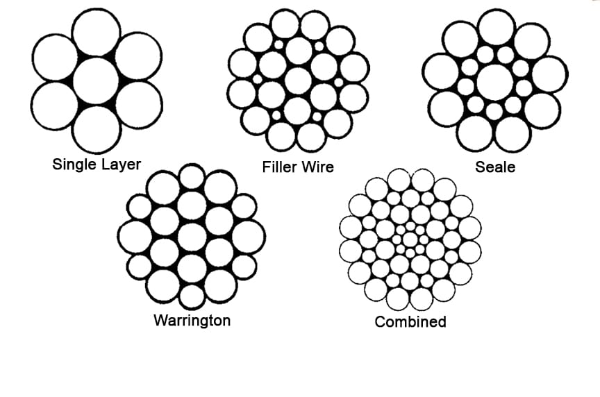
Steel wire ropes are composed of multiple strands of individual wires that surrounding a wire or fiber center to form a combination with excellent fatigue and abrasion resistance. These wires and strands are wound in different directions to from different lay types as follows:
Beside above lay types, alternative lay ropes which combine regular lay and lang lay together and ideal for boom hoist and winch lines, can also be supplied as your request.
Two main methods about seizing steel wire ropes in conjunction with soft or annealing wire or strands to protect cut ends of the ropes form loosening.
Quality Stainless Steel Wire Cable Mesh manufacturers & exporter - buy AISI 316L Ferrule Stainless Steel Wire Cable Mesh | Flexible Wire Rope Mesh from China manufacturer.
Wire rope and cable are each considered a “machine”. The configuration and method of manufacture combined with the proper selection of material when designed for a specific purpose enables a wire rope or cable to transmit forces, motion and energy in some predetermined manner and to some desired end.
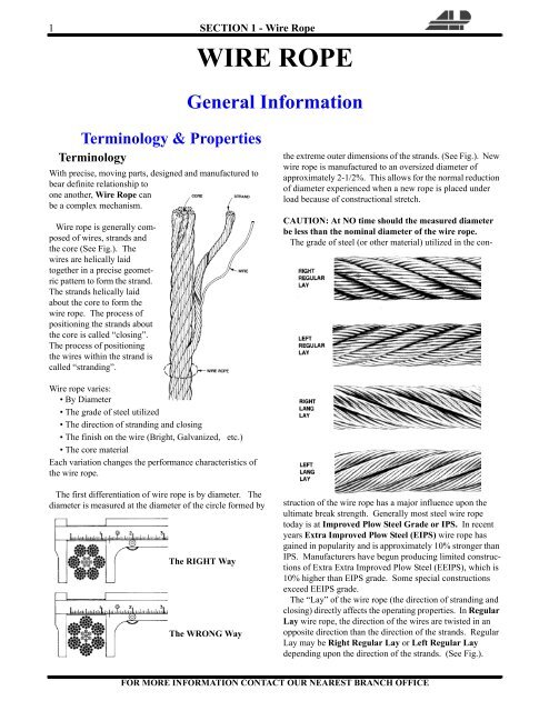
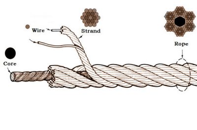
Two or more wires concentrically laid around a center wire is called a strand. It may consist of one or more layers. Typically, the number of wires in a strand is 7, 19 or 37. A group of strands laid around a core would be called a cable or wire rope. In terms of product designation, 7 strands with 19 wires in each strand would be a 7×19 cable: 7 strands with 7 wires in each strand would be a 7×7 cable.
Materials Different applications for wire rope present varying demands for strength, abrasion and corrosion resistance. In order to meet these requirements, wire rope is produced in a number of different materials.
Stainless Steel This is used where corrosion is a prime factor and the cost increase warrants its use. The 18% chromium, 8% nickel alloy known as type 302 is the most common grade accepted due to both corrosion resistance and high strength. Other types frequently used in wire rope are 304, 305, 316 and 321, each having its specific advantage over the other. Type 305 is used where non-magnetic properties are required, however, there is a slight loss of strength.
Galvanized Carbon Steel This is used where strength is a prime factor and corrosion resistance is not great enough to require the use of stainless steel. The lower cost is usually a consideration in the selection of galvanized carbon steel. Wires used in these wire ropes are individually coated with a layer of zinc which offers a good measure of protection from corrosive elements.
Cable Construction The greater the number of wires in a strand or cable of a given diameter, the more flexibility it has. A 1×7 or a 1×19 strand, having 7 and 19 wires respectively, is used principally as a fixed member, as a straight linkage, or where flexing is minimal.
Cables designed with 3×7, 7×7 and 7×19 construction provide for increasing degrees of flexibility but decreased abrasion resistance. These designs would be incorporated where continuous flexing is a requirement.
Selecting Wire Rope When selecting a wire rope to give the best service, there are four requirements which should be given consideration. A proper choice is made by correctly estimating the relative importance of these requirements and selecting a rope which has the qualities best suited to withstand the effects of continued use. The rope should possess:Strength sufficient to take care of the maximum load that may be applied, with a proper safety factor.
Strength Wire rope in service is subjected to several kinds of stresses. The stresses most frequently encountered are direct tension, stress due to acceleration, stress due to sudden or shock loads, stress due to bending, and stress resulting from several forces acting at one time. For the most part, these stresses can be converted into terms of simple tension, and a rope of approximately the correct strength can be chosen. As the strength of a wire rope is determined by its, size, grade and construction, these three factors should be considered.
Safety Factors The safety factor is the ratio of the strength of the rope to the working load. A wire rope with a strength of 10,000 pounds and a total working load of 2,000 pounds would be operating with a safety factor of five.
It is not possible to set safety factors for the various types of wire rope using equipment, as this factor can vary with conditions on individual units of equipment.
The proper safety factor depends not only on the loads applied, but also on the speed of operation, shock load applied, the type of fittings used for securing the rope ends, the acceleration and deceleration, the length of rope, the number, size and location of sheaves and drums, the factors causing abrasion and corrosion and the facilities for inspection.
Fatigue Fatigue failure of the wires in a wire rope is the result of the propagation of small cracks under repeated applications of bending loads. It occurs when ropes operate over comparatively small sheaves or drums. The repeated bending of the individual wires, as the rope bends when passing over the sheaves or drums, and the straightening of the individual wires, as the rope leaves the sheaves or drums, causing fatigue. The effect of fatigue on wires is illustrated by bending a wire repeatedly back and forth until it breaks.
The best means of preventing early fatigue of wire ropes is to use sheaves and drums of adequate size. To increase the resistance to fatigue, a rope of more flexible construction should be used, as increased flexibility is secured through the use of smaller wires.
Abrasive Wear The ability of a wire rope to withstand abrasion is determined by the size, the carbon and manganese content, the heat treatment of the outer wires and the construction of the rope. The larger outer wires of the less flexible constructions are better able to withstand abrasion than the finer outer wires of the more flexible ropes. The higher carbon and manganese content and the heat treatment used in producing wire for the stronger ropes, make the higher grade ropes better able to withstand abrasive wear than the lower grade ropes.
Effects of Bending All wire ropes, except stationary ropes used as guys or supports, are subjected to bending around sheaves or drums. The service obtained from wire ropes is, to a large extent, dependent upon the proper choice and location of the sheaves and drums about which it operates.
A wire rope may be considered a machine in which the individual elements (wires and strands) slide upon each other when the rope is bent. Therefore, as a prerequisite to the satisfactory operation of wire rope over sheaves and drums, the rope must be properly lubricated.
Loss of strength due to bending is caused by the inability of the individual strands and wires to adjust themselves to their changed position when the rope is bent. Tests made by the National Institute of Standards and Technology show that the rope strength decreases in a marked degree as the sheave diameter grows smaller with respect to the diameter of the rope. The loss of strength due to bending wire ropes over the sheaves found in common use will not exceed 6% and will usually be about 4%.
The bending of a wire rope is accompanied by readjustment in the positions of the strands and wires and results in actual bending of the wires. Repetitive flexing of the wires develops bending loads which, even though well within the elastic limit of the wires, set up points of stress concentration.
The fatigue effect of bending appears in the form of small cracks in the wires at these over-stressed foci. These cracks propagate under repeated stress cycles, until the remaining sound metal is inadequate to withstand the bending load. This results in broken wires showing no apparent contraction of cross section.
Experience has established the fact that from the service view-point, a very definite relationship exists between the size of the individual outer wires of a wire rope and the size of the sheave or drum about which it operates. Sheaves and drums smaller than 200 times the diameter of the outer wires will cause permanent set in a heavily loaded rope. Good practice requires the use of sheaves and drums with diameters 800 times the diameter of the outer wires in the rope for heavily loaded fast-moving ropes.
It is impossible to give a definite minimum size of sheave or drum about which a wire rope will operate with satisfactory results, because of the other factors affecting the useful life of the rope. If the loads are light or the speed slow, smaller sheaves and drums can be used without causing early fatigue of the wires than if the loads are heavy or the speed is fast. Reverse bends, where a rope is bent in one direction and then in the opposite direction, cause excessive fatigue and should be avoided whenever possible. When a reverse bend is necessary larger sheaves are required than would be the case if the rope were bent in one direction only.
Stretch of Wire Rope The stretch of a wire rope under load is the result of two components: the structural stretch and the elastic stretch. Structural stretch of wire rope is caused by the lengthening of the rope lay, compression of the core and adjustment of the wires and strands to the load placed upon the wire rope. The elastic stretch is caused by elongation of the wires.
The structural stretch varies with the size of core, the lengths of lays and the construction of the rope. This stretch also varies with the loads imposed and the amount of bending to which the rope is subjected. For estimating this stretch the value of one-half percent, or .005 times the length of the rope under load, gives an approximate figure. If loads are light, one-quarter percent or .0025 times the rope length may be used. With heavy loads, this stretch may approach one percent, or .01 times the rope length.
The elastic stretch of a wire rope is directly proportional to the load and the length of rope under load, and inversely proportional to the metallic area and modulus of elasticity. This applies only to loads that do not exceed the elastic limit of a wire rope. The elastic limit of stainless steel wire rope is approximately 60% of its breaking strength and for galvanized ropes it is approximately 50%.
Preformed Wire Ropes Preformed ropes differ from the standard, or non-preformed ropes, in that the individual wires in the strands and the strands in the rope are preformed, or pre-shaped to their proper shape before they are assembled in the finished rope.
This, in turn, results in preformed wire ropes having the following characteristics:They can be cut without the seizings necessary to retain the rope structure of non-preformed ropes.
They are substantially free from liveliness and twisting tendencies. This makes installation and handling easier, and lessens the likelihood of damage to the rope from kinking or fouling. Preforming permits the more general use of Lang lay and wire core constructions.
Removal of internal stresses increase resistance to fatigue from bending. This results in increased service where ability to withstand bending is the important requirement. It also permits the use of ropes with larger outer wires, when increased wear resistance is desired.
Outer wires will wear thinner before breaking, and broken wire ends will not protrude from the rope to injure worker’s hands, to nick and distort adjacent wires, or to wear sheaves and drums. Because of the fact that broken wire ends do not porcupine, they are not as noticeable as they are in non-preformed ropes. This necessitates the use of greater care when inspecting worn preformed ropes, to determine their true condition.
Tianjin Goldsun Wire Rope Limited (the〝Goldsun〞) is a specialist manufacturer of elevator ropes that is venture between by Hong Kong Publicly Listed Company, Golik Holdings Limited and Tianjin Metallurgy Group Co., Limited, a Top 500 manufacturing enterprise in China. The company pioneered the development and manufacture of wire ropes in China and today distinguishes itself as the market leader in the industry in the manufacture and supply of wire rope products and OEM elevator ropes.
Formed in January 2002, Goldsun perpetuates the beliefs of the importance of quality management, innovation, technical and quality excellence, product leadership, and people development in our pursuit to grow and reach out to more customers. In 2010, Goldsun’s “Three Stage” development strategy guided the investment to build a new RMB150 million state-of-the-art manufacturing facility that is capable of 40,000 tonnes annual output of high-quality and specialized wire ropes. Production began in April 2011 and has enabled the company to deliver better products to our customers at an even higher level of customer experience and satisfaction. Along with an in-house research and development (R&D) unit, the facility at present is equipped with advanced SKET pre-stretch closers, double twist bunchers, sisal core machines, in addition to well over 300 sets of leading domestic surface cleaning, wire drawing, heat treatment, stranding, closing and fatigue testing equipment to place Goldsun as one of the world’s largest integrated single product manufacturer and supplier of its category.
The future and long-term orientation culture ofGoldsun to invest in R&D, technology and in developing the competence of our people in various capacities and across specialist disciplines had allowed us to produce the widest range of elevator ropes in the world that meets customer requirements and complies with OTIS, Japanese and International standards.
In addition to being ISO9001:2000 and Otis Q-Plus certified, Goldsun had also achieved the Korean KTL Production Certification and was first in China to pass fatigue tests conducted at Otis HQ’s Farmington Engineering Test Centre. In 2004,Goldsun supplied the special high speed elevator ropes for the Guinness World Record Zhangjiajie Bailong Elevator which remains in active use today and is highly commended. Furthermore, multiple accolades in product quality excellence was earned numerous times including the National Golden Cup Award, the prestigious designation as the nation’s Top 10 enterprise brand satisfaction survey in 2006, and for five consecutive times over a period of fifteen year, laurels in product and after-sale service excellence by the China Quality Association Users Committee and National Construction Machinery Equipment Users Committee.
At the heart of Goldsun’s world-class capabilities in R&D, design and manufacture are bespoke services and solutions for our customers starting from application selection through to installation and maintenance. Our wide selection of products and our network of service centers in Guangzhou, Shanghai, Chongqing, Suzhou and Chengdu give us the ability to offer customers timely services in cut-to-length orders, packaging and distribution; and make Goldsun the top supplier of elevator ropes in China for many years running. Goldsun is also the qualified supplier for companies like OTIS, Hitachi, Toshiba, Yongtay, Tissen, and etcetera.

Rope diameter is specified by the user and is generally given in the equipment manufacturer’s instruction manual accompanying the machine on which the rope is to be used.
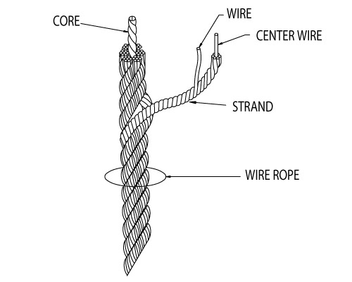
Rope diameters are determined by measuring the circle that just touches the extreme outer limits of the strands— that is, the greatest dimension that can be measured with a pair of parallel-jawed calipers or machinist’s caliper square. A mistake could be made by measuring the smaller dimension.
The right way to unreel.To unreel wire rope from a heavy reel, place a shaft through the center and jack up the reel far enough to clear the floor and revolve easily. One person holds the end of the rope and walks a straight line away from the reel, taking the wire rope off the top of the reel. A second person regulates the speed of the turning reel by holding a wood block against the flange as a brake, taking care to keep slack from developing on the reel, as this can easily cause a kink in the rope. Lightweight reels can be properly unreeled using a vertical shaft; the same care should be taken to keep the rope taut.
The wrong way to unreel.If a reel of wire rope is laid on its flange with its axis vertical to the floor and the rope unreeled by throwing off the turns, spirals will occur and kinks are likely to form in the rope. Wire rope always should be handled in a way that neither twists nor unlays it. If handled in a careless manner, reverse bends and kinks can easily occur.
The right way to uncoil.There is only one correct way to uncoil wire rope. One person must hold the end of the rope while a second person rolls the coil along the floor, backing away. The rope is allowed to uncoil naturally with the lay, without spiraling or twisting. Always uncoil wire rope as shown.
The wrong way to uncoil.If a coil of wire rope is laid flat on the floor and uncoiled by pulling it straight off, spirals will occur and kinking is likely. Torsions are put into the rope by every loop that is pulled off, and the rope becomes twisted and unmanageable. Also, wire rope cannot be uncoiled like hemp rope. Pulling one end through the middle of the coil will only result in kinking.
Great stress has been placed on the care that should be taken to avoid kinks in wire rope. Kinks are places where the rope has been unintentionally bent to a permanent set. This happens where loops are pulled through by tension on the rope until the diameter of the loop is only a few inches. They also are caused by bending a rope around a sheave having too severe a radius. Wires in the strands at the kink are permanently damagedand will not give normal service, even after apparent “re-straightening.”
When wire rope is wound onto a sheave or drum, it should bend in the manner in which it was originally wound. This will avoid causing a reverse bend in the rope. Always wind wire rope from the top of the one reel onto the top of the other.Also acceptable, but less so, is re-reeling from the bottom of one reel to the bottom of another. Re-reeling also may be done with reels having their shafts vertical, but extreme care must be taken to ensure that the rope always remains taut. It should never be allowed to drop below the lower flange of the reel. A reel resting on the floor with its axis horizontal may also be rolled along the floor to unreel the rope.
Wire rope should be attached at the correct location on a flat or smooth-faced drum, so that the rope will spool evenly, with the turns lying snugly against each other in even layers. If wire rope is wound on a smooth-face drum in the wrong direction, the turns in the first layer of rope will tend to spread apart on the drum. This results in the second layer of rope wedging between the open coils, crushing and flattening the rope as successive layers are spooled.
A simple method of determining how a wire rope should be started on a drum. The observer stands behind the drum, with the rope coming towards him. Using the right hand for right-lay wire rope, and the left hand for left lay wire rope, the clenched fist denotes the drum, the extended index finger the oncoming rope.
Clips are usually spaced about six wire rope diameters apart to give adequate holding power. They should be tightened before the rope is placed under tension. After the load is placed on the rope, tighten the clips again to take care of any lessening in rope diameter caused by tension of the load. A wire rope thimble should be used in the eye of the loop to prevent kinking.
U-bolt Clips.There is only one correct method for attaching U-bolt clips to wire rope ends, as shown in TheRightWayimage below. The base of the clip bears on the live end of the rope; the “U” of the bolt bears on the dead end.
Compare this with the incorrect methods. Five of the six clips shown are incorrectly attached—only the center clip in the top view is correct. When the “U” of the clip bears on the live end of the rope, there is a possibility of the rope being cut or kinked, with subsequent failure.
Proper seizing and cutting operations are not difficult to perform, and they ensure that the wire rope will meet the user’s performance expectations. Proper seizings must be applied on both sides of the place where the cut is to be made. In a wire rope, carelessly or inadequately seized ends may become distorted and flattened, and the strands may loosen. Subsequently, when the rope is operated, there may be an uneven distribution of loads to the strands; a condition that will significantly shorten the life of the rope.
Either of the following seizing methods is acceptable. Method No. 1 is usually used on wire ropes over one inch in diameter. Method No. 2 applies to ropes one inch and under.
Method No. 1: Place one end of the seizing wire in the valley between two strands. Then turn its long end at right angles to the rope and closely and tightly wind the wire back over itself and the rope until the proper length of seizing has been applied. Twist the two ends of the wire together, and by alternately pulling and twisting, draw the seizing tight.
The Seizing Wire. The seizing wire should be soft or annealed wire or strand. Seizing wire diameter and the length of the seize will depend on the diameter of the wire rope. The length of the seizing should never be less than the diameter of the rope being seized.
Proper end seizing while cutting and installing, particularly on rotation-resistant ropes, is critical. Failure to adhere to simple precautionary measures may cause core slippage and loose strands, resulting in serious rope damage. Refer to the table below ("Suggested Seizing Wire Diameters") for established guidelines. If core protrusion occurs beyond the outer strands, or core retraction within the outer strands, cut the rope flush to allow for proper seizing of both the core and outer strands.
The majority of wire rope problems occurring during operation actually begin during installation, when the rope is at its greatest risk of being damaged. Proper installation procedures are vital in the protection and performance of wire rope products.
Until the rope is installed it should be stored on a rack, pallet or reel stand in a dry, well-ventilated storage shed or building. Tightly sealed and unheated structures should be avoided as condensation between rope strands may occur and cause corrosion problems. If site conditions demand outside storage, cover the rope with waterproof material and place the reel or coil on a support platform to keep it from coming directly in contact with the ground.
While lubrication is applied during the manufacturing process, the wire rope must still be protected by additional lubrication once it is installed. Lubricants will dry out over a period of time and corrosion from the elements will occur unless measures are taken to prevent this from happening. When the machine becomes idle for a period of time, apply a protective coating of lubricant to the wire rope. Moisture (dew, rain, and snow) trapped between strands and wires will create corrosion if the rope is unprotected. Also apply lubricant to each layer of wire rope on a drum because moisture trapped between layers will increase the likelihood of corrosion.
Always use the nominal diameter as specified by the equipment manufacturer. Using a smaller diameter rope will cause increased stresses on the rope and the probability of a critical failure is increased if the rated breaking strength does not match that of the specified diameter. Using a larger diameter rope leads to shorter service life as the rope is pinched in the sheave and drum grooves which were originally designed for a smaller diameter rope. Just as using a different diameter rope can create performance problems, so can the use of an excessively undersized or oversized rope.
Measure the wire rope using a parallel-jawed caliper as discussed in Measuring Rope Diameter at the top of this page. If the rope is the wrong size or outside the recommended tolerance, return the rope to the wire rope supplier. It is never recommended nor permitted by federal standards to operate cranes with the incorrect rope diameter. Doing so will affect the safety factor or reduce service life and damage the sheaves and drum. Note that in a grooved drum application, the pitch of the groove may be designed for the rope’s nominal diameter and not the actual diameter as permitted by federal standards.
Wire rope can be permanently damaged by improper unreeling or uncoiling practices. The majority of wire rope performance problems start here.Improper unreeling practices lead to premature rope replacement, hoisting problems and rope failure.
Place the payout reel as far away from the boom tip as is practical, moving away from the crane chassis. Never place the payout reel closer to the crane chassis than the boom point sheave. Doing so may introduce a reverse bend into the rope and cause spooling problems. Follow the guidelines highlighted under Unreeling and Uncoiling and Drum Winding. Take care to determine whether the wire rope will wind over or under the drum before proceeding. If the wire rope supplier secured the end of the rope to the reel by driving a nail through the strands, ask that in the future a U-bolt or other nondestructive tie-down method be used; nails used in this manner damage the rope.
Take extra precaution when installing lang lay, rotation-resistant, flattened strand or compacted ropes. Loss of twist must be avoided to prevent the strands from becoming loosened, causing looped wire problems.
The end of the rope must be securely and evenly attached to the drum anchorage point by the method recommended by the equipment manufacturer. Depending on the crane’s regulatory requirements, at least two to three wraps must remain on the drum as dead wraps when the rope is unwound during normal operations. Locate the dead end rope anchorage point on the drum in relation to the direction of the lay of the rope. Do not use an anchorage point that does not correspond with the rope lay. Mismatching rope lay and anchorage point will cause the wraps to spread apart from each other and allow the rope to cross over on the drum. Very gappy winding will occur resulting in crushing damage in multilayer applications.
Back tension must be continually applied to the payout reel and the crewman installing the rope must proceed at a slow and steady pace whether the drum is smooth or grooved.Regardless of the benefits of a grooved drum, tension must be applied to ensure proper spooling. An improperly installed rope on a grooved drum will wear just as quickly as an improperly installed rope on a smooth drum. If a wire rope is poorly wound and as a result jumps the grooves, it will be crushed and cut under operating load conditions where it crosses the grooves.
Every wrap on the first or foundation layer must be installed very tightly and be without gaps. Careless winding results in poor spooling and will eventually lead to short service life. The following layers of rope must lay in the grooves formed between adjacent turns of the preceding layer of rope. If any type of overwind or cross-winding occurs at this stage of installation and is not corrected immediately, poor spooling and crushing damage will occur.
On a multilayer spooling drum be sure that the last layer remains at least two rope diameters below the drum flange top. Do not use a longer length than is required because the excess wire rope will cause unnecessary crushing and may jump the flange. Loose wraps that occur at any time must be corrected immediately to prevent catastrophic rope failure.
The use of a mallet is acceptable to ensure tight wraps, however a steel-faced mallet should be covered with plastic or rubber to prevent damage to the rope wires and strands.
Rotation-resistant ropes of all constructions require extra care in handling to prevent rope damage during installation. The lay length of a rotation-resistant rope must not be disturbed during the various stages of installation. By introducing twist or torque into the rope, core slippage may occur—the outer strands become shorter in length, the core slips and protrudes from the rope. In this condition the outer strands become over- loaded because the core is no longer taking its designed share of the load. Conversely, when torque is removed from a rotation-resistant rope core slippage can also occur. The outer strands become longer and the inner layers or core become overloaded, reducing service life and causing rope failure.
The plain end of a wire rope must be properly secured. If the entire cross section of the rope is not firmly secured, core slippage may occur, causing the core to pull inside the rope’s end and allowing it to protrude elsewhere, either through the outer strands (popped core) or out the other end of the line. The outer layer of the outside strands may also become overloaded as there is no complete core-to-strand support.
Secure the ends of the rope with either seizing or welding methods as recommended under Seizing Wire Rope. It is imperative that the ends be held together tightly and uniformly throughout the entire installation procedure, including attaching the end through the wedge socket and the drum dead end wedge
When installing a new line, connect the old line to the new line by using a swivel-equipped cable snake or Chinese finger securely attached to the rope ends. The connection between the ropes during change-out must be very strong and prevent torque from the old rope being transferred into the new rope.Welding ropes together or using a cable snake without the benefit of a swivel increases the likelihood of introducing torque into the new rope. A swivel-equipped cable snake is not as easy as welding the ropes, but this procedure can be mastered with a little patience and practice.

Wire ropes can be seen everywhere around us, they are made of strands or bundles of individual wires constructed around an independent core, suitable for construction, industrial, fitness, commercial, architectural, agricultural, and marine rigging applications.
Wire rod is made from high carbon steel wires(0.35 to 0.85 percent carbon) in a hot rolling process of a required diameter, usually from 5.5mm to 8 mm.
Wire rod is drawn to the required diameter by the 1st drawing machine after descaling dust and rust, adding mechanical properties suitable for application.
Positioning the wires different or the same size lay in multiple layers and same direction, or cross lay and diameter is maintained by one-third of the rope size.
So in theory, it is very simple to manufacture wire ropes. However there are many more details that must be closely monitored and controlled, and this requires time and experienced personnel since it is a super complicated project you cannot imagine.

Sheaves facilitate the smooth and safe operation of overhead crane hoists. Damaged sheaves can wear ropes prematurely and cause other dangerous hazards, such as binding wire rope. Konecranes technicians are trained to identify and correct problems with sheaves and other parts of hoisting equipment.
Sheaves carrying ropes which can be momentarily unloaded shall be provided with close-fitting guards or other suitable devices to guide the rope back into the groove when the load is applied again.
The sheaves in the bottom block shall be equipped with close-fitting guards that will prevent ropes from becoming fouled when the block is lying on the ground with ropes loose.
In using hoisting ropes, the crane manufacturer"s recommendation shall be followed. The rated load divided by the number of parts of rope shall not exceed 20 percent of the nominal breaking strength of the rope.
Rope clips attached with U-bolts shall have the U-bolts on the dead or short end of the rope. Spacing and number of all types of clips shall be in accordance with the clip manufacturer"s recommendation. Clips shall be drop-forged steel in all sizes manufactured commercially. When a newly installed rope has been in operation for an hour, all nuts on the clip bolts shall be retightened.
Wherever exposed to temperatures, at which fiber cores would be damaged, rope having an independent wirerope or wire-strand core, or other temperature-damage resistant core shall be used.
Replacement rope shall be the same size, grade, and construction as the original rope furnished by the crane manufacturer, unless otherwise recommended by a wire rope manufacturer due to actual working condition requirements.
Konecranes wire rope inspections can help crane users extend the life of hoist ropes. Ropes, sheaves and other reeving system components are inspected for compliance with crane standards, and to determine if they have flaws that could hinder safe operation. Contact us today to schedule an assessment.

Wire rope is widely used in mining operations due to its high strength, light weight, and good elasticity [1,2]. However, the degree of damage sustained by the wire rope increases considerably with the increase in the usage time and due to the increase in the long-term impact of factors such as tensile bending, alternating loads, and the environment. Furthermore, this damage is inevitable if it is not addressed in time, and it can adversely affect the productivity of mining operations and threaten the safety of both the personnel and the equipment. Coal mine safety regulations have been established to ensure the productivity of mining operations; according to these regulations, mining hoist ropes must be tested every day and their scrap period is two years. If the degree of damage does not exceed the relevant provisions, their usage can be extended by no more than one year.
Various methods have been proposed for the non-destructive testing of wire ropes. Most of the current studies are focused on methods such as ultrasonic detection [3], electromagnetic detection [4], X-ray detection, and magnetostriction [5], as well as eddy current, current, and vibration detection [6,7]. The electromagnetic detection method is the most widely implemented method, owing to its demonstrated reliability and practicality. The basic principle of the electromagnetic-based leakage detection method used in this study is shown in Figure 1. The permanent magnet magnetizes the wire rope to saturation, forming a closed magnetic circuit among the wire rope, magnet, and yoke. In the presence of a damage, the original magnetic induction lines through the wire rope form a closed magnetic circuit in the air and generate a leakage magnetic field.
When using the electromagnetic detection method to detect leakage, the wire rope detection signal is mixed with a variety of sources of interference noise, including the spiral structure of the wire rope, which produces periodic changes in the strand noise; the detection of the magnetic field in an environment of complex and variable high-frequency low-amplitude noise; the shaking of the wire rope during the operation process, producing low -frequency random noise; electromagnetic interference issuing from the electromagnetic detection circuit; detection line voltage jitter; drift; and other sources of noise, all of which affect the accurate judgment of the leakage signal. To address the aforementioned challenges, Peng, F. et al. [8] applied a multi-stage filtering method based on EEMD and optimal wavelets in three-dimensional UME signal processing to effectively suppress noise interference. Zhang, J. et al. [9] proposed a new filtering system consisting of the Hilbert yellow transform and compressive-aware wavelet filtering to denoise strand and high-frequency noises. Furthermore, Chun et al. [10] designed a filter based on the multi-stage wavelet analysis of a time-domain-reflection method. Moreover, they effectively eliminated the wild-point noise and industrial frequency interference noise. The abovementioned wire rope damage signal has been studied extensively. However, because the effect of wavelet packet decomposition depends on the choice of the wavelet basis function and the number of decomposition layers, it is not an adaptive signal decomposition method. In recent years, EMD has been widely used in mechanical fault diagnosis. However, owing to the existence of endpoint effects and modal confusion, this algorithm needs to be further studied. To address the limitations of EMD and WT, Dragomiretskiy et al. [11] proposed a new adaptive time-frequency analysis method called VMD in 2014. Compared with EMD and AWT, VMD can suppress interference signals, prevent the loss of useful information, and provide a high-quality data source for subsequent feature extraction. Moreover, it has high decomposition accuracy and operational efficiency and can effectively suppress the overlap mode in a signal decomposition process.
Wire rope detection is challenging because of signal noise reduction, as well as the difficulties involved in achieving a quantitative detection process following noise reduction, owing to the complex structure, shape, and location of the wire rope, which itself produces different types of defects. To solve this problem, some scholars have conducted representative studies. Li, J. et al. designed a nondestructive wire rope inspection device which used double detection plates to collect MFL data, improved the image resolution based on a super-resolution algorithm, and finally used the AdaBoost classifier to classify the defect images [12]. Zhang, J. designed a device based on a residual magnetic field device, proposing a novel filtering system to improve the signal-to-noise ratio, and at the same time used digital image processing techniques to achieve the quantitative recognition of defect images [13,14]. Tan, X. proposed a novel test structure with a huge array of magnetoresistive sensors to effectively identify multiple types of damage and finally applied radial basis neural networks for the quantitative recognition of magnetic images [15]. W Sharatchandra Singh et al. designed an ultrasonic sensor to detect wire rope damage signals by means of ultrasonic detection method and conducted quantitative recognition research using a BP neural network [16]. Artificial neural networks and related algorithms have contributed significantly to the field of pattern recognition. However, their recognition performance is significantly influenced by several parameters and can easily fall into a local minima in the optimization process. However, SVMs have few adjustable parameters and stable operation [17]. Thus, with fewer training samples, higher diagnostic accuracy can be achieved. Therefore, in this study we used SVMs based on PSO for the identification of internal and external wire rope damages.
In summary, it is difficult to detect the internal damage of wire ropes using the existing flaw detection equipment. Therefore, we have designed a wire rope detection device based on leakage magnetism. The detection device is implemented using permanent magnets to magnetize the wire rope, axial, and radial magnetization sensors in order to obtain the wire rope defect information. At the same time, the mapping relationship between internal damage and external damage was analyzed using the finite element method to prepare for the experiment. The VMD-AWT noise reduction method is used to reduce the noise of the original signal and calculate the wavelet information entropy based on the reconstructed signal to construct a multidimensional feature vector. Finally, the PSO-SVM algorithm is proposed to effectively and quantitatively classify and identify the internal and external defects of the wire rope using a multi-dimensional feature vector dataset.


 8613371530291